 Tweet
Tweet
Battery Testing...Today.
Hello everyone,
I am actually running some tests with Batteries as the Power Supply...Batteries are 12V 33 A/H AGM, Deep-cycle.
[IMG]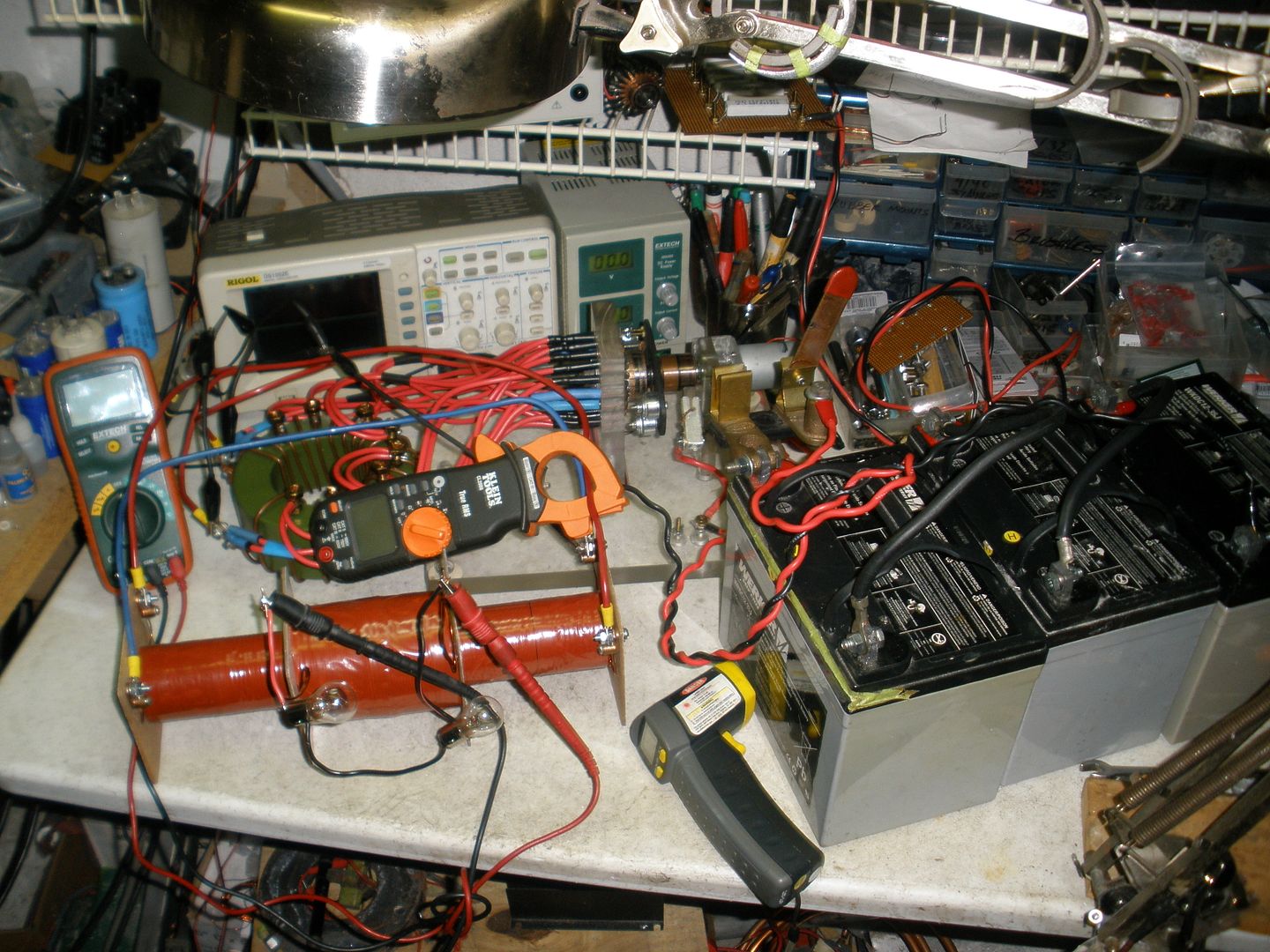 [/IMG]
And here I am just verifying what I wrote previously to Cornboy...
Batteries, once connected to this System...will disburse ALL their FULL Power into it...without absolutely No Regulation on Volts or Amps...but only based on the Inductance Regulation from our Part G...Since We are Operating at such Low Levels of Resistance.
My Part G is still wound with 8 awg, and 20 turns...same way as I had before.
I started with 3 Batteries fully charged to 39.0 V...and they Disbursed 54 Amps...I have a Blade Switch on...and Primaries climbed to 272� F...had to cut off power in less than one minute of running time...Not Good Results.
My next test was with 24 Volts (Two Batteries)...it disbursed -roughly- 30Amps...not good either.
Reduced it just one Battery...and it spent 19 Amps...not good results.
And when I write "not good results" I meant relating to very poor induction at Secondaries...and not just relating to heat and higher amperage.
And the problem bolts down to the way the Dual Signals become (I rather should write "Deform" here) at any of these levels of power...
[IMG]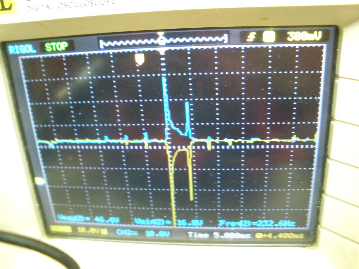 [/IMG]
Above is the Signal for 24V (Two Batteries)
[IMG]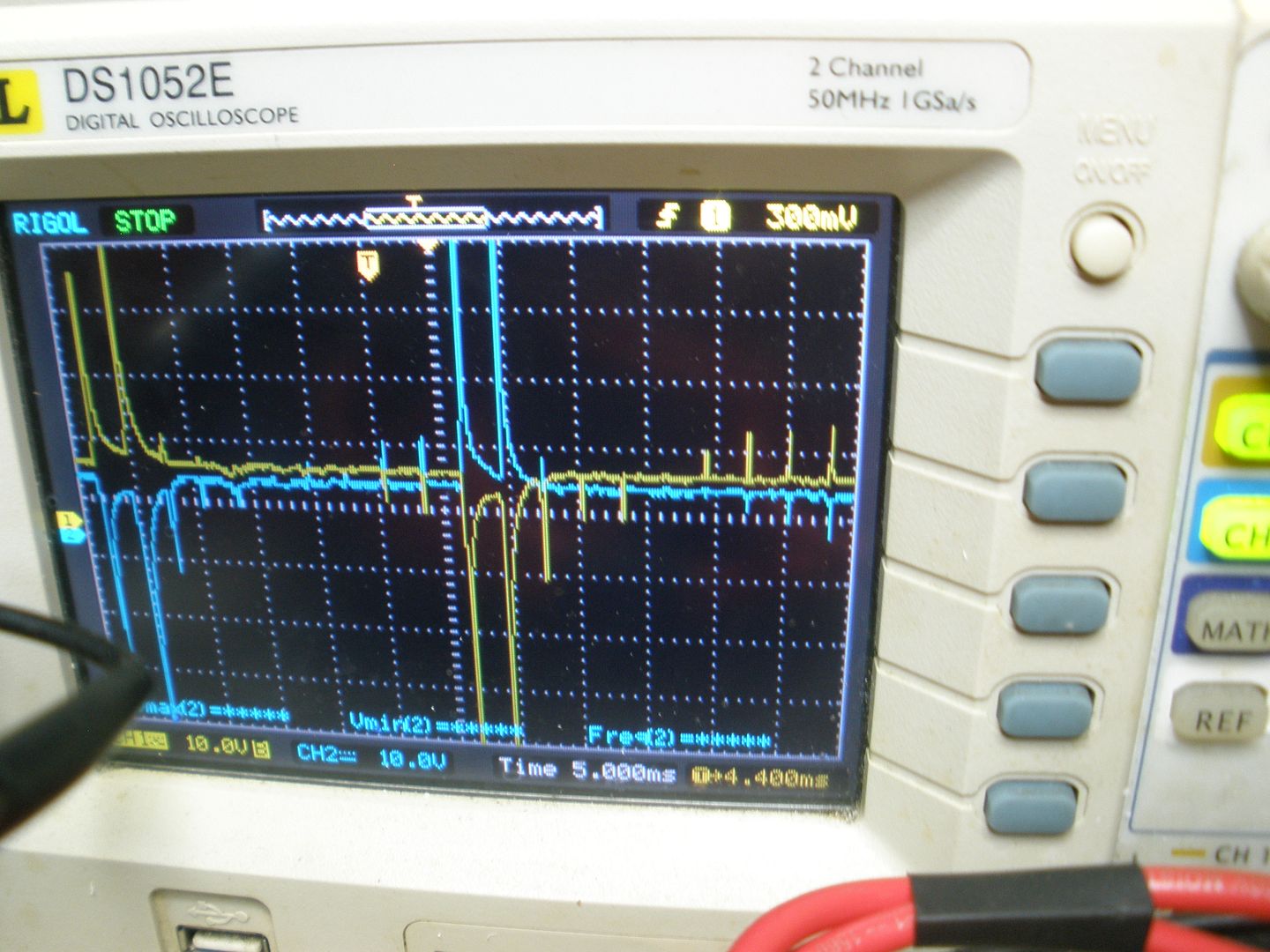 [/IMG]
And above is the Signal for 12V
Note the Rise and Drop off are simultaneously taking place around zero Time.
Collapsing Field Alternatively below Zero Values...NOT GOOD!!
Big difference when I did the Test with 36V 2+ Amp Max out with Lipo Batteries...except they started to burst and dripping liquid...overheated...But Induction was great as Signal was right.
However, even being not such good tests...I enter into a new reasoning (which I will be testing as well) about this whole system.
I will share them below for any comments or suggestions...
Part G Regulates Currents based on Inductance -at the same, exact time toward - Primary(es) N and Primary(es) S Coils.
I would say that INDUCTANCE Calculation from our Part G Coil, MUST BE in completely DIRECT FUNCTION RELATION to our Primaries N and (or) S Coils INDUCTANCE .
I think based on the above we could Establish this Inductance Relations in either Two Ways...
1- Part G Inductance (Lg) should be -at least- the SUM of Our N and S Primaries Inductance (Lg=Ln+Ls)
2- Part G Inductance (Lg) should be -at least- EQUAL to JUST ONE of Our Primaries N and S Inductance (Lg=Ln=Ls)
And just because Part G Inductance Disburses Currents within exactly the SAME TIME to BOTH N and S Coils...I will rather choose number 2 above.
Which resumes that Part G should be NO MORE and NO LESS than the Inductance from one of our Primary Coils Calculation.
This way our System would be able to be tested with different current inputs...
If We choose number 1 option: (Lg=Ls+Ln), then Part G would be operating based on DOUBLE THE INDUCTANCE VALUE to Both Primaries SINGLE INDUCTANCE VALUE within SAME TIME....And I do not see this mode of operation right at all.
I believe if we get here...we will be able to come up with the right Calculations to be adapted to any of our systems, no matter the differences.
Anyways...this is my take on this system....And any opinions welcome.
Regards
Ufopolitics
Hello everyone,
I am actually running some tests with Batteries as the Power Supply...Batteries are 12V 33 A/H AGM, Deep-cycle.
[IMG]
 [/IMG]
And here I am just verifying what I wrote previously to Cornboy...
Batteries, once connected to this System...will disburse ALL their FULL Power into it...without absolutely No Regulation on Volts or Amps...but only based on the Inductance Regulation from our Part G...Since We are Operating at such Low Levels of Resistance.
My Part G is still wound with 8 awg, and 20 turns...same way as I had before.
I started with 3 Batteries fully charged to 39.0 V...and they Disbursed 54 Amps...I have a Blade Switch on...and Primaries climbed to 272� F...had to cut off power in less than one minute of running time...Not Good Results.
My next test was with 24 Volts (Two Batteries)...it disbursed -roughly- 30Amps...not good either.
Reduced it just one Battery...and it spent 19 Amps...not good results.
And when I write "not good results" I meant relating to very poor induction at Secondaries...and not just relating to heat and higher amperage.
And the problem bolts down to the way the Dual Signals become (I rather should write "Deform" here) at any of these levels of power...
[IMG]
 [/IMG]
Above is the Signal for 24V (Two Batteries)
[IMG]
 [/IMG]
And above is the Signal for 12V
Note the Rise and Drop off are simultaneously taking place around zero Time.
Collapsing Field Alternatively below Zero Values...NOT GOOD!!
Big difference when I did the Test with 36V 2+ Amp Max out with Lipo Batteries...except they started to burst and dripping liquid...overheated...But Induction was great as Signal was right.
However, even being not such good tests...I enter into a new reasoning (which I will be testing as well) about this whole system.
I will share them below for any comments or suggestions...
Part G Regulates Currents based on Inductance -at the same, exact time toward - Primary(es) N and Primary(es) S Coils.
I would say that INDUCTANCE Calculation from our Part G Coil, MUST BE in completely DIRECT FUNCTION RELATION to our Primaries N and (or) S Coils INDUCTANCE .
I think based on the above we could Establish this Inductance Relations in either Two Ways...
1- Part G Inductance (Lg) should be -at least- the SUM of Our N and S Primaries Inductance (Lg=Ln+Ls)
2- Part G Inductance (Lg) should be -at least- EQUAL to JUST ONE of Our Primaries N and S Inductance (Lg=Ln=Ls)
And just because Part G Inductance Disburses Currents within exactly the SAME TIME to BOTH N and S Coils...I will rather choose number 2 above.
Which resumes that Part G should be NO MORE and NO LESS than the Inductance from one of our Primary Coils Calculation.
This way our System would be able to be tested with different current inputs...
If We choose number 1 option: (Lg=Ls+Ln), then Part G would be operating based on DOUBLE THE INDUCTANCE VALUE to Both Primaries SINGLE INDUCTANCE VALUE within SAME TIME....And I do not see this mode of operation right at all.
I believe if we get here...we will be able to come up with the right Calculations to be adapted to any of our systems, no matter the differences.
Anyways...this is my take on this system....And any opinions welcome.
Regards
Ufopolitics


 as NO other tool i have found has this aspect that is so very importantly related.
Comment