Announcement

Collapse
No announcement yet.

Ron Brandt's Perm-Mag, the QEG, the MEG and "magnetic flux switching" explained

Collapse
X
 
  • Filter
  • Time
  • Show
Clear All
new posts

  • Ron Brandt's Perm-Mag, the QEG, the MEG and "magnetic flux switching" explained

    In the thread about the Witts generator, I posted quite some information about the device which has been demonstrated by Witts, which is nothing other than the experimental "Ecklin Variable Releluctance Generator" built by none other than Ronald Brandt. The same Ron Brandt, which gave John Bedini the plans for what is now called the "Tesla Switch":

    http://www.energeticforum.com/renewa...tml#post297009

    From an article about Ron Brandt's devices from 1994, it becomes clear that the plans the QEG project is based on, are not the actual plans for Ron's device, but those of the Ecklin's device, about which Ron said something was missing, which he added in order to make it work. After that, he designed his Perm-Mag motor in order to come to further improvements, of which obviously the most important ingredient would be the addition of a permanent magnet to the rotor. In other words, the quest by the QEG team for finding "resonance" is a fruitless endeavor, because the secret is in the magnetic flux switching principle and not in the optimization thereof.

    Now that the plans of his Perm-Mag motor have been released, we can reconstruct the story, understand the principle he utilized, magnetic flux switching (as in the MEG), and come to proposals how to make the QEG actually working.

    Let me post a summary of the info here and create a new thread for this discussing this.

    ----

    Do you know what this thing actually is and who built it??

    It's Ron Brandt's "Ecklin Variable Reluctance Generator". See page 14 in this pdf, with a photograph of (the main frame of) the exact same device:

    http://www.tuks.nl/pdf/Reference_Mat...sue-4-1994.pdf

    Recently, they released these video's, which contain a presentation by Ron Brandt with his motor:
    https://www.youtube.com/channel/UCf0...4m-byUpNTRZcTg

    You can find more about this Ecklin device here:
    John W Ecklin -- Stationary armature generator -- US Patent 3879633, US Patent 4567407, 12 articles

    Ron's Ecklin device seems to have been his first prototype, which eventually led to his PermMag motor, of which they've made the plans available on Google drive just months ago:
    FREE Ron Brandt Plans

    From what I make of it, this is essentially "magnetic flux switching" technology, the same principle as has been patented as the "MEG" by a/o Tom Bearden. His colleagues posted a very interesting video, explaining how they got to the MEG design and how "flux switching" works:
    https://youtu.be/no50_5iSr2Y

    Originally posted by QEG View Post
    Yes the FTW QEG looks exactly like the WITTS Generator because James Robitaille of FTW was trained by Timothy Thrapp of WITTS.
    Ok, that explains quite a lot.

    So, this is the story as far as I am able to reconstruct:

    *) During the 70's, Ron Brandt built an electric car, powered by a circuit now called the "Tesla Switch", a scaled down version of which was demonstrated in 1984 by John Bedini.

    *) In the 1980s, Ron started working on magnetic motors based on "flux switching", based on Ecklin's theory. His "Ecklin Variable Reluctance Generator" was the first experimental device he build, with which he could achieve a COP of 1.05 (105%), which was unsatisfactory to him.

    *) Ron designed a new type of motor, his Perm-Mag motor, whereby he placed magnets at the inside of a rotating cylinder, rotating around the stator. Because the magnets are supported by the cylinder, they can't "fly away" at high RPMs. He built (at least) two prototypes, of which he demonstrated the smaller one at the "Extraordinary Science Conference" in 1995. A video of his presentation has recently been made available by witts.

    *) Ron kept on experimenting with these two Perm-Mag motors, rewinding them every now and then.

    *) In January, 2010, Witts posts a video with a demonstration of Ron's variable reluctance prototype:
    https://www.youtube.com/watch?v=LFu-s6ZmGyE

    *) After Ron passed away in 2010, Witts got hold of at least his variable reluctance prototype and possibly also the Perm-Mag motors. Apparently the only prototype still in a working condition was the variable reluctance prototype, which - according to Ron - could only do a COP of about 1.05.

    In the paper referenced earlier, there's another interesting photo at page 15:
    It's caption reads:

    Ron Brandt holding a six-pole rotor of an Ecklin variable reluctance motor-generator. There's a two-pole rotor in the box.
    That's rather interesting, because the Ecklin patent shows a two-pole rotor and it is pretty clear Ron's device incorporates four stator poles. That already hints in the direction of utilizing magnetic flux switching, as is also being done in the MEG. Further, in the plans for Ron's Perm-Mag motor released by Witts, there is a directory about Joseph Newmann's motor and a directory about "their" "flux switching transformer", which IS the MEG and also refers to Naudin's Meg page:

    Replications & Additional Technical Data:
    The MEG - "Motionless Electromagnetic Generator" from Tom Bearden
    I highly recommend watching this video by Lee Kenny, one of the inventors of the MEG, which shows you exactly how magnetic flux switching works and how they got to the current design of the MEG:

    https://youtu.be/no50_5iSr2Y

    Now take a look at what you can see from the actual rotor in the demonstration video by Witts:

    https://youtu.be/LFu-s6ZmGyE?t=2m50s

    Does this look anything like the rotor they are using in the QEG?

    No, it looks like a disc on which something is mounted with a screw...

    Now remember, this is Ron's experimental prototype, and in his presentation he says the Ecklin device was only theory and that he added something with which he has been able to make it work. And also remember that the knowledge he gained from experimenting with this device allowed him to design his Perm-Mag motor.

    So, it seems clear that a permanent magnet needs to be part of the rotor in order to get a COP>1, which would suggest a rotor as in the Zimmerman patent as posted by vidbid:

    https://www.google.com/patents/US2816240
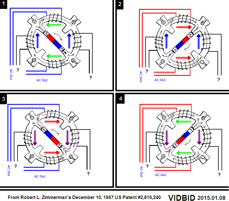

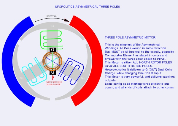
    However, with a rotor shaped like this, there is no way you can smoothly switch the magnetic flux of the permanent magnet from one set of poles to the next, so you would need a rotor specifically designed for flux switching, which brings me to some pictures posted by UfoPolitics in his thread a while ago:

    http://www.energeticforum.com/renewa...-machines.html

    http://www.tuks.nl/img/UfoPolitics_Free_Energy/img/


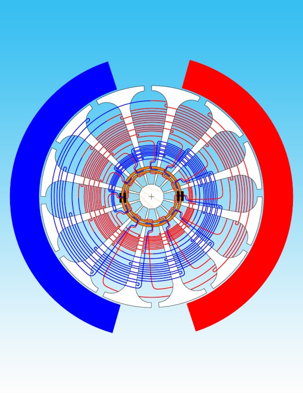
    Now let's compare this to Ron's stator design, which is supposed to have 49 gaps (so 50 "pins"). Like Ron, I didn't count them in this image, but there should be 49 gaps:
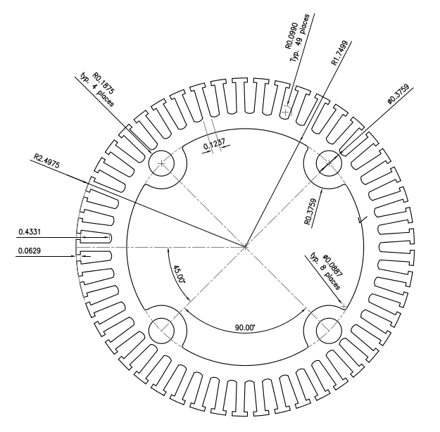

    And this is how this looks like in the big prototype of his Perm-Mag motor:
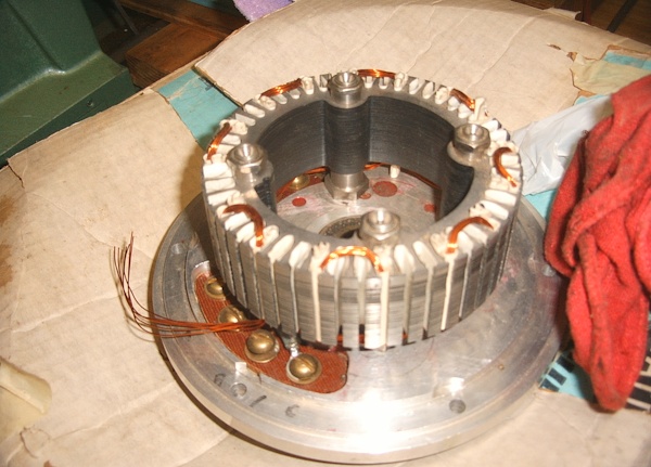

    High res: http://www.tuks.nl/img/Brandt_Stator_photo.jpg

    If I counted correctly, in Ron's Perm-Mag motor there's three stator pins for every magnet, allowing the magnetic flux from every rotating magnet to find a path trough multiple pins and smoothly switch from one pin to the next. All one needs to do is to direct the magnetic flux trough a pin you'd like it to go trough, as explained by Bearden's colleages in their video. All it takes to do that, it to pulse a coil around the pin you'd like the flux to go trough next.

    An important difference between Ron's design and UfoPolitics is that with Ron's motor, the magnets are rotating and no brushes are required, while with UfoPolitics version, it's the other way around.

    The photograph suggests Ron, like UfoPolitics, wound his coils around three stator pins at a time (covering one magnet), but he re-wound his motors multiple times, so it's definitely not certain this way of winding is best.

    What this means for getting the QEG working.

    The challenge to get the QEG working is not to find some kind of "resonance". Yes, there are optimal frequencies to work with and probably you need to work around those frequencies in order to get a COP >> 1, but that's not the essential point.

    What is essential with these kinds of motor/generators is the way the flux is being switched/directed from one set of poles to the next. From the video revealing the actual rotor and the fact Ron also had a 6-pole rotor for the device, it is clear that Ron experimented with the rotor and that the addition of a permanent magnet is what made the difference.

    What he found out is that he could not run his first "Ecklin" device at high RPMs, because of centripetal forces acting on the magnets in the rotor, which is why he designed a rotor consisting of a cylinder, which prevents the magnets from being ripped of the rotor at high RPMs. Also, the magnets on his Perm-Mag rotor were slightly bent, so there is very little space between the rotor and the stator (magnets) during operation.

    So, in order to get the QEG working with a COP>1, one needs to design a rotor for this device, which incorporates at least one permanent magnet, in such a way that the magnetic flux can be directed from one set of poles to the next smoothly.

    The rotor should have a number of poles, shaped like in UfoPoltics' pictures, whereby the end of the pole is wide enough to partly cover two stator poles during the flux switching process. And as said, somewhere in the rotor, there should be a permanent magnet. For a two-pole (magnetic) rotor rotating in a 4-pole stator (as the QEG is currently designed), the end of the poles should be about 90 degrees and probably slightly more than 90 degrees.

    Then, just at the moment the pole comes into the vicinity of the next stator pole, the coil aligned with the desired new flux path is to be pulsed in order to direct the flux pro-actively into the desired direction at the desired moment. This will magnetize the rotor pole into attraction mode at the weak pole where we want the torque to go to, while at the same time de-magnetizing the strong pole, which we don't want to be attracting anymore, since that would slow the rotor down.

    When this is achieved, COP > 1 operation should be possible with the QEG design, although in order to obtain a really powerful motor/generator, one would have to follow Ron's Perm-Mag design and move the rotor magnets to the outside in order to be able to keep the magnets in place.

    However, one should be able to get a long way by designing a laminated rotor in which a permanent magnet is enclosed.
    Last edited by lamare; 01-13-2017, 09:16 AM.

  • #2
    Some more history

    FREE Ron Brandt Plans

    Emphasis mine:

    Ron Brandt was a child prodigy, working on electrical motors in grade 3, had an overunity motor by grade 8 and totally rebuilt a car from ground up at age 11. He worked with Nikola Tesla during WWII as a young man on the Philadelphia Experiment. Later when the 5th speaker of the ministry organization that Michael Faraday had set up was killed prematurely in WWII, he was trained in a rush to be the 6th speaker. Timothy Thrapp IQ 172 of WITTS (World Improvement Through The Spirit Ministries) became the 7th speaker. Ron had a vehicle running overunity in the 60’s and there after using various technologies such as the Tesla Brandt switch using switching on 4 -12 volt batteries that Tesla and he worked on their spare time in the Philadelphia experiment. Over the years he made connections to various other intelligent skilled people working on various versions of overunity technology such as Ecklin, Thrapp, Newman, Bedini, Grey.

    Joseph Newman built a number of oveunity motors using the basic principle of pulsing high voltages into long turns of wire with a magnet turning inside the windings. Then collecting the back emf energy into capacitors and recycling that energy. He was blocked from obtaining a US patent despite the patent office's own expert testifying for him. His 7th edition book came out with the 700% efficient dynamometer test done at Lawrence Technological University 10-6-94 witnessed by 4 individuals and the basic details of his 4 foot long motor with the center rotating magnets with the large number of turns of fine wire collecting the back emf onto capacitors and recycling the energy. Then the printing press was burnt down. His posted book online doesn't have that dyno test or the basic details thus as posted here. I really respect Joseph for turning down (Name Your Amount) for not selling out when they wouldn't agree to manufacture his motor for the benefit for the world and instead open sourced the information. He used commutator switching.

    Ron Brandt then went the next step further using electronic switching and because the magnets flew off the rotor at higher speeds and when the motor got hot, designed the motor with the magnets rotating on the inside of a tube with the windings being on the inside. There was several hundred thousand dollars spent. Also Timothy Thrapp EE IQ 172 hard working, diligent and very observant along with 3 other EE/electronics specialists built 4 generations of controllers to obtain up to COP (Coefficient of Performance) 932. The one controller whiz had his son kidnapped and tortured for a year trying to stop them before miracles sly, the father got his son back. Back in 1998 a Chinese company was given the information on his basic motor which started the manufacturing of his motor design around the world but not including the overunity controller as far as I am aware.

    Ron originally came up the design of the magnets on the inside of a rotating tube after magnets would fly off of a central rotor at higher speeds due to centrifugal forces plus when they over heated weakening the glue. Ron Brandt met with some Chinese in 1998 and gave them the details on the motor. That I believe was the start of those BLDC motors spreading out to the world today. I don’t think they got the controller details plus the controller has been upgraded with several hundred thousand dollars over 4 generations since 1998 to 2007. Now it has been upgraded to digitalized gerber files.

    Ron was kind and generous in order to receive a very reasonable amount June 17, 2010 allowing me to photostat the machine drawings for the 10 hp (at 13,000 rpm yields 60 hp on a prony brake due to hp going up 4x for the rpm doubling approximately and 120 hp if the mirror is joined) & 40 hp (yielded 500 p on a prony braked at 8,000 rpm with the mirror joined) motors plus the latest 4rth generation of controller in order to be open sourced.
    Note that allegedly, motors along Ron's design are readily available on the market from this Chinese manufacturer. However, Ron's design should not be confused with a myriad of readily available "brushless DC" motors, since these only use one permanent magnet (as on the photo below), while it appears to be important to utilize multiple magnets on the rotor:

    https://en.wikipedia.org/wiki/Brushl...electric_motor


    However, for constructing prototypes for experimentation, floppy disc motors like this one could be an ideal starting point. If one removes the permanent magnet from the rotor and replaces that with multiple small magnets, one is already pretty close to what Ron did. I don't know if off-the-shelf neodymium can be machined, since that would be nice for obtaining as small an air gap as possible. If one were to go in that direction, I would suggest starting with the same number of magnets as there are poles in the motor and to have the magnets about the same size as the poles, or slightly bigger. Better would be to have bigger magnets covering multiple poles, but that would definitely require machining of the magnets and/or purpose built magnets. Note that, unlike Bedini's motors, this is not a monopole motor, so I'm pretty sure the magnets on the rotor must be placed N-S-N-S-...

    Coming to think of it, perhaps it is even possible to work with the original single magnet on such a floppy motor, although Ron said performance increases with higher switching frequencies.

    Ron Brandt was able to get overunity on the Tesla Brandt Battery Switch Technology that they worked on in their spare time during the Philidelphia Expirement by using military surplus electronics with higher .9s. Others have added their names like Bedini later but as far as I know haven't got as good results as Ron so far.

    When Ron's estate was sold, original motors, controllers and documentation ended up in other parties possession so I don't have access to most of the exact numbers, reports, etc.
    Note that Ron utilized a transformer with two primaries in his "Tesla switch", as has been pointed out by Matt Jones, using the same article I posted above:

    http://www.tuks.nl/pdf/Reference_Mat...ide_part_1.pdf

    Also note that Witts apparently only has (or had?) access to the prototype they demonstrated, but not to the Perm-Mag motors.
    Last edited by lamare; 01-13-2017, 10:31 AM. Reason: added part about the TS and motor possession

    Comment


    • #3
      Hi Lamare,

      You have posted some interesting reading. I do have one correction to make if you don't mind. Almost all BLDC motors have the same number of magnets as the number of poles. The floppy drive motor "magnet" is actually a ceramic material that has been magnetized with alternating N and S poles.

      Respectfully,
      Carroll
      Last edited by citfta; 01-13-2017, 11:10 AM.
      Just because someone disagrees with you does NOT make them your enemy. We can disagree without attacking someone.

      Comment


      • #4
        Poles

        Originally posted by citfta View Post
        Hi Lamare,

        You have posted some interesting reading. I do have one correction to make if you don't mind. Almost all BLDC motors have the same number of magnets as the number of poles. The floppy drive motor "magnet" is actually a ceramic material that has been magnetized with alternating N and S poles.

        Respectfully,
        Carroll
        Hi Carroll,

        You got that right. Here is an outfit making such magnets showing a bit of what's available.
        Multipole Radial Ring Magnets

        As you say, it is the rotor magnets which are the field in these motors and hence determine the number of motor poles, not the number of armature slots or windings.

        Regards,

        bi

        Comment


        • #5
          Originally posted by citfta View Post
          I do have one correction to make if you don't mind. Almost all BLDC motors have the same number of magnets as the number of poles.
          Thanks a lot, Carroll!

          Erfinder also made some interesting comments over at OU:

          Self Running 40kW (40,000 Watt) Fuelless Generator from witts.ws scam?

          Let me just repeat what I just posted there:

          I have been looking at this and other tech for years, this is how I see things, how I see things isn't subject to change anytime soon because I am not only speculating on the subject, I am actively pursuing the subject on the bench.
          Well, if Ron did achieve a COP >> 1 with these kinds of motors, we should be able to figure out how this worked and why.

          I'm more of an analyst and theory guy and studied quite a lot on the subject of free energy and aether theory, but perhaps we can come to some conclusions.

          I've posted a new thread at energeticforum with what I found out so far:
          http://www.energeticforum.com/renewa...explained.html

          Ron's plans for his Perm-Mag motor have recently been released:
          FREE Ron Brandt Plans

          With respect to "flux switching", I highly recommend watching this video by Lee Kenny, one of the inventors of the MEG, which shows you exactly how magnetic flux switching works and how they got to the current design of the MEG:
          https://youtu.be/no50_5iSr2Y

          What is important in the simple experiment they show, is that the flux has a preferred path. There's one strong path and one weak path. Further, it is also important to realize that a magnetic field is actually a *vortex* in the aether, which enables you to visualise in your head what is going on in such a motor, although that is not what Kenny talks about.

          Further, Ron made a presentation in 1995 about his Perm-Mag motor, which can be found at vimeo as part of Witts video discussions, and also at YouTube with Ron's presentation and only a few minutes of extra talk:

          https://www.youtube.com/channel/UCf0...4m-byUpNTRZcTg

          With that being said, Brandt had two signature technologies. The first being his Perm-mag motor, a brushless BLDC motor which capitalizes on the out runner construction, a design which is commonly referred to as hub motor. He states that he used the external rotor format for two specific reasons. The first being in this style of rotor, centrifugal force keeps the magnets in the rotor, and second, leverage. The out runner example you site is weak. Out runner or "hub motors" are being built with any number of magnets in the rotor.
          On the page describing the release of Ron's plans, it says, after referring to Joseph Newmann's motor:

          Ron Brandt then went the next step further using electronic switching and because the magnets flew off the rotor at higher speeds and when the motor got hot, designed the motor with the magnets rotating on the inside of a tube with the windings being on the inside. There was several hundred thousand dollars spent. [...] Back in 1998 a Chinese company was given the information on his basic motor which started the manufacturing of his motor design around the world but not including the overunity controller as far as I am aware.

          Ron originally came up the design of the magnets on the inside of a rotating tube after magnets would fly off of a central rotor at higher speeds due to centrifugal forces plus when they over heated weakening the glue. Ron Brandt met with some Chinese in 1998 and gave them the details on the motor. That I believe was the start of those BLDC motors spreading out to the world today. I don’t think they got the controller details plus the controller has been upgraded with several hundred thousand dollars over 4 generations since 1998 to 2007. Now it has been upgraded to digitalized gerber files.

          Ron was kind and generous in order to receive a very reasonable amount June 17, 2010 allowing me to photostat the machine drawings for the 10 hp (at 13,000 rpm yields 60 hp on a prony brake due to hp going up 4x for the rpm doubling approximately and 120 hp if the mirror is joined) & 40 hp (yielded 500 p on a prony braked at 8,000 rpm with the mirror joined) motors plus the latest 4rth generation of controller in order to be open sourced.
          Ron says similar things in his presentation.

          Cifta posted the following on the EF thread:

          You have posted some interesting reading. I do have one correction to make if you don't mind. Almost all BLDC motors have the same number of magnets as the number of poles. The floppy drive motor "magnet" is actually a ceramic material that has been magnetized with alternating N and S poles.
          So, the first question is: Is Cifta correct that there is a 1:1 match between the number of magnets in a BLDC rotor and the number of poles in the stator?

          Because if that is true, then there is a significant difference with Ron's original design, which, if I counted correctly, has 3 stator poles for every magnet in the rotor.

          So, you are correct in pointing to industry BLDC motors being very similar to Ron's Perm-Mag motor, but if there is a difference between the number of stator poles versus the number of magnets, that could very well be the essential difference between what Ron did and what's current practice in the industry, because if there's three stator poles for every magnet, the magnetic flux will naturally form a "strong" pole connection over the pole which is fully covered by the magnet, while the ones on the edges will form "weak" poles, because of the vortex nature of the magnetic field of a permanent magnet.

          In other words: it seems to me that the 1:3 proportion of magnets to the number of stator poles is an *essential* element of Ron's design.

          So, it would be nice if we could confirm Cifta's statement to be true, which would give at least another possible explanation for the performance of Ron's design which could then be experimentally investigated further.

          Refer to Brandt's stator in his Perm-mag motor.

          http://www.tuks.nl/img/Brandt_Stator_photo_600px.jpg

          Now look at a present day hub motor stator. Even the stator laminates are similar in cross section to those which Brandt used in his Perm-mag. Scroll through the images in the provided link and see the rotor, appreciate the number of magnets versus stator poles, recognize the odd even ratio. Recognize that what he did back then, is now the standard. He even informs us that his motors were three phase, again, today's standard. I use the following link because of the individual's attention to detail, it's refreshing to see this do it yourselfer work towards the "desired" practical application, showing two of these motors back to back serving as the drive train.

          http://s37.photobucket.com/user/ripp...slideshow/Mira
          Very nice photo's, indeed. I noted a picture of a single hall sensor, while on Ron's Perm-Mag motor there were three hall sensors. However, I couldn't find any detail regarding the number of magnet poles in the rotor.

          I did find this document, though:
          http://www.tuks.nl/pdf/Reference_Mat...igurations.pdf

          From what I see there, it definitely does not appear to be common to have 3 stator poles for every magnet pole, which I believe would be required for for effective flux switching the way Ron did.


          That which differentiates present day BLDC motors from Brandt technology is how the motors are controlled! What he recuperated, we throw away. How he recuperated is not made clear, what we do know is that his recuperation method strengthened his motors, and dramatically reduced unnecessary stress.
          The schematic for the controller can be found at rexresearch:

          http://www.rexresearch.com/brandt/

          I will print it out and study, but let's consider the idea that there are (about) three stator poles for every magnet pole in the rotor.

          First of all, as I said, a magnetic field should be considered to be a vortex. Consider this video to get an idea of how a magnetic field actually looks like:

          http://www.youtube.com/watch?v=SAl1LVPbYhY

          Don't mind what the guy says, just consider what you see here.

          Ok, so suppose every magnet pole to have such a vortex going right trough the middle of the magnet, and that there is one stator pole which becomes the "strong" pole, while the other two are "weak". In this situation, you can switch the "strong" flux from the central stator pole to the next at the moment the magnet approaches, while you can harnass BEMF the center pole, while it becomes a "weak" pole, which causes the stator pole leaving the magnet to be already "weak" and thus not slows down the rotor.

          Further, when you look at figure 1-D in the slotconfigurations pdf linked above, it seems that there are two closed magnetic paths for every magnet, because each has two neighbors. So, in the flux switching process, you not only have to consider which poles are "weak" or "strong", but also which "strong" stator pole connects to which "strong" stator pole on the neighboring magnet pole and how this is switched smoothly from one stator pole to the next. It feels natural to me that that a third pole in the middle can make the switching process much more gentle and controlled, but I may just as well be totally wrong here.

          The PDF suggests that the energy to required to operate the machine didn't come from the supply, well....the demo illustrates otherwise. Not only are you provided with specific numbers as they relate to the consumption of the motor, the cross section of the wires feeding the motor shatter any doubt regarding input. His motors were superior to what we have today, not because of the design, it's clear that industry walks side by side with him as far as topology goes.
          Regarding the topology we clearly agree. However, I'm still questioning the number of magnetic poles vs. the number of stator poles. From what I saw in the pdf document linked above, it is not common to use three stator poles for every magnet pole, while my gut feeling tells me that is an important difference for establishing efficient flux switching.

          His control method was superior to anything that is being suggested today. You suggest that there is a connection to the MEG, no such connection can be made to the Perm-mag, but can be made to his Variable reluctance generator.

          The wonderful thing is we have the Perm-mag hardware exactly as he demonstrated, industry has perfected manufacture to a high degree. So high in fact that it is now possible for the do it yourselfer to fabricate such a motor from the comfort of home, ask anyone into RC motor construction. We are oblivious (some more than others) to how his controller functioned. There was a lot more going on than just supplying coils with pulses of current. Find his controller, build it and marry it to the BLDC motors of today.

          His variation on the Ecklin machine is a completely different tech, and a completely different story. A story which seamlessly marries flux switching and resonance.
          His variation on the Ecklin machine WAS the machine which suffered from magnets flying off the rotor! This machine is essentially the proof-of-concept version of the Perm-Mag motor and Ron says he could only do about 105%.efficiency with that exact same machine as has been demonstrated by Witts.

          As said above, the schematics of the controller have been released recently, including PCB designs, etc.
          Last edited by lamare; 01-13-2017, 03:52 PM. Reason: some clean up

          Comment


          • #6
            Bistander posted in this thread a slight clarification of what I posted. The number of poles is not the number of stator pins. The number of poles refer to the magnet sections. And as you can see in the reference you linked to most BLDC motors have more than one stator leg per pole. I hope that helps to clarify what is being discussed.

            Carroll
            Just because someone disagrees with you does NOT make them your enemy. We can disagree without attacking someone.

            Comment


            • #7
              Bldc

              Hi Carroll,

              I ran across this interesting vid (short 43sec) annimation of an 8-pole (8 Magnets) outrunner with a 24 tooth armature.

              https://i.ytimg.com/vi/4qe8HzIg0B8/hqdefault.jpg.


              Hope that helps,

              bi

              https://youtu.be/4qe8HzIg0B8
              Last edited by bistander; 01-13-2017, 07:51 PM. Reason: Added vid link

              Comment


              • #8
                Transcription of Ron's presentation

                I transcribed some interesting parts of Ron's presentation, from the first two video's:

                https://www.youtube.com/watch?v=Pw1bHfgNsGg

                8:30 Why not take a fixed field that we get in a magnet and set it up so that the magnets are in a permanent state of keepership and then use electricity to induce the magnets to move to another place.

                8:45 In other words: make one piece of metal a little less attractive then the next. Now this is what's in that motor. An identical duplicat to this, only it has 16 magnets.

                [...]

                9:30 What power I put in only makes one segment a little less attractive then the one that's not getting any power. So, the motor turns.

                [...]

                13:06 Now you can see the little pulses that I'm putting in. Very small amount of amperage that I'm putting in. I'm getting as much back.

                [...]

                13:25 You see, these pulses that are going in are very short in duration. These back EMF pulses down here [at the scope], are wider actually than the forward EMF pulses. Everything below the line, I'm capturing in these condensers here, to use in the next pulse, so that I don't need to take quite so much electricity out of the batteries.

                [...]

                14:35 I have here, a three phase bridge rectifier, that's taking and snubbing the motor. Actually, if I take that off, I'll have a 1000 more RPM. And I'll have real long [BEMF pulse] down here, but that runs the risk of burning out my transistors, so I keep it snubbed down a little bit.

                https://www.youtube.com/watch?v=mCFO3JYEe8M&t=77s

                8:00 The horsepower rating goes up very fast, when you start getting into the higher RPMs. The low RPM motor is an energy hog and when we're designing for efficiency, it's awfully hard to get the efficiency that we can get if we go to higher RPM. It's awfully hard to get efficiency, if we don't go to high frequency.

                8:35 Now what I would like to do with this design is I go to 3000 kilo cycles. You see, I'm running at 1500 kilo cyles now. I'd like to go to 3000 or somewhere between 3000 and 50.000 may be even 60.000 kilo cycles, because my recovered power will increase. My efficiency level increases.

                9:01 I went up to 20.000 and it increased it, but blowed out transistors. They said they were rated at 20.000, so I'm gonna run them up to rating. Well, I found out that they don't perform so well where they rated them. They rated them at the blowout point.

                9:24 So, I had to drop it back down to 15 kilocycles to get the longevity.

                9:30 I designed this 3 years ago. We have now mosfets, high amperage mosfets, that will go to 1 Mega cycle. And that is what I want to do in my next controllers, is use mosfets, 2 to 300 amp mosfets that will go up to a megacycle.

                9:56 Then, I can play with the efficiency range to get it right on the 100% mark. I don't want to go over a 100 %, because it seems like people have an aversion to anything being over a 100 percent, so we're gonna make it a 100 percent.

                [...]


                11:03 Now that's a cross-section there of this motor here.

                11:14 Now something, that a lot of people don't know. I spent a considerable amount of time building Ecklinators. I invested 20.000 dollars into John Ecklin's, I called is his folly, it was his dream. And John Ecklin was a brilliant man. He was a theorist. He never built the motor. We built it. It did not function quite like he thought it would. And I give him credit for being a good, sincere person. But he never built one that worked. And there was a lot of us. Not only me, but a number of other people put a lot of money into Ecklinators.

                [puts on extraordinary physics article with photo of his Ecklinator]

                12:02 But I went a little further. I got Hall effect switches, I got XY recorders and I plotted the magnetic fields in the iron. What happens when this charge goes in? What happens when the power comes off? And we made charts and more charts.

                12:23 Then we found out that the magnetic field doesn't quite behave like everybody thought it did. Depending on the kind of iron you use, you can alter the behavior of it. We found that we could bounce magnetic fields off of magnetic fields and they would expand and contract this way at the same time.

                12:46 So, we learned a little bit from it. A gentleman that was working with me said: "We wasted a lot of money". And I said: "Well, look at it another way. If we went to college for 8 years and payed the tuition and everything to learn these things, we would have wasted a whole lot more. So, we've been paying for our education. And we were learning the hard way, but we learned."

                13:14 This is an Ecklinator here [referring to the photo], one that we had running under it's own power. And by the rules of engagement, so to speak, if you were to drop the windage and you'd drop the bearing drag and everything, it was over efficient. But when I put a battery charger on it to charge the battery that was running it, I could not light a flash-light bulb and maintain the voltage on the battery. In other words: that's how close to efficient it was. In 4 hours, we dropped one hundredth of a Volt on the batteries, and 4 hours running. So, it was getting damn close to efficient.

                [...]

                14:44 After we quit trying to do it Ecklin's way, I took all this investment and we looked at it, and done some experiments with resonance. And took take same amount of iron, same rotor, and we was able to put it into resonance and then it killed me, because it put out 30.000 Volts at 3 amps.

                Comment


                • #9
                  lamare, what's your point?

                  Originally posted by lamare View Post
                  ... we was able to put it into resonance and then it killed me, ...
                  I think that sums it up pretty well.

                  Comment


                  • #10
                    Hello bi,

                    Yes that is a nice clear presentation of how flux changes in a BLDC motor. Thanks!

                    Carroll
                    Just because someone disagrees with you does NOT make them your enemy. We can disagree without attacking someone.

                    Comment

                    Working...
                    X