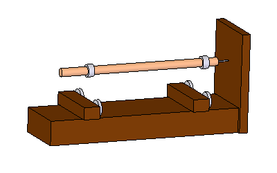
Announcement

Collapse
No announcement yet.

Mechanical Magnetic Torque Amplifier

Collapse
X
 
  • Filter
  • Time
  • Show
Clear All
new posts

  • Newman motor

    Increasing the copper mass and magnet strength will increase the foot pounds of torque in the solenoid piston. An attraction oscillator the size of Joe Neman's "Big Eureka" would drive a train locamotive and run for free just like the big Newman motor. People routinely replicate the Newman spinner but they can't re-create the commutator, that's why we never see any self running Newman motors.


    The solenoid magnet piston beats the switch spring to the top, and the inductive kickback is dissipated during this delay. Tapping back spike from the coil electrodes kills the induction; The current is traveling in the opposite direction!


    Joe Newman's commutator had a section that sidetracked the back spike to a separate destination. The spring pressure switch simply looses it in a hysteresis loop so the output is unadulterated BEMF. Flyback kills induction.

    Comment


    • Newman back spike.

      It"s easy to see how a Newman motor would loop the same way as the attraction oscillator, with a cam lobe and an SPDT micro roller spring pressure switch. The cam lobe would have to be shaped to close the output gates at 17 degrees past TDC to allow time for the inductive kickback to discharge. The remainder of the output would be current traveling in a reverse direction. The back spike we skipped with the connection delay. If you don't detour the back spike, the Newman motor will fail to work because the flyback cancels the induction. The spring release time is equal to or greater then the inductive kickback discharge time in the attraction oscillator. The entire attraction stroke is a pure D.C. pulse. That's all we need to catch. This is free power and in no way effects the torque on piston.
      Last edited by Allen Burgess; 10-21-2018, 01:41 PM.

      Comment


      • Halbach levitation rings.

        How can we run a heavy magnet solenoid on it's side? A very large attraction oscillator could ideally pressurize a hydraulic fluid system and drive a piston like a steam engine. The pressure on the power stroke would be directly proportional to the mass in copper and magnet strength. Let's say we add ten times the copper wire and a ten times stronger magnet. We develop ten times the pressure on the solenoid piston, but the power in and power out remain about even!
        Last edited by Allen Burgess; 10-21-2018, 07:30 PM.

        Comment


        • Mendicino levitator solenoid piston.

          The Mendocino levitator applies pressure to the tip of the axle. Placing a repulsion coil and an electrode on the axle may get it to trigger an SPDT relay with a small battery in the circuit. A resistor would need to be connected between the contacts and the relay to delay the pulse enough to permit discharge of the inductive kickback.


          Two of these power looping Mendocino oscillators running reciprocally, face to face could oscillate a third larger solenoid magnet cylinder in the center perhaps levitated by Halbach rings inside an output coil.
          Last edited by Allen Burgess; 10-22-2018, 05:13 PM.

          Comment


          • all axially magnetized rings; two coils; one hybrid power at the wall, and a second strictly output for the outside magnet.

            this generator would be over unity by exactly the amount of bemf it recovered.

            Last edited by Allen Burgess; 10-22-2018, 06:23 PM.

            Comment


            • The trick to running the "Mendocino levitator attraction oscillator" would simply be to position the SPDT pressure switch with a backing magnet strong enough to depress the switch spring with the attraction force from the axle magnet. The levitator base magnets would need to be extended to cover the throw. Two coils would nest between them, one on each end, the far side exclusively output.
              Last edited by Allen Burgess; 10-23-2018, 01:57 PM.

              Comment


              • Another beautiful solenoid build with a 3 pin SPDT micro roller switch and cam lobe where the third pin is left criminally idle when it could be returning the power pulse.


                https://www.youtube.com/watch?v=ZsJkAys2mHI
                Last edited by Allen Burgess; 10-23-2018, 07:43 PM.

                Comment


                • 3 pin wiring

                  The three pin SPDT basically wires the same way as the four pin because two pins are linked in the four pin leaving three.


                  The hot coil wire would connect to the center pin, in the 3 pin micro roller, the positive of the battery to one side and the positive to out put on the other. The coil hot wire goes to the conjoined pins on the 4 pin pressure switch. A "flip flop": One side on the other off and vice versa

                  The magnitude of the BEMF charge recovery is overwhelmingly abundant. The solenoid motor featured above would go over unity if we wired the switch for output and connected an alternator to the flywheel.
                  Last edited by Allen Burgess; 10-24-2018, 11:09 AM.

                  Comment


                  • Ernshaw's theorem.

                    We can suspend a very large 4" diameter axial polarized cylinder magnet over a Mendocino base with a track length to match the throw. We can attach the other end to a scotch yoke which would limit the return travel of the magnet piston. The return pressure of the "Ernshaw" repulsion spread out over the length of the track bed would transfer more thrust to the piston then the mere attraction of a backing magnet. Half a Mendocino with double the base track magnets, supported on the other end by the flywheel connection.

                    A cam lobe and micro roller SPDT switch on the flywheel would permit the operator to advance the timing to speed it up. Consider how the 3 to 1 sheer to push pull advantage effects the COP.
                    Last edited by Allen Burgess; 10-24-2018, 12:50 PM.

                    Comment


                    • 1st Mendocino levitator;

                      Comment


                      • The spring press SPDT switch shorts the power coil to ground through a load after the power pulse and back spike discharge. The switch delay is long enough to allow the inductive kickback to discharge between contact connection. The back spike is annihilatory current running in the reverse direction. The BEMF output from the Faraday effect of the magnet moving inside the coil is current traveling in the opposite direction to the back spike, from the magnetic field collapse and is much higher in amperage.

                        The SPDT switch does everything this commutator's designed to do: He's just shorting the output directly to ground with no load in between. The BEMF output from this Newman motor would illuminate a bulb, but the tester is not showing that. He's obliquely claiming a 90% pulse recovery:

                        https://www.youtube.com/watch?v=Cx-ECN86D1Y
                        Last edited by Allen Burgess; 10-26-2018, 12:38 PM.

                        Comment


                        • Two switch contacts 4 and 3 are soldered together along with the start wire of the coil. This leaves 3 wires: One switch wire goes to the battery positive the other to the positive electrode of the load in series with the ground. Along with it goes the end wire of the power coil, which connects to negative battery ground too.

                          When the button's depressed the SPDT switch closes and power runs from the positive of the battery through the coil and sends the magnet stack aloft. This frees the switch button and it returns to it's normally closed position after a very brief but significant delay, and shorts the power coil to the battery negative through the load. The attraction stroke is all gravy.

                          Last edited by Allen Burgess; 10-27-2018, 01:23 PM.

                          Comment


                          • The soldering job tightened the oscillator up but the throw decreased. This caused the inductive kickback to show up in the output and no BEMF. I wired my electromagnet in series with the airfare coil and placed the coil over the magnet. I then increased the input with the addition of a second transformer to 2 amps. Thirdly, I increased the strength of the magnet piston. Voila, the throw elongated and the output rose from 1/2 volt to 10 volts.

                            Comment


                            • Tesla size magnet piston.

                              I have close to a Tesla riding now: The EM in series with the air core gives the coils sufficient electro magnetic force to lift the heavy ball magnet off the switch: The magnetic force that raises that heavy Neo sphere, is generated by the 500 Newton electro magnet in series with the air core coil, and the increased magnet strength of the solenoid piston. This increased power did not come at the cost of increased electrical input. The power level of the pulse is controlled at a fixed rate by the wall transformer.


                              https://youtu.be/0upgVOhgOyM
                              Last edited by Allen Burgess; 10-28-2018, 10:08 AM.

                              Comment


                              • Lenz effect.

                                Lenz drag cannot effect the magnet piston in the center of the coil. The coil simply does not project a magnet field into the center of the solenoid; However, the magnet piston's field can effect the windings in the coil wrapped around it.

                                This holds true if the magnet piston throw is to the inside of the magnetic end poles of the solenoid coil.
                                Last edited by Allen Burgess; 11-01-2018, 10:32 AM.

                                Comment

                                Working...
                                X