Announcement

Collapse
No announcement yet.

Mechanical Magnetic Torque Amplifier

Collapse
X
 
  • Filter
  • Time
  • Show
Clear All
new posts

  • Electro-magnet comparison.

    When the "Electro-Magnet" is pulsed, the same field is generated in the coil wether there are permanent magnets attached in attraction or not. The difference is; The permanent magnets reinforce the "Flyback", and invert and transform the output. 100 Newtons of EM force with an equal force in permanent magnet Gauss, will double the "Flyback" as an A.C. sine wave of transformed voltage. The permanent magnets don't act as a resistance against the EM field. The EM field simply fills the available space around them. Flyback load has no effect on input. The EM input is in no way affected by the attached magnets, but the "Flyback" is strengthened. This BEMF output has been carefully measured by the tester, and when built like the prototype, returns the equivalent power of the input pulse. Naturally, a piezo transducer would deliver a C.O.P. of 2. This is a "Free Lunch"!

    The BEMF output from the oscillator with the laminated stator and no magnets attached is a pulsed D.C. of half the power.
    Last edited by Allen Burgess; 12-18-2018, 03:21 PM.

    Comment


    • Submerged ballon metaphor.

      Submerging an air filled balloon will increase the air pressure in the balloon. Attaching permanent magnets to an electro magnet in attraction will increase the "Implosion Pressure" of the BEMF in a similar fashion when current is interrupted. Magnet attraction strength compared to depth of air balloon submergence.

      It doesn't cost anything just to stick a permanent magnet on an Electro-Magnet.
      Last edited by Allen Burgess; 12-18-2018, 03:27 PM.

      Comment


      • Originally posted by Allen Burgess View Post
        When the "Electro-Magnet" is pulsed, the same field is generated in the coil wether there are permanent magnets attached in attraction or not. The difference is; The permanent magnets reinforce the "Flyback", and invert and transform the output. 100 Newtons of EM force with an equal force in permanent magnet Gauss, will double the "Flyback" as an A.C. sine wave of transformed voltage. The permanent magnets don't act as a resistance against the EM field. The EM field simply fills the available space around them. Flyback load has no effect on input. The EM input is in no way affected by the attached magnets, but the "Flyback" is strengthened. This BEMF output has been carefully measured by the tester, and when built like the prototype, returns the equivalent power of the input pulse. Naturally, a piezo transducer would deliver a C.O.P. of 2. This is a "Free Lunch"!

        The BEMF output from the oscillator with the laminated stator and no magnets attached is a pulsed D.C. of half the power.
        I think TinMan was doing that in his rotary Transformer
        Last edited by maxc; 12-18-2018, 04:59 PM. Reason: add letter

        Comment


        • Magnet increasing flyback

          This is a high water mark video: The tester refers to the "Sweet Spot"; This is where the permanent magnet Gauss matches the magnetic core and coil strength. The increased brightness does not increase input draw.

          https://www.youtube.com/watch?v=GRnN7DeYHvU
          Last edited by Allen Burgess; 12-18-2018, 08:20 PM.

          Comment


          • Originally posted by maxc View Post
            I think TinMan was doing that in his rotary Transformer
            Exactly correct.
            Last edited by Allen Burgess; 12-19-2018, 03:18 PM.

            Comment


            • Originally posted by Allen Burgess View Post
              Nice find Allen
              I was doing something similar a number of years ago by wiring relay switches for self-oscillation and lighting LEDs. I never bothered measuring the output, but was always curious about the sparks at the contacts, which were often a green colour, rather than bluish-white.

              There was a young guy on these forums around this time who had built an apparatus using this self-oscillation wiring, dumping the output into caps to drive a load. Through a series of unfortunate circumstances, he left. What struck me was the lack of solid state components in his setup, which I think is a concern with questions of possible EMP occurrences in the future.

              All to say, I think this demo by George Chaniotakis is noteworthy, and I'm glad to see you picked it up. As I said, I believe the same thing can be done with most relay switches as well. I'm interested in seeing how the output might be augmented with magnets.

              All the best!
              Bob

              Comment


              • Bob,

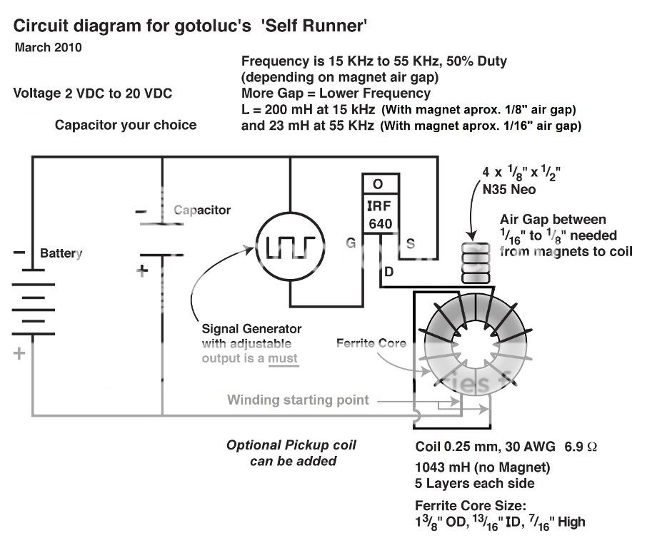
                Compare the joule ringer circuit in the video with gotoluc's self runner circuit;

                Last edited by Allen Burgess; 12-20-2018, 01:26 PM.

                Comment


                • Self Runner

                  @Bob,

                  Good to hear from you again. I believe that it might be possible simply to connect the Oscillator BEMF storage capacitor in parallel to the battery source, like "Luc's" circuit and disconnect the battery positive as Luc does and have the Oscillator continue to self run as Luc's Toroid. I haven't tried this yet, but If it performed that way and generated piezo output, there'd be no reason to ever want to turn it off.
                  Last edited by Allen Burgess; 12-20-2018, 02:45 PM.

                  Comment


                  • Belanger's self runner

                    Look how nearly identical Marc's circuit is to Luc's: Take notice of the magnet and central positioning in adjacency to the twin counter wound coil intersection:

                    https://www.youtube.com/watch?v=QOh1aeIFBXU

                    Both these circuits power self runners but neither generates any physical force from the magnet field oscillation! In both circuits the permanent magnets reinforce the flyback to a level above the input power.

                    I believe the physical oscillation of the magnet armature acts as as secondary feed back.
                    Last edited by Allen Burgess; 12-21-2018, 03:00 PM.

                    Comment


                    • improvement;

                      Galfenol converts energy with high efficiency; it is able to turn roughly 70 percent of an applied mechanical energy into magnetic energy.

                      https://www.youtube.com/watch?time_c...&v=LhRCOWRJV3w
                      Last edited by Allen Burgess; 12-22-2018, 11:49 AM.

                      Comment


                      • Elastic band counter pressure.

                        I rebuilt this version of the oscillator to run with a capacitor in parallel with the power source to see if it will continue to run with the power wire disconnected from the source transformer. Look how the rubber band helps balance the attraction force:

                        https://youtu.be/q6f9FcvIRHo
                        Last edited by Allen Burgess; 12-23-2018, 02:22 PM.

                        Comment


                        • Increased flyback with magnets.

                          I've never seen this demonstrated before!


                          Compare the flyback flashes; First with the magnets attached in attraction to the electromagnet and second; with the magnets detached:

                          https://www.youtube.com/watch?v=kClQviOvywY

                          Comment


                          • Comment


                            • Here's Luc's watermark video of amplifing power by sparking across a Neo magnet. In my video we see an electromagnet attached below the Neo sphere; What effect do you think connecting the electro magnet to the oscillator coil and running a recycling diode across the electrodes would have on the EM force field?: Look at the voltage I'm generating off two 1.5 volt AA batteries in series!

                              The bonus here is that, as I demonstrated in the last video, the magnet not only amplifies the spark, but it strengthens the flyback from the "Electro-Magnet" coil. A third dividend would come from recycling the increased flyback through a diode positioned between the coil wires instead of lighting LED's. It would increase power to send the spark through the Neo magnet on the oscillator armature.

                              https://www.youtube.com/watch?v=wRWwFxNZZxc


                              https://www.youtube.com/watch?v=6BDA...n5ayZlb5K_cwaA

                              What I've been designing here is a speaker in reverse. The oscillator coverts mechanical vibration to electrical power through the "Sono-Battery". This vibration generates electricity. This is the opposite from a speaker that coverts electrical signals into kinetic motion.

                              This version would simply run with an oscillating "Reed Switch". The "Sono-Battery" can convert higher vibration frequencies. We amplify power three ways. One; We send the spark through the magnet. Two; we increase flyback by attaching the magnet to the EM coil. and Three; We recycle this doubled flyback by looping diode. This would jitter a magnet free of charge on a bell tub with a Gafenol hydro coil.
                              Last edited by Allen Burgess; 12-24-2018, 12:59 PM.

                              Comment


                              • Flash camera discharge for sheer pulse.

                                What effect would jolting an electromagnet with a flash camera discharge have on the force field?

                                https://youtu.be/jp-eOLuRLSs


                                Connecting the flash camera circuit to the SPDT oscillator would place the sono vibrator it in "Richter scale" range.
                                Last edited by Allen Burgess; 12-25-2018, 06:32 PM.

                                Comment

                                Working...
                                X