Announcement

Collapse
No announcement yet.

Tom Reed open sourcing his Clem engine design

Collapse
X
 
  • Filter
  • Time
  • Show
Clear All
new posts

  • Tom Reed open sourcing his Clem engine design

    a link back to this thread will be added on Tom's you tube channel.

    https://www.youtube.com/watch?v=nI-lzWfaXcY

    all "respectful" on topic comments welcomed

    }**you tube comments were disabled so as to keep the discussion focused at places where there is more responsible behavior from membership.
    threads will be at Russ's ,Stefan,s and Dansie's forum too

    respectfully
    Chet K
    If you want to Change the world
    BE that change !!

  • #2
    some insight from Tom

    https://www.youtube.com/watch?v=ZD96cTGZDeo&t=333s

    a work in progress .

    Chet
    If you want to Change the world
    BE that change !!

    Comment


    • #3
      some quotes..

      First you need the Patent...
      It was filed, by whom and when is the question.


      "at the requisite +300 degrees F.."

      Bernoulli's principle?

      "It consisted of a cone mounted on a horizontal axis. The shaft which supported
      the cone was hollow and the cone had spiralling channels cut into it. These
      spiralling pathways wound around the cone terminating at the cone base in the
      form of nozzles (rimjets)."

      "When fluid was pumped into the hollow shaft at pressures ranging from
      300-500 PSI (pounds per square inch), it moved into the closed spiralling
      channels of the cone and exited from the nozzles. This action caused the cone to
      spin. As the velocity of the fluid increased, so did the rotational speed of the
      cone."

      "As the speed continued to increase, the fluid heated up, requiring a heat
      exchange and filtering process. At a certain velocity, the rotating cone became
      independent of the drive system and began to operate of itself. The engine ran
      at speeds of 1800 to 2300 RPM"

      "it generated a consistent 350 HP for 9 consecutive days which astounded the
      engineers at Bendix. They concluded the only source of energy which could
      generate this much power in a CLOSED SYSTEM over an extended period
      must be of an atomic nature.
      Construction of the engine was from off the shelf components except for the
      hollow shaft and the custom cone with the enclosed spiral channels."

      "With regard to differences between the CEACU design and Clem the CEACU
      does not require the cone, but instead uses a thick disk with nozzles on the
      outer edge. A hollow shaft feeds water into this disk at a high velocity."

      Reported:
      "even the drawing you have on your site is one of the
      very first crude drawings and by no means the ending result."

      "As I remember the engine was self running, but you needed the starter just to
      start the engine initially. I helped my dad do the drawings and the writings for
      submission to the patent office but by no means do I know how it works."

      "One thing you must remember there was so much information that my dad kept
      in his head and refused to submit it to the patent and other people because of
      the bomb threats we had against our lives. But there are daily detail logs of
      what he was doing and the problems he ran into. Our house was set on fire
      several times and I have even seen my dad beat to a pulp and dropped in our
      drive."

      "A Patent was filed and received and is renewed as needed"

      "One last thing that I will say before I go is that the machine is not buried
      somewhere and still running. And the prototype car was just junk that if I'm
      not mistaken was just hauled off and scrapped."

      ">>> It was under another name. Which I do not care to release at this time."


      "He also used a heat exchanger to keep it cool"

      I think I read some-where 10 years or more ago
      someone said he used 6 or 7 "pumps/stage's"..

      Comment


      • #4
        yes a deep mystery indeed

        Tom feels phase change and perhaps cavitation play a part ,

        powering the Tornado effect [a vacuum] which manifests in his recent experiments.

        and to be perfectly clear
        cavitation needs more eyes on [contribution from member Microvolt here]

        http://aflb.ensmp.fr/AFLB-342/aflb342m669.pdf

        respectfully
        Chet K
        If you want to Change the world
        BE that change !!

        Comment


        • #5
          At first glance this motor reminds me of two primitive motors; a pulse jet and a themojet. However a lot of information is out which I was previously unaware.

          KeelyNet - Clem Engine Index Page - 07/18/13
          http://www.keelynet.com/clemenginehammer.pdf
          KeelyNet - Final Clem Photos - 07/10/13

          Because of a previous post I feel intense need to preach: The Clem Motor is the Anti-Christ.

          To begin with the Clem motor would be re-creating fundamentals which drive Universe, and inside a box as a closed cycle; which would show that mass, inertia, and gravity are not intrinsic properties of matter, and that's a problem. Any kind of demonstration to that effect is an explosive and dangerous proof contradicting the foundations of education, science, and all authority: It won't be tollerated, not lawfully anyways. Forget patents lest ye forget the tombstone trodden path.

          I'll be frank and brief. Any reference to the Clem Motor creating a nuclear kind of reaction is likely not un-intentional: Excuse to prohibit.

          IMOP, an overunity device must interact in the dynamically field of space in such a way that is, by accident or design, either reducing the mass of the componets, or otherwise altering the surrounding immediate space by distorting otherwise normal laws of physics, which would otherwise hold true inside a limited area of the surrounding space, and so as to then be in an advantageous position to the enery input, or otherwise to enter into the surrounding immediate space by virtue of it's movements, mechanical and electrical, such that these interactions then replicate some form of known means, however unexplained, which extract energy from the surrounding space.

          I will have to look at this thing in more detail since it isn't what I thought it was from the primitive drawings I'd previously seen. This is considerably more complex based on the information I've found due to this thread and wanting to make a response to it. Lastly, be aware and be safe. Meaning that whatever quote "new information" we now get should not be assumed to be free and clear of suspicion. While some work for freedom, shills and artificial intelligence work for slavery since neither has any eithical or moral convictions.

          Oh yes, btw...thanks; it's nice to see your work on this.
          Wouldn't want you to have the wrong idea.
          Last edited by Gambeir; 11-07-2017, 01:38 AM.
          "The past is now part of my future, the present is well out of hand." Joy Divison "Heart and Soul LP."

          Comment


          • #6
            The simplified Clem Engine of Donnie Watts

            [VIDEO]https://www.youtube.com/watch?v=whoSCaF196w[/VIDEO]

            Code:
            https://www.youtube.com/watch?v=whoSCaF196w
            The simplified Clem Engine of Donnie Watts - YouTube

            I thought this was interesting.

            U.S. Patent #3,697,190

            https://patentimages.storage.googlea.../US3697190.pdf

            Donnie Watts Patent Application #CA2025601A1
            https://patents.google.com/patent/CA...r=Donnie+Watts


            Abstract
            ROTOR POWER CONVERSION APPARATUS AND METHOD

            Abstract of the Disclosure An apparatus for converting fluid flow and pressure into rotational mechanical power at high efficiency, has a hollow pressure-tight rotor with central fluid entrance and radial fluid passages, thrust-jets, a rotor support and bearing means and a fluid supply. The thrust-jets extend from the rotor and impart tangential reaction thrust or torque to the rotor by ejecting fluid approximately tangential to the arc described by the rotor's rotational motion, the thrust being always relative to its point of origin and continuously amplified by the increase in fluid pressure within the rotor due to the enforced rotation of the fluid together with the rotor and the centrifugal force acting on the fluid coincidental to its rotational motion. The rotor has rigid axles attached along its axis of rotation, at least one of the axles being hollow to admit fluid. In one embodiment the rotor is suspended over a fluid reservoir by a solid upper axle with bearings and support frame while the hollow lower axle extends downward from the rotor into the fluid supply beneath the rotor from which fluid enters the rotor through a sealed rotating hollow joint channelling fluid from the bottom of the reservoir via a feed pipe within the reservoir. The upper axle extends through low friction bearings on the upper support frame to provide a power take-off whereby mechanical power may be transmitted by gears, pulleys or the like. Rotor speed governors, an air purging mechanism and a shut-off mechanisms are provided. A method for operating the apparatus is described.
            Last edited by vidbid; 11-07-2017, 06:35 PM.
            Regards,

            VIDBID

            Comment


            • #7
              an update from Tom

              would seem the Tornado takes shape .


              https://www.youtube.com/watch?v=dHI-...ature=youtu.be

              respectfully

              Chet
              If you want to Change the world
              BE that change !!

              Comment


              • #8
                Just want to offer a couple thoughts on this interesting engine and the interpretations I've seen so far.

                Two key parts to a pulse jet are reed valves and a harmonically tuned exhaust pipe. Whereas in a pulse jet motor the reed valves control the influx of ram air. This would imply that the intake should have an inlet valve (reed valve) and that the cone shape to the Clem motor may also be a kind of tuned pipe *harmonically configured, which is the way a pulse jet exhaust pipe is configured to operate. It is the harmonics of the reverse flow after the discharge at the back end of a pulse jet which relieves the reed valve in the face of pulse jet to close and for new fuel to be injected and ignited, thus repeating the cycle.

                I would think that if there is a connection (in thought) between a pulse jet motor design and the Clem Engine, then the fluid pickup on the Clem motor is controlled by a tuned harmonic back flow in order to obtain the optimal rate of discharge from the exiting jets, and that the intake of fluid is thus controlled by harmonic back flow. I can see that sort of thinking in the water ram configuration of this motor, but don't yet see anyone whose yet considered this notion. There might be a reed valve at the intake to the motor, but I haven't thought this through in how this might all work in a vacuum.

                A ram jet and pulse jet work on air pressure and harmonics. This is working in a vacuum: Well I've got to mull that concept over for a while but there seems to be a lot of sense going on with that idea. Not sure this egg is hatched just yet: Interesting.
                Last edited by Gambeir; 11-11-2017, 02:34 AM.
                "The past is now part of my future, the present is well out of hand." Joy Divison "Heart and Soul LP."

                Comment


                • #9
                  Re: The Donnie C. Watts invention - part 1

                  I see that you folks have made mention of the Donnie Watts device.

                  I had noticed, some time ago, that the Donnie Watts invention had been written up by Patrick J Kelly on page 14 of the following online document:
                  http://free-energy-info.com/Chapter4.pdf
                  The article is titled as The Centrifugal Energy Amplification Conversion Unit (“CEACU”) of Donnie Watts.

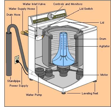
                  I found the description of this device to be quite interesting. Unlike the Clem engine, Donnie's device is a relatively simple build, but has amazing potential. When I started reading Donnie's description of the CEACU, it occurred to me that much of what is needed for such a project could be obtained from a discarded clothes washing machine. A washing machine, as we all know, has an outer cabinet, a pump, an electric motor, and a drum (actually a rotatable drum within a stationary drum), which is supported upon a shaft and bearing assembly. Inside the center of the drum there is an agitator, which is fitted to the central shaft, but the agitator would be removed to expose the drive shaft. There are two basic movements within the wash cycle, and these are either a back and forth motion of the agitator, or a rapid spin of the drum and agitator to squeeze water out of the clothes, which the pump then forces out of the machine into a standing drain pipe. Instead of wasting liquid down the drain, however, a CEACU build would continuously recycle the liquid by attaching the drain hose to the top of a hollow shaft coupling which feeds liquid to the CEACU rotor. If you have ever opened the lid of a washing machine during a spin cycle then you will have realized that the motor is quite capable of spinning a heavy drum full of clothes and water at a respectable rpm, so there is no question that it could provide enough drive power to run a suitable pump for a CEACU build. The washing machine pump does seem to be able to evacuate the water from the drum rather quickly, so it might be suitable for the CEACU build, but if a higher capacity pump is needed then that's a relatively easy modification. The motor, of course, doesn't need to spin anything other than the pump, as it is the liquid jets on the rotor that propel the rotor. Conversely, though, once the rotor has attained enough speed to become a self runner, the motor could be utilized as a 110 volt AC power generator if desired. The typical electric motor found in a washing machine is 1/2 horsepower, though some machines have a 3/4 horsepower motor. While a 1/2 horsepower motor would only produce around 373 watts when used as a generator, which doesn't seem like much, keep in mind that if running 24 hours a day this would equal nearly 9 kilowatts a day, or 270 kw in a 30 day month, and could save you around $25 on your electric bill if you are paying around 9.5 cents per kwh. Of course you could do a lot better than that by making use of a commercial generator head.

                  In a CEACU build, since there is no need to spin the drum, the drum would remain stationary, and the drive shaft which the agitator is mounted on will be desired to always turn in one direction of rotation rather than in a back-and-forth motion as when washing clothes. These changes would be rather easy to make by reconfiguring the belt drive system so that the drive shaft is directly belted to the electric motor. Not all washing machines use a belt drive system nowadays, as manufacturers have been changing their designs over to a direct drive from the motor to a transmission, as well as to the pump. Still, even with the direct drive machines it seems evident that many of the washing machines parts could be utilized. Even if the only part you make use of is the drum, that's still a great start for a CEACU build. Anyways, if you can't quite picture this washing machine idea, perhaps this cutaway diagram of a washing machine will help you visualize what's already there, and what little extra would need to be added.


                  As you can see, the drum is fairly large. In a standard size machine like my Maytag top loading washer it measures about 17 inches from top to bottom, and about 21 inches inside diameter. That's enough room to mount a CEACU rotor of any size from 10 inches to 20 inches diameter. The above linked CEACU write-up says that a 10 inch rotor will develop about 10 horsepower, and that doubling the rotor size will produce 4 times as much, so 40 horsepower if the rotor is 20 inches. As one wouldn't need 40 horsepower to generate enough power to service a household, I'd suggest perhaps building a 16 inch diameter rotor, and this would afford enough clearance space between the rotor and drum to experiment with the employment of spray deflector vanes such as seen in the Patrick Kelly write-up and copied below.


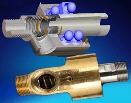
                  The rotor would be mounted upon a hollow shaft that would need to be coupled to the central drive shaft (hidden by the Agitator in the above diagram) that will drive the AC motor as a generator, or drive an optional generator head such as the one pictured in the write-up. The pump would feed liquid collecting in the bottom of the tub back up to the top of the hollow rotor shaft, through a shaft coupling of the type shown at the end of Patrick's write-up and copied below.
                  Last edited by rickoff; 02-15-2018, 09:32 PM.
                  "Seek wisdom by keeping an open mind to alternative realities, questioning authority, and searching for truth. Only then, when you see or hear something that has 'the ring of truth' to it, will it be as if a veil has been lifted, and suddenly you will begin to hear and see far more clearly than ever before." - Rickoff

                  Comment


                  • #10
                    Re: The Donnie C. Watts invention - part 2

                    Really, the most work-time in creating a CEACU build in this manner would be in preparing the hollow shaft, and building the rotor, and while this would be somewhat time consuming the rotor design is actually very simple. Basically, the rotor is simply two circular discs, with four V-shaped pieces placed between the discs to form spokes, and a band encircling the outer perimeter so that you have a sealed unit. Donnie says that a 4 foot diameter CEACU would have its sides 6 inches apart, so in scale a 16 inch rotor would have its sides just 2 inches apart. Donnie suggests using 1/8 inch sheet metal in constructing the rotor, but of course other options exist and the material itself isn't that important. What's important is to follow Donnie's directions. If you read those instructions carefully, you will notice three important things about the jets to be attached to the outer perimeter of the rotor:
                    1. The size of these jets should be quite small. Donnie says about the size of a football inflation needle, or about 1 and 1/2 millimeter. The reason why small size jets should be used is because it allows a high pressure to build up inside the rotor, and that inside pressure is the most important aspect.
                    2. The spray jets should be "slanted sharply to one side," as Donnie says. The reason for this, as I see it, is that by slanting the spray pattern off to the side, rather than keeping it straight along the plane of the perimeter, an advancing jet is not being saturated with spray from the jet which preceded it, which of course would create a resistance as well as much turbulence. In the washing machine build, the jets should of course be slanted somewhat toward the lower disc of the rotor (downwards) to send the spray where you want it to collect at the bottom of the drum. I'd say that a 25 degree offset from horizontal would probably be sufficient.
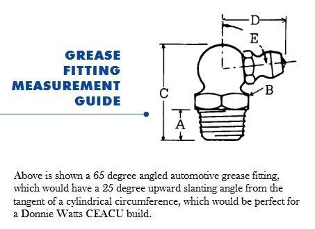
                    3. The jets should also have a 25 degree angle relative to the tangent of the rotor. If a hole is bored straight into a point along the rotor's perimeter, that hole would be 90 degrees to the tangent. If a 90 degree elbow fitting were used as a spray jet, the spray would be at zero degrees to the tangent, so whatever is used as a jet must have its spray ejection angled 25 degrees higher. Now here's an idea that springs to mind - why not use 65 degree 1/4-28 grease fittings as the spray jets? To convert the grease fittings to spray jets you simply remove the ball and spring. The size of the spray would be small like Donnie suggests, and a 65 degree fitting (which is measured from the vertical as angle E in the below diagram) brings it to 25 degrees above the tangent.


                    You will also note that Donnie suggests using automatic transmission fluid (ATF) rather than water for the fluid to be sprayed, and this makes perfect sense for two reasons:
                    1. The ATF would lubricate the bearings very nicely, and open bearings create much less resistance to rotation than sealed bearings.
                    2. In states which have harsh winters you wouldn't want to use a liquid that could freeze, so ATF is a great choice. Of course any hydraulic fluid, such as brake fluid or hydraulic jack oil would work equally well, but might be more expensive than ATF.

                    At the very end of the CEACU write-up there is a link provided to view a video of an actual CEACU build that was done by Geoffrey Miller.
                    You will notice that the build is somewhat similar to the type of build that I'm suggesting, as the rotor is mounted horizontally in a cylindrical steel tub. You will also notice, however, that the rotor is only about 8 inches in diameter and that the spray jets appear to be somewhat large 90 degree brass elbows which are not oriented at a downward angle. Thus, the build does not conform to Donnie's specifications, and yet Geoffrey says that it does perform as a self-runner, so think how much better it might function if built according to Donnie's specs. Geoffrey appears to believe that because this rotor starts spinning very quickly this is a desired factor, but Donnie says that in the correct build the rotor will start slowly and then continuously accelerate. Larger size nozzles make the rotor start up faster, but create a need for a much higher volume of liquid to be passing through them, and thus a much higher capacity pump. I'm not suggesting that Geoffrey's build isn't a good one, of course, I'm just saying that it doesn't employ some of the features which Donnie says are essential to an optimum build. Geoffrey has a great workshop and has built replications of many interesting devices, and also has patents on some energy multiplying devices of his own. Seeing that his CEACU build works is a good indication that building to Donnie's specs should definitely result in success.

                    The ring of plates circling the rotor, and affixed to the tub in Geoffrey's build, may well help give the spray jets more driving force, and this was also noted in the write-up as being the case, but even if no such plates are included the rotor would spin very nicely, and this is easily proven by examining a very early likeness of this rotor/jet design, which is the Aeolipile, a.k.a. Heron's Ball. The builder of this small replica says it will spin at 1500 rpm with only 1.8 psi of steam, and I have heard of larger replications attaining upwards of 18,000 rpm. There's no need to attain such a speed in a CEACU, of course. Donnie says that the air bubbles in the liquid start separating from the liquid and forming air pockets in the V-shaped pieces between the "spokes" at around 60 rpm. The unit can't become a self-runner until the air pockets have been fully formed and become compressed due to pressure from the in-flowing liquid. One important factor to keep in mind is that the amount of liquid outflow through the jets should never reach more than 66 percent of the inflow, so that must be considered when determining how many jets should be utilized, as well as the size of the hollow shaft and the rotor feed holes bored into it.
                    Last edited by rickoff; 02-15-2018, 10:01 PM.
                    "Seek wisdom by keeping an open mind to alternative realities, questioning authority, and searching for truth. Only then, when you see or hear something that has 'the ring of truth' to it, will it be as if a veil has been lifted, and suddenly you will begin to hear and see far more clearly than ever before." - Rickoff

                    Comment


                    • #11
                      Re: The Donnie C. Watts invention - part 3

                      I was able to locate the Canadian patent application (CA 2025601) details for the Donnie Watts device, and this was found at
                      PatentÂ*2025601Â*Summary - Canadian Patents Database

                      Click on the above link to open the website, click the Documents button, scroll down until you see the items list, click to check-mark the first 6 open boxes, and then click the blue Download bar, above the list, to download a zipped archive of the checked items.

                      Donnie, a U.S. citizen, applied for a patent on this device along with a Canadian fellow named T. Edwin Orton. The application date was September 18, 1990. I'd guessed that Donnie had also filed for a U.S. patent a year earlier than this, because the Patrick Kelly write-up concerning Donnie's invention said that Donnie had filed on September 25, 1989, but I have been unable to locate any records of a U.S. patent application submitted by Donnie. After reading the Canadian patent information, it is clear that both this patent application and the Patrick Kelly write-up were in regards to essentially the same device, although the Canadian patent application shows some further developed design features. The text description in the Canadian application is also a bit more elaborate than what Patrick Kelly had found and shared, and also featured more diagrams.

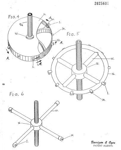
                      The "Drawings" pdf file, on page 4, shows three differing rotor styles (Figures 4, 5, and 6), all of them different than what was pictured in Patrick's write-up.


                      The Figure 4 rotor is the most similar one to what was shown by Patrick, but in comparing them you will see that there are two distinct revisions:
                      1. The four V-shaped internal pieces which formed "spokes" are gone, and have been replaced by curved strips which run from the center hub to the perimeter of the rotor. This separates the interior of the rotor into as many sections as the number of spray jets that are employed. I suspect that the reason this change was made was to prevent the liquid from sloshing around the rotor's perimeter at start-up, and the curvature of these strips, which curve clockwise towards the direction the rotor is advancing from, helps to trap inflowing liquid close to each spray jet.

                      2. An additional item (#34 in the drawing) has been added at the outer perimeter of the rotor, between each spray jet. This item is a poppet valve, and the purpose of these valves is to govern the speed of the rotor to maintain a desired rpm. These would have to be adjusted to open when the internal pressure acting upon them reaches a pressure that yields the desired speed. These valves are designed to spill liquid straight out, in a radial direction, so that the liquid being expelled does not add to the rotational force caused by the spray jets. Of course a control valve on the liquid supply line would also be utilized to initially set a limit on the amount of liquid entering the rotor, and thus the poppet valves would simply act to maintain the desired speed by maintaining a constant internal pressure. When both the main control valve and the poppet valves are adjusted correctly, there would be little spillage from the poppet valves. Conversely, if the poppet valves were constantly spilling fluid at the desired rpm then the main control valve would need to be closed down a bit.

                      The optional rotor design shown in figure 5 shows tubular "spokes" fastened between the inner hub and an outer tubular ring, while the figure 6 rotor uses elongated tubular spokes and eliminates the figure 5 outer ring. It should be obvious that the figure 6 rotor would be the easiest one to build, as it could be fashioned from equal lengths of steel pipe having end caps, and tightened into threaded holes in the center hub. While this design may or may not be as effective as the figure 4 rotor, which would have the advantage of using multiple spray jets, it would be well worth building to test in initial trial runs. A machine shop could prepare the center hub at reasonable cost, and that would be a smart way to go because you would want to have the holes bored and tapped precisely so that you'd end up with a well balanced rotor. In this design, you'd install a spray jet at one side of each of the pipe end caps, and a poppet valve at the center tip of the end caps. You could use straight grease fittings, with the ball and spring removed, as the spray jets, or you could even use sports ball inflation needles, which I believe have a straight 5/16 inch thread at the attachment end. Optionally, you could simply drill a small hole in the side of each end cap without even attaching a spray nozzle. In any case, you would want to drill all the end cap holes as precisely as possible, so if you don't have a drill press and a jig to hold and align the caps then farming this step out to a machine shop would be a good idea. The best way to determine exactly where to drill the spay jet holes in the end caps would necessitate assembling and tightening the pipes into the center hub and then tightening on the end caps, as the holes must be aligned properly when all is tightened. When assembling the pipes and end caps to the hub, use Teflon tape wrapped around the threads. If you do go with the inflation needles, you would need to cut the tip ends off to remove the side holes in those needles so that the spray is ejected straight out instead of some of it being wasted to the sides. The trick would be in cutting them without crimping them, so of course you wouldn't want to use nippers. Using a very fine blade saw such as you'd find in an Exacto knife kit would be a safer bet, and then you'd want to deburr the opening. If you choose to use nippers for the job, it would be wise to first insert a solid copper wire into the needle so that the needle will not distort when cut. The copper wire can then be pushed out of the needle orifice. AWG size 15 copper wire is 1.45 millimeter diameter, so is very close to the 1.5 mm size inside diameter of a ball inflation needle if that is a correct measurement rather than a guesstimate.

                      By the way, in determining the cross sectional size of the pipes used for a figure 6 rotor, the Canadian patent application says that the size should be at least 8 times the cross sectional orifice size of the spray jets. This ensures that adequate liquid supply and pressure is always maintained at the spray jets.

                      One other modification found in the Canadian patent application is shown in figure 7 of the Drawings file, and this is meant to purge any air that might collect near the hub. Any air bubbles in the fluid would tend to be forced toward the hub rather than the rotor's perimeter, and as the air collects there it would interfere with free flow of incoming liquid. In the old design, air was supposed to collect within the V-shaped pockets to keep it away from the "spokes," but the newer design changes may indicate that the earlier design wasn't as effective at separating air as it was thought to be. The last thing you would want in the liquid would be air bubbles, of course. Perhaps filling the rotor to capacity, at pressure, before allowing it to turn, and incorporating a simple bleeder valve at the hub, similar to a brake bleeder valve, would be a sufficient means of expelling all trapped air. It works well enough in a hydraulic brake system.
                      Last edited by rickoff; 02-15-2018, 08:53 PM.
                      "Seek wisdom by keeping an open mind to alternative realities, questioning authority, and searching for truth. Only then, when you see or hear something that has 'the ring of truth' to it, will it be as if a veil has been lifted, and suddenly you will begin to hear and see far more clearly than ever before." - Rickoff

                      Comment

                      Working...
                      X