Announcement

Collapse
No announcement yet.

Radiant Pulse Charging to Condition Lead Acid Battery

Collapse
X
 
  • Filter
  • Time
  • Show
Clear All
new posts

  • #46
    Hi all, at the moment, i guess i'm experimenting with different oscillator setups to try and get the most efficiency.
    This latest circuit, if we subtract the .3 amps showing as idle current on my power supply, this circuit is 76 percent efficient.
    Of course that does not include the flyback capture into the 12 volt charge battery.
    If we assume at least 50 percent recovery, that might be a 1.14 coefficient.
    Here is latest circuit.
    Thoughts welcome.
    peace love light

    Comment


    • #47
      Hi all, I'm working on a new coil to use.
      I have twelve bolts wound with 24awg. magnet wire to use for a 12 strand coil.
      I also made a paper tube core/coil former, so i can slide in a ferrite tube if i want to test with core or without.
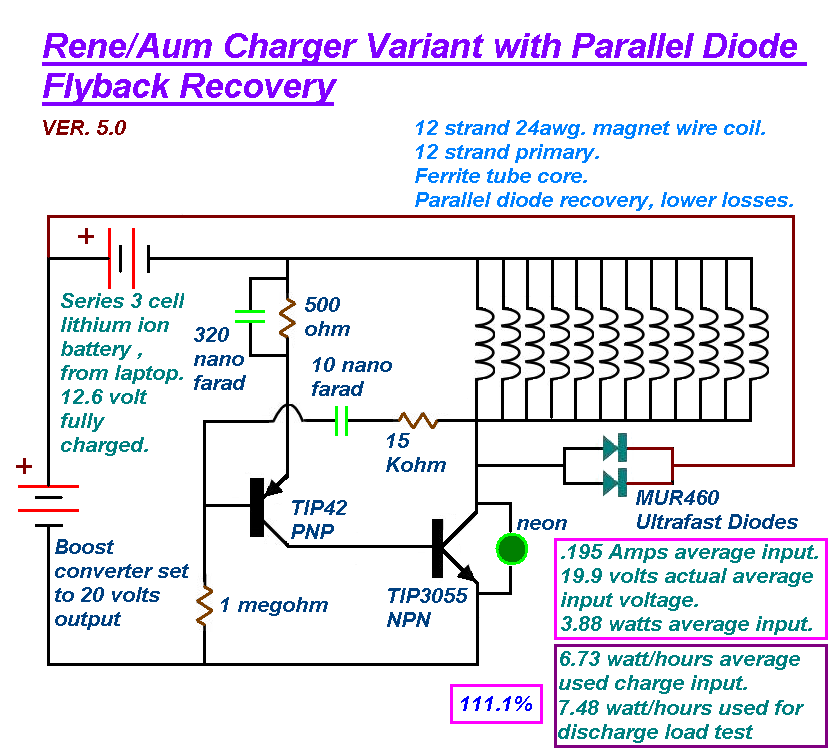
      The idea, is to use 1 strand for oscillator feedback, 2 strands in parallel for oscillator primary and the other 9 strands for experimenting with different secondary wiring arrangements.
      One thing i want to try, is wiring all 9 parallel strands in series, to see if any solid state analogy can be achieved, like turions series, multistrand mechanical generator, that speeds up under load.
      Thoughts welcome.
      peace love light

      Comment


      • #48
        Hi all, here's a pic of the new 12 strand coil with core and the previous coil for size difference.
        peace love light

        Comment


        • #49
          Hi all, been testing the new 12 strand coil.
          I tested the 2 strand primary, with 3 sets of 3 strands in series, with each series set to its own diode, then into charge battery, that worked ok
          Then made another test, i placed the 3 series sets in parallel, into a single diode, then into the charge battery, that worked a little better maybe.
          Next test, i wired all 11 strands in parallel, then a single diode from collector into charge battery.
          That makes a total 272 milliohms primary coil resistance or less.
          This wiring configuration has worked the best so far, at 31 volt input power supply.
          All these comparison tests were tuned to a very similar input wattage.

          Other wiring configurations to try, 2, 4, or 6 strands in parallel as oscillator primary, then 9, 7 or 5 strands in parallel as secondary with diode into charge battery.
          Another test might be multiple parallel primary strands, with a varied number of secondary strands in series, though a full wave bridge into a different load other than a battery.
          peace love light
          edit: am testing 4 parallel strand primary and 7 parallel strand secondary with single diode into charge battery and it seems to have even better charging at 31 volt input. Though it seems the higher input voltage of 50 volts does seem more efficient.
          Last edited by SkyWatcher; 04-03-2018, 11:28 PM.

          Comment


          • #50
            Hi all, i went back to 50 volt input and yes, the efficiency is higher.
            About 75 percent of the power goes through the circuit and into the 12 volt charge battery, compared to around 53 percent using the 31 volt input.

            I do wonder if going even higher in input voltage would increase the efficiency further.
            And it does not seem to matter if the ferrite core is used or not, the higher voltage allows more of the input power to flow through the circuit.

            Maybe the higher voltage allows the short pulses to saturate the copper coil material to a greater degree and this enables more current to flow per pulse, giving greater efficiency, or maybe i should say, the coil reaches a closer to steady state, non changing magnetic field, thus less counter emf to impede current flow in the given time of each pulse.
            Or, we also have a little bit of the Joseph Newman effect, where the copper atoms are aligned more efficiently with the higher voltage.

            Does this make sense to anyone observing this thread, thoughts appreciated.

            peace love light
            Last edited by SkyWatcher; 04-04-2018, 07:00 PM.

            Comment


            • #51
              Hi all, update on large coil tests.
              I'm using all 11 strands in parallel as the oscillator primary in this latest test, with 2 diodes in parallel off the collector of transistor to 12 volt charge battery and using the ferrite tube core.
              I am now using my 400 watt boost converter as the input power supply, so i can raise the voltage even further to test any efficiency increases.

              When using an input voltage of 50.6 volts from power supply, the efficiency is 72.5 percent, of course not including flyback recovery, actual voltage shown flowing through oscillator is around 35 volts.

              On this latest test, using 60.1 volts from power supply, the efficiency has increased to
              77.5 percent, actual voltage shown flowing through oscillator is around 46 volts.

              These tests are tuned to use close to the same input wattage, by adjusting resistor values in oscillator circuit.
              I find these results promising, i will continue to raise the voltage by 10 volt increments and tune and share the data with you folks.
              I think this boost converter can only reach around 90 volts though.
              Comments welcome.
              peace love light

              Comment


              • #52
                Large coil higher voltage test update

                Hi all, the results at 70.2 volts dc input, is showing increased efficiency.

                The actual voltage through oscillator circuit is 57.2 volts at .07 amps.

                That is 4 watts flowing through the circuit into the charge battery and 4.91 watts being input.

                Efficiency is now 81.5 percent, not including flyback recovery.
                peace love light

                Comment


                • #53
                  Hi all, latest test using 80.2 volts dc input.

                  The efficiency of the circuit has increased further.

                  It has increased to 84 percent.

                  Actual voltage through oscillator is 67.4 volts.

                  Current flowing through circuit is .06 amps.

                  Also had to wire another neon in series with neon across transistor collector, because the higher voltage was causing it to conduct.

                  I also have a capacitor in parallel with each of the resistors shown in the circuit drawing, it helps to adjust frequency and lower input.

                  Also, I'm finding the circuit to charge very efficiently, have been using a 12 volt led bulb to discharge the 12 volt battery and observing watt hours used, then can compare to watt hours placed back in and so on.

                  peace love light
                  Last edited by SkyWatcher; 04-08-2018, 12:50 AM.

                  Comment


                  • #54
                    Hi all, have been posting at the other forum, thought i would share my latest circuit.
                    peace love light

                    Comment


                    • #55
                      Hi all. I’ve probably built around fifty joule thief circuits over the last 8 yrs or so, always with about 3-100 ma input and up to about 40 ma return to source at the same input voltage, using single stage transistors. Recently I thought I’d try some tip 122/127 Darlingtons with 12v input and was surprised to see 400-600 ma return to source current.i haven’t measured the input current. I’m guessing it would be 750-1000ma for that sort of output. Heat gets a bit serious if I push it any harder.
                      The tips seem happy with 1 k base resistance off the usual variable voltage divider and they need a decent heat sink. With the much increased output I decided to hack a battery charger and fit the additional circuitry inside the box with a little computer fan on top in a bid to restore a car battery that was digitally tested as bad:replace, The built in magic eye indicator for one cell of the battery had no colour to begin with and after about a week is starting to show the bright green. Still waiting for the red dot in the Centre tho. Anyway long story short, it might be worth trying tip122/127 for more output. Hfe 1000-2500, 100v, 5a continuous.
                      Cheers.
                      Attached Files
                      Last edited by voltan; 11-12-2018, 12:02 AM. Reason: Dislexia

                      Comment

                      Working...
                      X