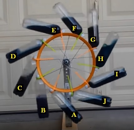
First of all, please note that the first image shown below is not my concept for an overbalance water wheel. It comes from another discussion thread on this forum which I had visited because of my interest in the topic of discussion. I originally began posting ideas for an overbalanced water wheel concept in the Bhaskara's Wheel thread, which had been started in October 2016 as a poll to determine whether or not the claims of an experimenter, who had claimed his wheel would rotate continuously, was real or fake. His build, simply a bicycle wheel with half-filled soda bottles tied to the perimeter, is seen below.


The experimenter had put up a YouTube video claiming to show the wheel turning non-stop for 5 minutes. It didn't take long to determine that the claims were false, as Peter Lindemann suggested by doing a quick center of gravity analysis. I concurred with Peter's analysis, and after studying the YouTube video there was no doubt whatsoever that the experimenter had posted a hoaxed video. As I mentioned in post #9 of the Bhaskara's Wheel thread, I noticed that there were two recurring chirping sounds (a higher pitched one followed by a lower pitched one 2.5 seconds later. This may have been a bird outside the garage, and it is not all that unusual for a bird to make two differing pitched chirps close together. What I did find unusual, though, was the fact that when I timed the interval starting immediately upon hearing the high pitched chirp, and ending immediately after each successive high pitched chirp, it always timed out at 19.6 seconds during this 5 minute run. This, of course, is pretty much a dead giveaway that the video was edited to loop within that 19.6 second time frame, which could have started at the chirp or anywhere in between chirps.
Although the video was obviously hoaxed, and there was no way that the above shown water wheel could possibly rotate on its own, there were two things about the build that interested me - the angular placement of the soda bottles, and the sloshing effect of the liquid each time a bottle was inverted. I saw how these two elements could be utilized for true overbalance rotation in a perfected water wheel design, and set about making some drawings to illustrate the concept that came to mind.
After submitting several concept drawings within the Bhaskara's Wheel thread, I decided it would be best to start a new thread for this concept. Since the wheel initially being discussed in the Bhaskara's Wheel thread was quickly proven to be a hoax, I thought that readers would tend to exit the thread quickly without staying long enough to review what I was explaining further on. Thus, I'll leave one last post in that thread to steer anyone interested in my concept design to this new thread where I will fully share all details about the evolution of this overbalance water wheel.
I started out with a basic concept, which involved moving all the water on the right side of the wheel inward by utilizing a channel at the wheel's perimeter, dividing that channel into sections using barriers, and attaching a tube to the side of each section by means of a 90 degree elbow fitting. The below drawing shows how that would work each time the tube was inverted during rotation.


The layout of the wheel itself, for the above configuration, is shown in the next drawing, with the dotted lines representing the baffles that would divide the perimeter into 12 enclosed sections which would feed water out to a tube as rotation brought a tube out over the top of the wheel, and then act as a receiver for water emptying from a tube as the tube lifted above the horizontal plane when rising from the bottom of the wheel.


I then showed how the wheel would look with the tubes attached and partially filled with water. As you can see, while this is definitely a huge improvement over the soda bottle experiment, there was still much room for further improvement. While the 4 tubes (A, B, C, and D) on the left side of the wheel would definitely provide overbalance to more than 4 perimeter sections on the right side, the question remained as to whether those 4 tubes on the left side were capable of overbalance to the entire water weight found on the right side (2 tubes plus 6 perimeter sections).


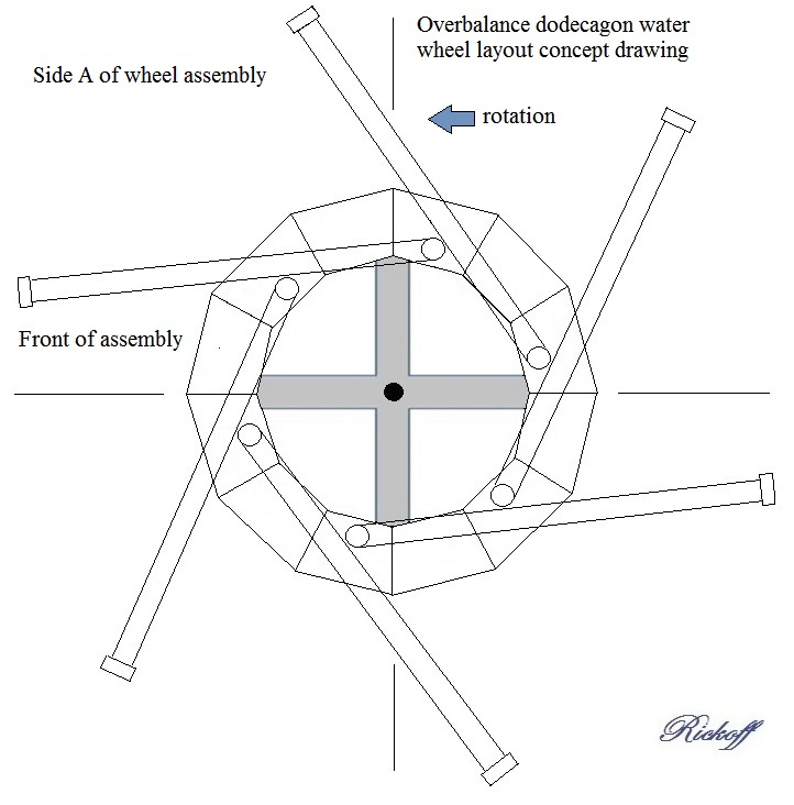
It appeared evident that, in order to obtain counter-clockwise rotation, I would need to increase the angularity of the tubes so that tube L would lay downward enough to occupy the space shown occupied by tube A. This would allow tube L to be filled at this stage of rotation, while tube F would already have emptied its water back into the perimeter. The only way to achieve those positive changes would of course require having only six tubes on the side of the wheel. I still wanted 12 tubes, and to keep that configuration only required moving six of the tubes to the opposite side of the wheel and attaching them to perimeter sections that would be unoccupied. Thus the 12 tubes would alternate from one side to the other every 30 degrees along the perimeter. This could be done with a one wheel or two wheel build, but I felt that a single wheel build would have the advantage of being more cost efficient. I also determined that, for ease of building such a wheel, I should scrap the idea of constructing water tight perimeter sections in favor of a far simpler solution that would bring water at the right side of the wheel's perimeter even further inward. My idea for the improved concept was to redesign the wheel to be built as a 12 sided polygon, which is called a dodecagon. The next drawing shows the configuration for side A of the wheel.


Side B of the wheel is similarly constructed, keeping in mind that the tubes are positioned 30 degrees apart from those on side A, along with the fact that the tubes appear reversed because you are observing the reverse side.


These side A and side B layouts requires longer tubes than shown in the previous drawing, in order to extend a similar amount beyond the perimeter, but at the same time there is twice the amount of tube laying on the face of the dodecagon, and that coverage is mostly centered further inward towards the axle. What this means, of course, is that each tube can act as its own feeder and receiver, and that the tubes only need be connected to the dodecagon section bore holes, while each dodecagon section is simply a flat board. All that remained was to provide a drawing showing the tubes with water fills for both sides of the wheel at once, and to determine the available torque at both sides of the center line so as to show whether or not an overbalance condition could actually be achieved. In my next post I will show such a drawing and explain how I obtained my calculations.
Best to all,
Rick

The experimenter had put up a YouTube video claiming to show the wheel turning non-stop for 5 minutes. It didn't take long to determine that the claims were false, as Peter Lindemann suggested by doing a quick center of gravity analysis. I concurred with Peter's analysis, and after studying the YouTube video there was no doubt whatsoever that the experimenter had posted a hoaxed video. As I mentioned in post #9 of the Bhaskara's Wheel thread, I noticed that there were two recurring chirping sounds (a higher pitched one followed by a lower pitched one 2.5 seconds later. This may have been a bird outside the garage, and it is not all that unusual for a bird to make two differing pitched chirps close together. What I did find unusual, though, was the fact that when I timed the interval starting immediately upon hearing the high pitched chirp, and ending immediately after each successive high pitched chirp, it always timed out at 19.6 seconds during this 5 minute run. This, of course, is pretty much a dead giveaway that the video was edited to loop within that 19.6 second time frame, which could have started at the chirp or anywhere in between chirps.
Although the video was obviously hoaxed, and there was no way that the above shown water wheel could possibly rotate on its own, there were two things about the build that interested me - the angular placement of the soda bottles, and the sloshing effect of the liquid each time a bottle was inverted. I saw how these two elements could be utilized for true overbalance rotation in a perfected water wheel design, and set about making some drawings to illustrate the concept that came to mind.
After submitting several concept drawings within the Bhaskara's Wheel thread, I decided it would be best to start a new thread for this concept. Since the wheel initially being discussed in the Bhaskara's Wheel thread was quickly proven to be a hoax, I thought that readers would tend to exit the thread quickly without staying long enough to review what I was explaining further on. Thus, I'll leave one last post in that thread to steer anyone interested in my concept design to this new thread where I will fully share all details about the evolution of this overbalance water wheel.
I started out with a basic concept, which involved moving all the water on the right side of the wheel inward by utilizing a channel at the wheel's perimeter, dividing that channel into sections using barriers, and attaching a tube to the side of each section by means of a 90 degree elbow fitting. The below drawing shows how that would work each time the tube was inverted during rotation.

The layout of the wheel itself, for the above configuration, is shown in the next drawing, with the dotted lines representing the baffles that would divide the perimeter into 12 enclosed sections which would feed water out to a tube as rotation brought a tube out over the top of the wheel, and then act as a receiver for water emptying from a tube as the tube lifted above the horizontal plane when rising from the bottom of the wheel.

I then showed how the wheel would look with the tubes attached and partially filled with water. As you can see, while this is definitely a huge improvement over the soda bottle experiment, there was still much room for further improvement. While the 4 tubes (A, B, C, and D) on the left side of the wheel would definitely provide overbalance to more than 4 perimeter sections on the right side, the question remained as to whether those 4 tubes on the left side were capable of overbalance to the entire water weight found on the right side (2 tubes plus 6 perimeter sections).

It appeared evident that, in order to obtain counter-clockwise rotation, I would need to increase the angularity of the tubes so that tube L would lay downward enough to occupy the space shown occupied by tube A. This would allow tube L to be filled at this stage of rotation, while tube F would already have emptied its water back into the perimeter. The only way to achieve those positive changes would of course require having only six tubes on the side of the wheel. I still wanted 12 tubes, and to keep that configuration only required moving six of the tubes to the opposite side of the wheel and attaching them to perimeter sections that would be unoccupied. Thus the 12 tubes would alternate from one side to the other every 30 degrees along the perimeter. This could be done with a one wheel or two wheel build, but I felt that a single wheel build would have the advantage of being more cost efficient. I also determined that, for ease of building such a wheel, I should scrap the idea of constructing water tight perimeter sections in favor of a far simpler solution that would bring water at the right side of the wheel's perimeter even further inward. My idea for the improved concept was to redesign the wheel to be built as a 12 sided polygon, which is called a dodecagon. The next drawing shows the configuration for side A of the wheel.

Side B of the wheel is similarly constructed, keeping in mind that the tubes are positioned 30 degrees apart from those on side A, along with the fact that the tubes appear reversed because you are observing the reverse side.

These side A and side B layouts requires longer tubes than shown in the previous drawing, in order to extend a similar amount beyond the perimeter, but at the same time there is twice the amount of tube laying on the face of the dodecagon, and that coverage is mostly centered further inward towards the axle. What this means, of course, is that each tube can act as its own feeder and receiver, and that the tubes only need be connected to the dodecagon section bore holes, while each dodecagon section is simply a flat board. All that remained was to provide a drawing showing the tubes with water fills for both sides of the wheel at once, and to determine the available torque at both sides of the center line so as to show whether or not an overbalance condition could actually be achieved. In my next post I will show such a drawing and explain how I obtained my calculations.
Best to all,
Rick


 And since 1 hp is equivalent to 0.7457 kilowatt, this means the 6" build would only be capable of producing about 0.04 kilowatt, or 40 watts. At that rate, you could produce just shy of 1 kilowatt hour(kwh) of electric power in 24 hours. Does this mean that it wouldn't be worth building the wheel? Well, it would run 24 hours a day, 365 days a year, so looking at it that way you could generate roughly 365 kwh each year. If you currently pay 10 cents per kwh to the electric company, you could save $36.50 per year. At that rate it would probably take a few years to break even on the cost of building the water wheel. Of course you might be paying 25 cents per kwh by that time, so in that case you'd then be saving $91.25 at that point. That might be worthwhile, since of course as rates go up you'd be saving more and more, but it's definitely not exactly what I would have hoped for with a 6" pipe scale build.
Comment