We have had zero degree mornings here for 4 days now, and 3 of those days the temperature never went above 20. This afternoon the temperature rose to a balmy 30 degrees. This seems more like January weather than November weather. We also had some snow earlier in the week. It would be nice if we could get a little global warming coming our way, but I don't expect that to happen. Farmer's Almanac says we're in for a hard winter, and they are right about 80% of the time.
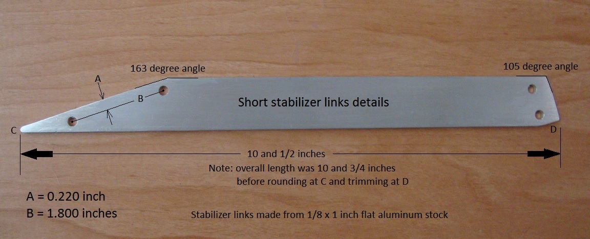
I have been working on the stabilizer links, and have completed the two longer ones. Here's a photo showing the details for these links.

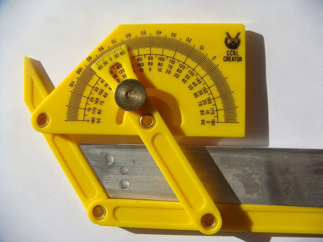
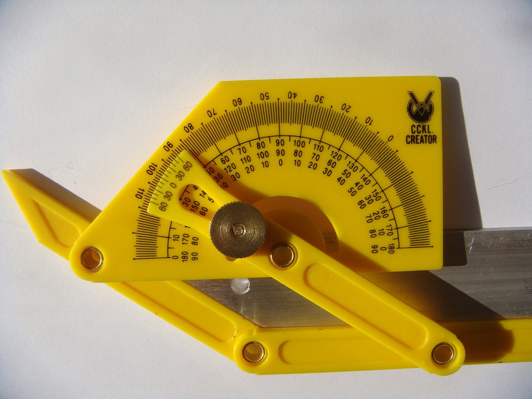
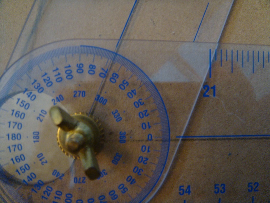
After attaching one of the uprights to its footing anchor, I placed the 16 inch side of a carpenter's square upon the base, and moved the 24 inch side up against the upright to position it perfectly vertical, and tightened the #10-24 x 5/8 attachment screw and nut to maintain that position. Having already cut the 1/8 x 1 inch flat aluminum stock to the correct length and angles for attachment, I held the stabilizer link in the desired position and then poked a black sharpie marker pen through the holes in the link anchor, and the existing mid-point hole in the upright, to mark the link for its hole locations. I then carefully center-punched the markings using a hammer and awl, and drilled the holes using my benchtop drill press and a 3/16 inch drill bit. The holes may look a bit rough in the photo, and that is because I took the photo before slightly chamfering the hole edges. You will notice that there is an extra hole at the anchor end of the link shown in the below photo, and that's because I used a piece of stock which I had already drilled for use with another fixture. Both links also have a hole near their mid-points, but I "photo-shopped" the above link photo to remove the extra holes so that I wouldn't be confusing anyone. The below photos show the angle details for both ends of the long links. The anchor end of the link is cut at a 123 degree angle, while the upright attachment end is cut at a 146 degree angle.
I have been working on the stabilizer links, and have completed the two longer ones. Here's a photo showing the details for these links.

After attaching one of the uprights to its footing anchor, I placed the 16 inch side of a carpenter's square upon the base, and moved the 24 inch side up against the upright to position it perfectly vertical, and tightened the #10-24 x 5/8 attachment screw and nut to maintain that position. Having already cut the 1/8 x 1 inch flat aluminum stock to the correct length and angles for attachment, I held the stabilizer link in the desired position and then poked a black sharpie marker pen through the holes in the link anchor, and the existing mid-point hole in the upright, to mark the link for its hole locations. I then carefully center-punched the markings using a hammer and awl, and drilled the holes using my benchtop drill press and a 3/16 inch drill bit. The holes may look a bit rough in the photo, and that is because I took the photo before slightly chamfering the hole edges. You will notice that there is an extra hole at the anchor end of the link shown in the below photo, and that's because I used a piece of stock which I had already drilled for use with another fixture. Both links also have a hole near their mid-points, but I "photo-shopped" the above link photo to remove the extra holes so that I wouldn't be confusing anyone. The below photos show the angle details for both ends of the long links. The anchor end of the link is cut at a 123 degree angle, while the upright attachment end is cut at a 146 degree angle.








Comment