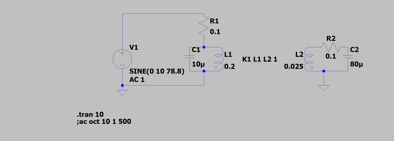
Cool to see a new topic on an old video! Vidbid try this circuit in ltspice, works much better. (While less interactive than Falstad simulator it is a great deal more accurate).

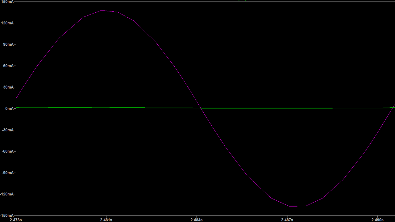
Pink wave form is current through the R2 (output), green is current through R1 (input). As you can see the green is negligable and is only topping up what is lost in the LC. Pink on the other hand is alive and well.

The circuit parameters (L/C) are quite different from what Armagdn03 used in his video but the concept he has shown in that video holds for all resonant circuits.
I encourage you to play with the spice directive for the coupling of the coils (change the 1 in "K1 L1 L2 1" to any number between 1 and 0) then re-tune with the AC Analysis tool, as well as changing the inductance and capacitance of the primary and secondary sides while maintaining the same resonant frequency (an easy was to do this is doubling inductance and halving capacitance or visa versa) and observe the changes in amplitude between the primary and secondary. Some interesting observations can be made there.
I've attached the spice model to help speed up the process of playing.
On a slightly different note, I sent you a skype message the other day Armagdn, not sure if you got it but letting you know just in case you didn't.

Pink wave form is current through the R2 (output), green is current through R1 (input). As you can see the green is negligable and is only topping up what is lost in the LC. Pink on the other hand is alive and well.

The circuit parameters (L/C) are quite different from what Armagdn03 used in his video but the concept he has shown in that video holds for all resonant circuits.
I encourage you to play with the spice directive for the coupling of the coils (change the 1 in "K1 L1 L2 1" to any number between 1 and 0) then re-tune with the AC Analysis tool, as well as changing the inductance and capacitance of the primary and secondary sides while maintaining the same resonant frequency (an easy was to do this is doubling inductance and halving capacitance or visa versa) and observe the changes in amplitude between the primary and secondary. Some interesting observations can be made there.
I've attached the spice model to help speed up the process of playing.
On a slightly different note, I sent you a skype message the other day Armagdn, not sure if you got it but letting you know just in case you didn't.

 ) but I can see some obstacles getting it to work how you've described. I am open to being wrong and have been on many an occasion. I look forward to hearing how your experiment goes! The one question I will ask is this, is a resistor the best load for this type of circuit?
Comment