Announcement

Collapse
No announcement yet.

The bistander thread

Collapse
X
 
  • Filter
  • Time
  • Show
Clear All
new posts

  • altrez
    replied
    Originally posted by RAMSET View Post
    Altrez
    I was also going to take a run at this work/replication [Dave had sent some info ] with help from Ciftfa
    been very busy with other FE related open source things ATM
    however
    I can forward you some funds to help cover some costs [thru a PM here.. Amazon Gift card or Visa etc gift card ?
    However I recently found these don't work out of US ?? paypal does work globally but I will not attach my banking info to them. [ I can text or write amazon etc gift card number in US and funds are delivered totally anonymous to recipient [both parties remain anonymous .
    I have been trying to sort a method for sending Paypal overseas with no account attached [just a gift card... ...but how to send as gift card ??

    thank you regardless ...and I will remove this message if [for any reason]
    But funding open source experiments globally and anonymously is important topic ATM [and one reason for this comment ....how to send paypal with no bank info attached ?]

    much gratitude

    Chet K
    PS edit for Posters name above [sorry for confusion

    hmm seems edits for Adding Altrez name to top don't work or only readable when I sign in here?
    RAMSET "Chet K"

    Thank you so much for your kind offer! At this time I have all the funds I need to replicate this work. With that being said, I am very humbled by your offer. It's members like you that keep the dream of Free and Unlimited energy for the people of this world a possibility.

    My Sincere Thanks,

    -Altrez
    Leave a comment:


  • Turion
    replied
    Altrez,
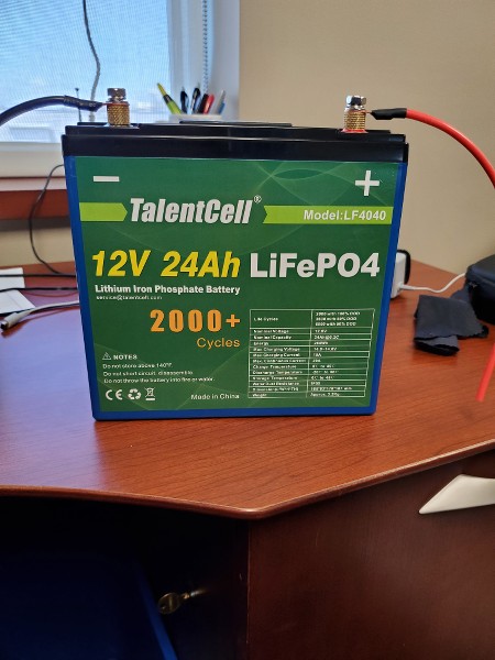
    Hope the BMS on that battery will allow charging and discharging at the same time. I had one that wouldn’t and ended up buying a BMS that is used in solar systems where they understand the need for both at the same time.

    Leave a comment:


  • RAMSET
    replied
    Altrez
    I was also going to take a run at this work/replication [Dave had sent some info ] with help from Ciftfa
    been very busy with other FE related open source things ATM
    however
    I can forward you some funds to help cover some costs [thru a PM here.. Amazon Gift card or Visa etc gift card ?
    However I recently found these don't work out of US ?? paypal does work globally but I will not attach my banking info to them. [ I can text or write amazon etc gift card number in US and funds are delivered totally anonymous to recipient [both parties remain anonymous .
    I have been trying to sort a method for sending Paypal overseas with no account attached [just a gift card... ...but how to send as gift card ??

    thank you regardless ...and I will remove this message if [for any reason]
    But funding open source experiments globally and anonymously is important topic ATM [and one reason for this comment ....how to send paypal with no bank info attached ?]

    much gratitude

    Chet K
    PS edit for Posters name above [sorry for confusion

    hmm seems edits for Adding Altrez name to top don't work or only readable when I sign in here?
    Last edited by RAMSET; 07-11-2020, 04:19 PM.

    Leave a comment:


  • altrez
    replied
    I got my new battery in yesterday for testing the one battery system. It is really nice.


    The first round of testing will start today.

    -Altrez

    Leave a comment:


  • altrez
    replied
    Originally posted by bistander View Post

    From Amazon customer review"
    "High overcharging voltage with LiFePO4 battery.
    I bought this from Amazon along with a Shorei LiFePO4 battery for my motorcycle. These types of batteries require a charge voltage of 3.6v per cell, or 14.4v for a 12 volt battery. The specs on this charger say that bulk charge is at a constant 2.0 amps until voltage reaches 14.1 volts. I connected the charger to my battery, along with a voltmeter on the leads, and watched as bulk kept climbing until I finally disconnected the charger at 15.0 volts. That is way too high and would lead to damage to my expensive battery. Had I not checked with a voltmeter, I could have installed the battery in my motorcycle, next to its gas tank, and would have left it unattended while charging. The thought of a possible lithium ion thermal runaway in my garage, next to a tank of gasoline, has given me good cause to return this charger. If you buy one, check it with a voltmeter."

    Don't burn down your house.
    bi
    Yeah I saw that but its got 77% 5 star reviews so I am okay with it. I will defiantly check it while testing.

    -Altrez

    Leave a comment:


  • bistander
    replied
    Originally posted by altrez View Post

    Hello Bistander,

    I thought it looked like an M6 type. I picked Dork as I have several of their gadgets lying around including smaller boost converters. Never had an issue with Dork products. The battery's are nice and can be used in other projects as well. What did you think about the chargers?

    -Altrez
    From Amazon customer review"
    "High overcharging voltage with LiFePO4 battery.
    I bought this from Amazon along with a Shorei LiFePO4 battery for my motorcycle. These types of batteries require a charge voltage of 3.6v per cell, or 14.4v for a 12 volt battery. The specs on this charger say that bulk charge is at a constant 2.0 amps until voltage reaches 14.1 volts. I connected the charger to my battery, along with a voltmeter on the leads, and watched as bulk kept climbing until I finally disconnected the charger at 15.0 volts. That is way too high and would lead to damage to my expensive battery. Had I not checked with a voltmeter, I could have installed the battery in my motorcycle, next to its gas tank, and would have left it unattended while charging. The thought of a possible lithium ion thermal runaway in my garage, next to a tank of gasoline, has given me good cause to return this charger. If you buy one, check it with a voltmeter."

    Don't burn down your house.
    bi

    Leave a comment:


  • altrez
    replied
    Originally posted by bistander View Post

    Hi Altrez,
    looks like M6, maybe M5 threaded terminals. Appears screws are included.
    The Dork unit is called a regulator. It may be different than a boost converter. I'd have to see schematics. A regulator may be isolated whereas a converter will not. The manual won't display on this device. Besides that reviews are not very good. Personally I've been pleased with the product or two I've gotten from them.
    ​​
    regards,
    bi
    Hello Bistander,

    I thought it looked like an M6 type. I picked Dork as I have several of their gadgets lying around including smaller boost converters. Never had an issue with Dork products. The battery's are nice and can be used in other projects as well. What did you think about the chargers?

    -Altrez

    Leave a comment:


  • bistander
    replied
    Originally posted by altrez View Post
    Okay Guys this is what I ordered.

    3 of theses battery's for the 3BS tests:
    https://smile.amazon.com/gp/product/...?ie=UTF8&psc=1

    This battery for the One battery test:
    https://smile.amazon.com/gp/product/...0?ie=UTF8&th=1

    These 2 chargers:
    https://smile.amazon.com/gp/product/...?ie=UTF8&psc=1
    https://smile.amazon.com/gp/product/...?ie=UTF8&psc=1

    And this boost converter:
    https://smile.amazon.com/Numerical-R...%2C168&sr=8-18

    Anything else I can get off Amazon for this project? Not sure what type of battery terminals the one big battery has any ideas?

    Thanks for all the help everyone.

    -Altrez
    Hi Altrez,
    looks like M6, maybe M5 threaded terminals. Appears screws are included.
    The Dork unit is called a regulator. It may be different than a boost converter. I'd have to see schematics. A regulator may be isolated whereas a converter will not. The manual won't display on this device. Besides that reviews are not very good. Personally I've been pleased with the product or two I've gotten from them.
    ​​
    regards,
    bi

    Leave a comment:


  • altrez
    replied
    Okay Guys this is what I ordered.

    3 of theses battery's for the 3BS tests:
    https://smile.amazon.com/gp/product/...?ie=UTF8&psc=1

    This battery for the One battery test:
    https://smile.amazon.com/gp/product/...0?ie=UTF8&th=1

    These 2 chargers:
    https://smile.amazon.com/gp/product/...?ie=UTF8&psc=1
    https://smile.amazon.com/gp/product/...?ie=UTF8&psc=1

    And this boost converter:
    https://smile.amazon.com/Numerical-R...%2C168&sr=8-18

    Anything else I can get off Amazon for this project? Not sure what type of battery terminals the one big battery has any ideas?

    Thanks for all the help everyone.

    -Altrez

    Leave a comment:


  • bistander
    replied
    Originally posted by Turion View Post
    Attached is a circuit.
    Testing goes like this.
    Charge your battery. Let it rest. Measure it with a battery analyzer.
    Attach a MATT MODIFIED MOTOR turning another (stock) motor as a generator directly to a battery. Put a full wave bridge on the output of the generator and connect a 12 volt Light bulb to it as a load with a kilowatt meter between the FWB and the load. Run the battery down to 12.2 volts. Let the batteries rest, and measure the batteries. That gives you a baseline output in power to the load as recorded by the kilowatt meter. YOU ALSO NEED TO KEEP TRACK OF THE TIME THE SETUP RAN.

    Now charge the battery back up to where it was. Let it rest, and then test and record with a battery analyzer. The problem with comparing one setup to another is the starting energy in the battery and the ending energy in the battery. Hard to accurately compare.

    Then run the first attached circuit. You run it until the total OUTPUT to the load is exactly the same as what the previous circuit put out. Then you stop the test, let the batteries rest for the same amount of time you did in the previous test, and measure the batteries with the battery analyzer. Compare what was in the batteries at the end of the two tests where you produced the exact same amount of power to the load as measured by the kilowatt meter. You can also record the time of the test run, but it's NOT important.

    The third step, which is far more difficult to measure, is to run the SECOND circuit I am attaching. You can still run the load, but whether the light is brighter than with the previous test, or dimmer is hard to tell. It's had to get an accurate measurement of what goes into the load as voltage and amperage change over the course of the run. You can measure the TEMPERATURE of BOTH the load in the previous test and the load in this test with an infrared heat gun

    https://www.amazon.com/Etekcity-Lase...s%2C507&sr=8-3

    and log when the temp of the load drops below a certain point that was set as the "run" temperature by the previous test. If the load is running at a higher temperature, you can kind of ASSUME that more energy is going through it. Here is where your recorded TIME for the first run comes in. If the load runs at a higher temperature for longer than it did in the first test, has more power gone through the load?" Some will argue that it has NOT, and may have good reasons for that argument, but I know of no other way to compare when voltages and amperage aren't consistent. You can't simply put a kilowatt meter on it and measure the input to the load. You can't multiply volts times amps when both fluctuate, so unless you have some really good data logging equipment, this is the only way I know to have a reasonable idea. When the run. time exceeds the run time in the baseline test, stop the test, let the batteries rest and measure the battery.

    On these circuits there is a + line going out of the battery to the BOOST MODULE and a + line going INTO the battery. That + line IN needs a diode in it and I forgot to put it in the drawing.
    Just to save this post from modification or deletion. I may experiment with parts of it and want it in tact.
    bi

    Leave a comment:


  • altrez
    replied
    Originally posted by bistander View Post

    Hi Altrez,

    I have a fair amount of experience with LiFePO4. While that battery may be a good one, I would not recommend it for the test that Turion just outlined. He doesn't specify battery type for his test, but he bases some actions on voltage. The LiFePO4 cell, and therefore battery, has a much different voltage vs SOC (State of Charge) than PbAcid. I'm sure you can find and compare discharge characteristic curves for the two types.

    Whatever battery you use, I suggest that you first test it to the manufacturer specifications. I've tested hundreds if not thousands of batteries over the years and have found a substantial number of stinkers as delivered new whether from the factory or from retailer.

    Good luck,
    bi

    {edit} Just been researching (Google) that LiFePO4 battery (ExpertPower) and cannot find detailed technical data.I did notice that special charger is needed.
    Thank you fo the information I have had a lot of new bad batteries as well.

    Leave a comment:


  • bistander
    replied
    Originally posted by altrez View Post
    A friend recommend this battery as a good starting point.

    https://smile.amazon.com/ExpertPower...s%2C169&sr=8-2

    What do you guys think?

    -Altrez
    Hi Altrez,

    I have a fair amount of experience with LiFePO4. While that battery may be a good one, I would not recommend it for the test that Turion just outlined. He doesn't specify battery type for his test, but he bases some actions on voltage. The LiFePO4 cell, and therefore battery, has a much different voltage vs SOC (State of Charge) than PbAcid. I'm sure you can find and compare discharge characteristic curves for the two types.

    Whatever battery you use, I suggest that you first test it to the manufacturer specifications. I've tested hundreds if not thousands of batteries over the years and have found a substantial number of stinkers as delivered new whether from the factory or from retailer.

    Good luck,
    bi

    {edit} Just been researching (Google) that LiFePO4 battery (ExpertPower) and cannot find detailed technical data.I did notice that special charger is needed.
    Last edited by bistander; 07-08-2020, 02:44 PM. Reason: Added info

    Leave a comment:


  • altrez
    replied
    A friend recommend this battery as a good starting point.

    https://smile.amazon.com/ExpertPower...s%2C169&sr=8-2

    What do you guys think?

    -Altrez

    Leave a comment:


  • Turion
    replied
    Attached is a circuit.
    Testing goes like this.
    Charge your battery. Let it rest. Measure it with a battery analyzer.
    Attach a MATT MODIFIED MOTOR turning another (stock) motor as a generator directly to a battery. Put a full wave bridge on the output of the generator and connect a 12 volt Light bulb to it as a load with a kilowatt meter between the FWB and the load. Run the battery down to 12.2 volts. Let the batteries rest, and measure the batteries. That gives you a baseline output in power to the load as recorded by the kilowatt meter. YOU ALSO NEED TO KEEP TRACK OF THE TIME THE SETUP RAN.

    Now charge the battery back up to where it was. Let it rest, and then test and record with a battery analyzer. The problem with comparing one setup to another is the starting energy in the battery and the ending energy in the battery. Hard to accurately compare.

    Then run the first attached circuit. You run it until the total OUTPUT to the load is exactly the same as what the previous circuit put out. Then you stop the test, let the batteries rest for the same amount of time you did in the previous test, and measure the batteries with the battery analyzer. Compare what was in the batteries at the end of the two tests where you produced the exact same amount of power to the load as measured by the kilowatt meter. You can also record the time of the test run, but it's NOT important.

    The third step, which is far more difficult to measure, is to run the SECOND circuit I am attaching. You can still run the load, but whether the light is brighter than with the previous test, or dimmer is hard to tell. It's had to get an accurate measurement of what goes into the load as voltage and amperage change over the course of the run. You can measure the TEMPERATURE of BOTH the load in the previous test and the load in this test with an infrared heat gun

    https://www.amazon.com/Etekcity-Lase...s%2C507&sr=8-3

    and log when the temp of the load drops below a certain point that was set as the "run" temperature by the previous test. If the load is running at a higher temperature, you can kind of ASSUME that more energy is going through it. Here is where your recorded TIME for the first run comes in. If the load runs at a higher temperature for longer than it did in the first test, has more power gone through the load?" Some will argue that it has NOT, and may have good reasons for that argument, but I know of no other way to compare when voltages and amperage aren't consistent. You can't simply put a kilowatt meter on it and measure the input to the load. You can't multiply volts times amps when both fluctuate, so unless you have some really good data logging equipment, this is the only way I know to have a reasonable idea. When the run. time exceeds the run time in the baseline test, stop the test, let the batteries rest and measure the battery.

    On these circuits there is a + line going out of the battery to the BOOST MODULE and a + line going INTO the battery. That + line IN needs a diode in it and I forgot to put it in the drawing.
    Last edited by Turion; 07-08-2020, 05:55 AM.

    Leave a comment:


  • BroMikey
    replied
    Originally posted by Turion View Post
    Nope. I use a lithium iron battery. A supercap might be a good choice though. I can't say, since I have never owned one.
    Me gonna get both, Thanks Dave. I have converters galore. Probably I will show Jordan during this new school year coming up so watch for the potential difference testing. I guess just hook it up like the battery?

    Leave a comment:

Working...
X