Announcement

Collapse
No announcement yet.

Bedini's cap pulser

Collapse
X
 
  • Filter
  • Time
  • Show
Clear All
new posts

  • #16
    Hi Dave,

    what I would like to know is what machine was used in the specific TUV test a the bottom of this link:

    http://www.tuks.nl/Mirror/Bedini/joh...nibearden.html

    regards,
    mario

    Comment


    • #17
      Originally posted by Mario View Post
      Hi Dave,

      what I would like to know is what machine was used in the specific TUV test a the bottom of this link:

      http://www.tuks.nl/Mirror/Bedini/joh...nibearden.html

      regards,
      mario
      Hi Mario I honestly don’t know.

      Comment


      • #18
        Originally posted by jettis View Post
        Hello Mario, Here is a link from wayback machine in the TUV testing…

        https://web.archive.org/web/20220114...TUV/42TUV.html

        I was wrong, the machine in the TUV test is, as shown in the video’s, exactly the same machine as in the pictures above. I will look for my vids and report back, like I said earlier.

        Dave Wing
        That's what I thought!

        Couldn't think of another one that could have been it.

        And you can see for the test he's just using small maybe 4-5 Ah gel cells.

        Rather than COP 12.0, I kind of recall the TUV showed something like COP 5.0.
        Last edited by Aaron; 01-20-2024, 06:12 AM.
        Sincerely,
        Aaron Murakami

        Books & Videos https://emediapress.com
        Conference http://energyscienceconference.com
        RPX & MWO http://vril.io

        Comment


        • #19
          So the info that's been on John's sites for ages about the tuv test is wrong?

          http://www.tuks.nl/Mirror/Bedini/john1/bearden.html

          regards,
          Mario

          Comment


          • #20
            Mario,

            Can you quote what on that page might be wrong so nobody has to re-read the entire thing to see what you are referencing?
            Sincerely,
            Aaron Murakami

            Books & Videos https://emediapress.com
            Conference http://energyscienceconference.com
            RPX & MWO http://vril.io

            Comment


            • #21

              Hi Aaron,

              I'm not saying it's wrong. I've always been intrigued by the results of the chart below. This info has been for decades on John's sites and lately I came across the info that there was an EFV film showing just that, meaning the TUV tests. That's why I asked were it was available, but according to Dave which saw the movie, it doesn't show a 1:12 machine which I find odd. All I would like to know is what machine gave the results shown below and maybe see a picture or the film of it.

              regards,
              Mario


              TUV Testing Labs

              BATTERY TEST FOR THE BEDINI MOTOR GENERATOR


              DATE : OCTOBER 13, 2000
              BATTERY TEST SEQUENCE:
              One lead acid gel-cell (12 volts, 450 milliamps) is being utilized as the primary source fully charged at 12.5 volts.
              Three (3) lead acid gel-cell batteries (12 volt, 450 milliamps) strapped in parallel are being used as the charge destination. The batteries are discharged to 10 volts for the test purposes.
              Test #1 starts at 10:45 AM utilizing primary battery fully charged at 12.5 volts charging three (3) destination batteries paralleled. The destination batteries reach a charge capacity of 14 volts at 11:20 AM.
              The destination batteries are then discharged to 10 volts under working load to prepare for Test #2.

              Test #2 starts at 11:25 AM utilizing primary battery measured at 11.5 volts. Charging three (3) destination batteries paralleled. The destination batteries reach a charge capacity of 14 volts at 12:50 PM.

              The destination batteries are then discharged to 10 volts under working load to prepare for Test #3.

              Test #3 starts at 1:00 PM utilizing primary battery measured at 10.5 volts. Charging three (3) destination batteries paralleled. The destination batteries reach a charge capacity of 14 volts at 1:40 PM.
              The destination batteries are then discharged to 10 volts under working load to prepare for Test #4.

              Test #4 starts at 2:05 PM utilizing primary battery measured at 9.5 volts. Charging three (3) destination batteries paralleled. The destination batteries reach a charge capacity of 13 volts at 2:40 PM. The primary battery is now discharged to 9 volts under working load and unable to further run the Bedini motor generator.

              TOTAL BATTERIES CHARGED:

              12 lead acid gel-cell batteries (12 volts, 450 milliamps each). This ratio is a 12 to 1 charging factor. The motor operation (work) being performed as this was done is not included as an additional factor in this test.


              Comment


              • #22
                Been 24 years about so not 100% sure.

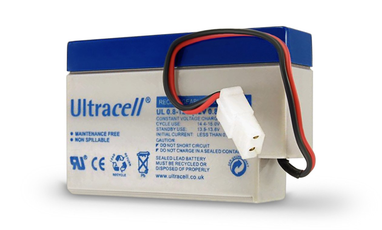
                What is 450 milliamps? It is stated for both the input and output batts. Milliamp hours? .45 Ah? What kind of gel is that small if that is even what it means. Or is that the rated discharge based on a 20 hour rating, which is what the Ah rating printed on the battery would be and that would be 9Ah but the closest size battery to that for a gel cell are the 12v 7ah batteries, not 9, which John used a lot. That would be identical to my scooter battery so still not sure what 450 ma refers to. Thought it might be the draw to run the SG but again, it's mentioned for the output battery as well.

                That's not too clear but the best guess is that the exact SG shown in the pics above is the unit used for these tests for TUV.

                It's the only one I can think of that was ever pictured as part of any of the TUV tests.

                That test is straightforward enough - seems anyone can try to replicate it (the process, maybe not the results) with gel cells and a small SG cap dump build. Thinking about it, I don't recall anyone trying to replicate this particular kind of test.
                Sincerely,
                Aaron Murakami

                Books & Videos https://emediapress.com
                Conference http://energyscienceconference.com
                RPX & MWO http://vril.io

                Comment


                • #23
                  Hi Aaron,

                  I think it's 450mAh. Looking at the pics of the test the size looks like it.

                  ENGINEER FRANK HENSEL FROM TÜV SAN DIEGO'S OFFICE


                  regards,

                  Mario


                  ​​​​​​​

                  Comment


                  • #24
                    Can you find any online that fit that capacity? I did a quick search and didn't find anything.

                    This image shows size of the 12v 7ah gel.

                    Taking away all the extra casing, terminals, etc. can 15.5 of those battery plates fit roughly into the 7ah body? Even close?

                    It's possible. In any case, that test could be tried with whatever the smallest SLA that can be found.

                    7ah12vgel.jpg
                    Last edited by Aaron; 01-22-2024, 10:17 PM.
                    Sincerely,
                    Aaron Murakami

                    Books & Videos https://emediapress.com
                    Conference http://energyscienceconference.com
                    RPX & MWO http://vril.io

                    Comment


                    • #25
                      I found the videos and will post some pics and some screen shot info… I only watched most of the first disc on the TUV testing and watched all of the other disc on the investor and the TUV engineer. Going to work now so I’ll post a couple of images.

                      IMG_4572.png
                      Radio shack phone batteries.
                      IMG_4564.jpeg
                      Primary battery meter.

                      IMG_4570.jpeg

                      IMG_4565.jpeg

                      Schematic of the machine used. The 1st disc of the TUV tests were started at the 08:48:00 mark so there were other testing being done that was not released in these videos.
                      I Can comment more later tonight. I can even answer some more questions as well.

                      Dave Wing

                      Comment


                      • #26
                        If 3 in series then those are some kind of 4v battery to make 12v?

                        That schematic is 100% identical to the original "Dual Battery Charger" trifilar SG schematic he posted on Keeleynet originally.
                        Sincerely,
                        Aaron Murakami

                        Books & Videos https://emediapress.com
                        Conference http://energyscienceconference.com
                        RPX & MWO http://vril.io

                        Comment


                        • #27
                          Hi Aaron and Dave,

                          they still make 800mAh LA cells, they're about double the size of what is shown in the vids, so iI'm pretty sure they used 12V 450mAh cells. Now it's almost all lithium, but decades ago I'm sure they made smaller ones as well.


                          Edit: I just realized now on the first pic they were in series, sorry Aaron, so yes probably 3 x 450mAh 4V in series, and 4 of these series packages get the 4 450mAh 12V batteries.


                          Dave, thanks for the pics. Yes the schematics looks like the patent trifilar. But in order to get those results I suspect he wasn't just collecting the flyback, he was taking advantage of the kromrey (G-field) effect. This would mean the coil voltage (magneto) had to be 5 times the batt voltage (according to John),in order to get the "generator that doesn't slow down effect" or, as I would call it, delayed Lenz effect. This would mean ,like you said, long thin wire. A motor generator in one.

                          regards,
                          Mario
                          Last edited by Mario; 01-23-2024, 04:16 PM.

                          Comment


                          • #28
                            .....Also... in the picture it shows the input amp draw at 21 mA, which is almost exactly the C20 of a 450mAh battery.

                            regards,
                            Mario
                            Last edited by Mario; 01-24-2024, 08:42 AM.

                            Comment


                            • #29
                              Aaron and Donald,

                              Here is the time stamp for the start of the test…

                              IMG_4562.jpeg
                              here the machine is running…

                              IMG_4563.jpeg

                              This is the starting voltage and amperage, they had to run the meter at the 10 amp scale because the meter offered so much internal resistance that the machine would not run at the lower scale.
                              IMG_4564.jpeg

                              John’s Tektronics portable scope showing cap charging and cap dump.
                              IMG_4548.jpeg

                              John shows the cap dump waveform with his Tektronics scope connected across the battery.
                              IMG_4555.jpeg

                              TUV cap charge and dump.
                              IMG_4551.jpeg


                              Dave Wing
                              Last edited by jettis; 01-23-2024, 07:13 PM.

                              Comment


                              • #30
                                1/2 hour into the test.
                                IMG_4559.jpeg

                                1/2 hour into the test.
                                IMG_4561.jpeg

                                1 hour in.
                                IMG_4567.jpeg

                                1 hour in.
                                IMG_4569.jpeg

                                The solid state switching cap dump was not used in this TUV test.
                                IMG_4556.jpeg

                                The time stamp of the footage, the starting point of the 1st dvd of the four disc set is 08:04:29


                                There are 8 hours and 04 minutes of Testing that may not have been shown to the public in Tony Craddock’s TUV series. In a few spots of the video they mentioned testing other machines. I will try and post images of one of them they showed which was a 2 cylinder solenoid coil machine, much like the one used in Peter Lindemann’s Electric Motor Secrets video.


                                Dale Wing
                                Last edited by jettis; 01-23-2024, 10:19 PM.

                                Comment

                                Working...
                                X