Announcement

Collapse
No announcement yet.

Multifilar Generator Coil - Lenz delay Experiments

Collapse
X
 
  • Filter
  • Time
  • Show
Clear All
new posts

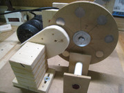
  • Hi all, been working on the project some more today and decided to build another magnet rotor.
    The magnets are inset into the wood, like the first rotor that was built.

    This rotor is made of aspen wood, 8" diameter and 8 neo magnets this time.

    Made this rotor for safety and to be able to place a core/coil on each side of the rotor for better structural balance.

    Also, will make the magnets all north out on one side, to be able to test turions magnet lock neutralizing method at some point.
    Will probably use the same spacer method between rotor magnets, so they attract each other, to lock them in the rotor better.
    peace love light

    Comment


    • Hi all, another project update.
      Ditched the aspen material rotor, apparently it takes better machinery to lathe that type of wood.
      So, went with the original idea.
      Used 1/4" mdf, 3 discs at 8" diameter, with 8 neo magnet holes.

      The middle 1/4" disc is solid, being used as the permanent magnet spacer, to cause the magnets to attract each other.

      Will also place the magnets all same polarity on one side.

      The magnet rotor is being super glued at the moment, with a ton of clamps.

      Was able to lathe it perfectly round and it has virtually no wobble.
      peace love light
      Last edited by SkyWatcher; 06-27-2019, 01:55 AM.

      Comment


      • Sounds like you are honing your skills. The lathe is so good for
        wheels or rotors. One thing, I have one of Dave's rotors here and
        we all know how he talks about putting magnets back to back with
        a spacer in the middle of the rotor layers. This spacer is very thin
        at 1/6" solid plastic. You see at 1/4" the magnets pulling power is
        almost gone, so be careful.

        Great progress keep trying. Glad to here you are going for the
        "ALL NORTH" polarity on one side and "ALL SOUTH" on the other side.

        Also that you are seeing the importance of building the rotor so
        tolerances can be kept to a minimum. You are on your
        way to O.U. production.

        Comment


        • Hi bromikey, thanks for the reply and positive, encouraging words as always.

          Think it will be ok, a clamp was required to fully seat the magnets, could always add a couple dabs of superglue.

          Yes, they are now all same polarity on one side.

          Tested it on the drill press motor and it has virtually no wobble and is running true (balanced) without any balancing weights.

          Should allow for some close tolerances.

          Should explain the method used to build this rotor, as it resulted in a good magnet rotor.
          Used a metal compass and lightly gouged the circle template.
          Drew 8 lines from center punch mark to edge of discs.
          Then used a jig saw (ideally a plunge router, my universal plastic guide is broken) to cut out three 8" diameter discs.
          Then drilled center shaft hole through all discs, with drill guide (ideally drill press).
          Then lathed all three, 1/4" mdf discs, bolted together at shaft hole.
          Now, since the periphery of the discs are all perfectly round, relative the center shaft hole, it was easy to measure down each line 1" and use a metal punch to mark each drill hole accurately.
          Also, draw a reference line across outer edges of all discs clamped together, using permanent marker, so they can be realigned when needed.
          Then with only 2 of the mdf discs clamped together, used a 1" diameter fostner drill bit for each magnet hole, which gives a tight fit.
          Then clamped all 3 discs together again, lining up the reference lines and bolting center shaft lightly snug.
          Then used many clamps around the outside of the rotor and super glued the seems, all around the periphery of the mdf discs and let dry over night.
          Then lightly lathe any excess glue if needed.
          Then insert magnets.
          Done.

          peace love light

          Last edited by SkyWatcher; 06-28-2019, 02:42 AM.

          Comment


          • Hi all, been working on the project today.
            Had to remount the drill press lower to meet the coils.
            She is running pretty sweet, even without a balancing core/coil on other side of rotor.
            Next step, is to wind the prepared 26 strand coil onto the bobbin.
            peace love light

            https://youtu.be/qUQR_VZL66o

            Comment


            • Good progress, thanks for sharing the rotor build, anyone with a few
              tools can make. That is what we want, to show the whole world how
              the average person can prove the entire scientific community wrong.

              Wrong how? In that we as a people have been lied to for generations
              lies coming from the public schools controlled by the people who hate
              the people. We have been told in book form that getting more energy
              out of an electrical device than is put into it.

              This is wrong teaching, like the FAKE NEWS MEDIA did to Tesla, made
              him out to be a crazy person in his old age. All of N. Tesla's marketable
              invention were stolen from him that could make the thieves wealth
              were immediately produced worldwide.

              The rest of his inventions were shelved. Welcome to Tesla's lenz free
              "COILS FOR ELECTROMAGNETS" patent that is only 1 page. The 1 page
              patent is small and easy to ignore.

              Keep at it SkyWatcher what you are going to witness will change many
              minds and you won't stop short like so many other who get what they
              came for and vanish like cowards.

              You built the rotor properly, obviously as smooth as it is, most of that
              rattling noise is the drill press gearbox with a small amount of core
              cogging sound.

              Once the coils with cores are placed on each side it with be much quieter
              at full speed and even better when the opposition magnets are installed.

              All we need is one guy who is willing to follow the steps that Dave
              Bowling has outlined. Piece of cake. You have all the hard part done
              the rotor is one of the most important parts. Rotors must be strong
              and they must be safe, you did that, however plan to have a safety
              cover in the end that can be removed for viewing the setup, then with
              top in place run it for as long as you like.

              Anyone with speed up load load TESLA COILS FOR ELECTROMAGNETS
              can generate power cheaper on the input than conventional means.

              This is lie #1 that coils drawing watts have to slug down the drive
              motor. Lie #2 is that this drive input can not be further reduced to
              a point that it does not change regardless on the number of generator
              coils used. One good way is to use the opposition or magnetic
              neutralization magnets.
              Lie #3 that this is all an illusion unless it is looped or unless the device
              is sent to NASA for verification.

              Think for yourself men are far and few between. Nice job Sky.

              Comment


              • Hi bromikey, thanks for the great reply.

                Yes bromikey, I am aware of most of the deceptions you speak of and then some.
                Will continue to try my best, even though we have such massive cheating in this realm, and I mean, even supernatural hacking and cheating, so the ones you speak of can get their own way.
                Do hope the divine will curtail these interfences into the affairs of humanity, like yesterday.

                So, was working on the project a bit today and decided to work on the magnet to core neutralization method of turion's, before winding the coil.
                It seems to be working, not perfectly yet, though I can see how it probably can be tweaked further to be so.
                Maybe it needs a little more magnet flux, by placing another magnet stacked to the first one and then tweak from there.
                peace love light

                https://youtu.be/tgU_GgweHzs

                Comment


                • That is right and so much less force is needed to turn that rotor.
                  Great choice yes repulsion for the opposing magnets to neutralize
                  the core to magnet attraction that makes for hard start ups as well as
                  having and overall reduction of drive input while running at full speed.

                  This means you need a SET of repulsion magnets for every SET
                  (1 on each side) of coils and their cores.

                  Glad you are experimenting and figuring out things as you go.

                  Oh and I do see the masses are waking up on the FAKE information
                  war that has been waged against them for decades. The internet and
                  all of the ways we connect is showing us that key ideas were being
                  withheld in the past. NO MORE!!

                  Your machine will do nicely. 2 coils could put you over the top. Also
                  having the right circuits coming off of your coils might improve the
                  output depending on what is being powered. That is later.

                  Last edited by BroMikey; 06-30-2019, 08:15 AM.

                  Comment


                  • Test data

                    Originally posted by Turion
                    Sky,

                    They will say you haven’t proved anything unless you show amp draw of the motor with no coil in place. Amp draw of the motor WITH coil in place and amp draw of the motor with magnetic neutralization in place. I have only ever used repulsion on my builds. When one magnet on the rotor has coils on both sides of it in attraction, the rotor magnet directly across the rotor from it has magnets on both sides of it (that are adjustable) in repulsion.

                    You’re going to be able to prove to yourself that everything I have said is true. If you don’t want to prove it to anybody else, DON’T. You did the work. The knowledge you gain of what is possible belongs to you and no one else. If you CHOOSE to share it, you know what to expect from the naysayers.
                    ...
                    Sky,

                    This is right. Take data and prove to yourself. Then share with the rest of us, please. Without actual measured data record it will be difficult for you to analyze the benefits and value of design features.

                    I assume your input to the motor (drill press) is AC. You can use the AC Amperes as input data but I suggest you use a kiil-a-watt meter at the wall plug recording AC volts, amps, and real power (watts) and PF.

                    Suggest doing this:
                    Rotor only.
                    With core.
                    Keep core in place from here on.
                    With neutralizing magnets.
                    With coil, no load, w/o neutralizing.
                    With coil, no load, with neutralizing.
                    Repeat tests with coils having load and then shorted.

                    Of course when you test with the coil, record the output V, I, PF. Scope shots are nice if you have an oscilloscope.

                    The drill press should give a pretty constant RPM but tach measurements are nice, especially if you're looking for AUL.

                    Temperature of the core, magnets and coils are useful data.

                    Nice workmanship on the prototype. Hoping you can get some useful data and decide to share.

                    Regards,

                    bi

                    Comment


                    • Like Turion has said, don't be pushed and don't feed the trolls.
                      Bi is never going to be happy with your results he comes off sounding
                      (for optics) professional in all his leading statements and as I am sure
                      you have become well aware by now is setting you up as a stupid fool.

                      if Bi does this to Turion he will do it to you so like the boss has stated
                      only share when you want to and don't be rushed into it. Scopes are
                      not needed. Power factor is for something else.

                      The goal is simple AMPS in at the drill press motor will remain constant
                      no matter how many coils are added with opposition magnets helping.

                      Even with a single amp reading on the drive motor and a single coil
                      generating below speed up and after slight speed up proves the point.

                      This is where you are and when it slightly speed up and generates
                      you will have your first victory. Bi and the likes are going to say that
                      this victory is a fraud.

                      Of course you know that tread on the scorpions Nice an easy

                      That's all they're good for
                      Last edited by BroMikey; 06-30-2019, 08:34 AM.

                      Comment


                      • peace love light

                        Hi Sky,

                        I have no grudge with you. I encourage experimentation. The only goal I have is true knowledge derived from facts. I see nothing wrong with collection of data. The more; the better. Get what you can and share what you want.

                        Regards,

                        bi

                        Comment


                        • Hi all, Hi bromikey, thanks for the positive reply.
                          Yes, it seems it should burden the motor much less.
                          Think you are right, those that are meant to awake, are and will do so.

                          Hi turion, thanks for replying and the positive, helpful words.
                          I researched the baking soda/super glue method, wow, that method seems to greatly increase strength of bond and drying time.
                          Thanks for sharing that, why I have not known about this glue method until now, is a mystery to me.

                          Went out to the workshop today for a bit, wanted to try and tweak the permanent magnet attraction to core some more and succeeded.
                          Added another one of those 1/8" thick x 1" diameter neo magnets and stacked it to the other one.
                          Had to back it away a little from the rotor and rotate the magnet bar until the sweet spot was found.
                          It now takes even less force to rotate the magnet rotor than before, would say at least 95% of the force normally required to remove the rotor magnet from the core has been neutralized.
                          Think this method is superior to the odd-even, 7 magnet rotor and 8 stator method, as bill muller used.
                          As this is a passive method and requires no extra power input to achieve.
                          peace love light

                          Comment


                          • Originally posted by SkyWatcher View Post
                            Hi all, Hi bromikey, thanks for the positive reply.
                            Yes, it seems it should burden the motor much less.
                            Think you are right, those that are meant to awake, are and will do so.

                            Hi turion, thanks for replying and the positive, helpful words.
                            I researched the baking soda/super glue method, wow, that method seems to greatly increase strength of bond and drying time.
                            Thanks for sharing that, why I have not known about this glue method until now, is a mystery to me.

                            Went out to the workshop today for a bit, wanted to try and tweak the permanent magnet attraction to core some more and succeeded.
                            Added another one of those 1/8" thick x 1" diameter neo magnets and stacked it to the other one.
                            Had to back it away a little from the rotor and rotate the magnet bar until the sweet spot was found.
                            It now takes even less force to rotate the magnet rotor than before, would say at least 95% of the force normally required to remove the rotor magnet from the core has been neutralized.
                            Think this method is superior to the odd-even, 7 magnet rotor and 8 stator method, as bill muller used.
                            As this is a passive method and requires no extra power input to achieve.
                            peace love light
                            Just out of curiosity, if the attraction of the core is offset by the repulsion of the magnet when there is no coil or load, what happens when a coil is in place producing an electrical output which would cause the core to also become repulsive as the magnet enters proximity of the coil? Wouldn't this simply make the input work harder dealing with now 2 repulsive forces?

                            It seems to me that the "speed up under load" occurs because the speed of the rotor, the attraction to the core and the repulsion caused by Lenz are matched or reasonably balanced.

                            Comment


                            • These coils are storage devices that if wound right at the right rpm
                              delay their energy release til TDC which stands for Top Dead Center

                              Some builders refer to these coils as DELAYED LENZ other say LENZ FREE
                              call them whatever name you so chose. The same coil we wind can be
                              made to operate to drag the drive motor down by connecting all of the
                              many strands in parallel. This method is used for the engineering of
                              generator coils today being a cost effective saving of copper wire 5X
                              or greater, weight per current handling.

                              A conventional generator head producing at 2000 watt has a
                              physical dimension of approx 6" X 6" X 6"

                              A generator head like we are building the same 2000 watts requires
                              more space at 12" X 14" X 14" approx.


                              @ Bi https://media.tenor.com/images/2365797dff5e7624ae8332e977d270fc/tenor.gif
                              Last edited by BroMikey; 07-01-2019, 01:06 AM.

                              Comment


                              • Hi all, tomorrow, will hook up the killiwatt meter to the drill press motor and check the full speed wattage draw with just the core in place.
                                Then, will move the neutralization device into position and see what the difference is at full rotor speed.
                                Hi dragon, bromikey explained it.
                                peace love light

                                Comment

                                Working...
                                X