 Tweet
Tweet
Hi all, Hi pot head, thanks for sharing, whoa, be careful man, put a kights armor suit on for that one. 
Hi bromikey, thanks for sharing, I kind of figured it's not a piece of cake, balancing those forces.
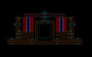
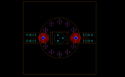
Here is the design I'm going with now, horizontal rotor.
peace love light
Hi bromikey, thanks for sharing, I kind of figured it's not a piece of cake, balancing those forces.
Here is the design I'm going with now, horizontal rotor.
peace love light


Comment