Announcement
Collapse
No announcement yet.
Multifilar Generator Coil - Lenz delay Experiments
Collapse
X
-
Hi all, was busy yesterday, so I didn't explain why I went with this different design.
Firstly, it should be more efficient, mechanically and It is easier to build and less costly to build.
I'm going to get some parts today, to create a motor arbor and extend it also.
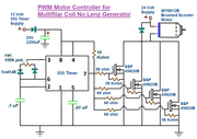
Also, I've been working on a PWM motor contoller circuit, for the MY6812B, will be 4 mosfets in parallel, using 555 timer circuit.
I just want to know that this motor will work in this setup, then I will start working on coil former and other structutral parts.
peace love light
Comment
-
Nice design, the balancing is not so bad just follow the boss heOriginally posted by SkyWatcher View Post
uses a bit smaller magnet, done did deal.
Comment
-
Hi bromikey, thanks for the positive words.
I don't have smaller magnets on hand, though I can always build another rotor later.
I picked up some parts from hardware store to make the motor arbor.
Unfortunately, the threads on the top part of the motor I was hoping to use. are reverse thread, so the nut coupler can't just be threaded on.
So I found a 3/8" coupler that is fairly snug over most of the shaft, so I bored a set screw hole to make contact with flat part on shaft, just need to pick up a tap and die kit to tap the set screw hole.
Was also working on the PWM motor controller circuit, it works well.
Here is the circuit.
peace love light
Comment
-
Yes Sir got to do it eventually get set up with taps and dies plus theOriginally posted by SkyWatcher View PostHi bromikey, thanks for the positive words.
I don't have smaller magnets on hand, though I can always build another rotor later.
I picked up some parts from hardware store to make the motor arbor.
Unfortunately, the threads on the top part of the motor I was hoping to use. are reverse thread, so the nut coupler can't just be threaded on.
So I found a 3/8" coupler that is fairly snug over most of the shaft, so I bored a set screw hole to make contact with flat part on shaft, just need to pick up a tap and die kit to tap the set screw hole.
Was also working on the PWM motor controller circuit, it works well.
Here is the circuit.
peace love light

coupler we all figure out just like you. What I like a lot about you is
your ability to circuit. If you can do it, other can too. Gotcha a pulsed
motor now.
Sweet, see each man has a strength.
 Last edited by BroMikey; 05-16-2019, 08:19 AM.
Comment
-
Remember that the spool thickness where the wire winding goes
around the core material needs to be 1/16" and no greater.
Most of the pvc pipe can be much bigger depending the schedule.
The wood looks great, nice big screws.
SCH40 for 1" is a .133 wall thickness over twice 1\6"
 Last edited by BroMikey; 05-19-2019, 02:53 AM.
Comment
-
Hi bromikey, thanks.
Yes, thought it needed beefier screws.
The pvc pipe is 1/16" wall thickness.
It was an 8 foot length if I remember correctly and came with a metal fitting on the end, It may have been used for hot tubs or something, not sure, got it at menards in plumbing section.
peace love light
Comment
-
Been doin yer homework I see. Some of that is even thinner, perfect.Originally posted by SkyWatcher View Postgot it at menards in plumbing section.
peace love light
I use that stuff myself on occasion when I did the Bedini coils. Good
choice.
Nothing wrong with bushing up of details. For instance my latest coil
"C" core to magnet tolerance using only a 9lb magnet still offers a good
amount of pull with a 1/16" gap. May be 5lbs guessing.
See you next week.
Comment
-
Hi all, back from vacation.
I was doodling in the hotel and came up with a rotor solution I think.
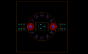
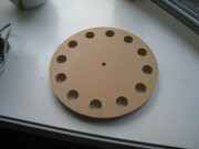
So the rotor will be 3/4" thick and all 12 magnet holes will be drilled clean through.
Then, I thought of using a small disc, using same material as rotor, same diameter as magnet hole and 1/4" thick.
This disc will act as the spacer between magnets, to get them to attract to each other.
Then, some small holes are drilled around the edge of the disc, 1/16" inch deep and out the side of the disc, to accomodate super glue.
The holes will take the glue and not get in the way of the neo magnets that will be placed on each side of the disc.
Will be working on rotor soon.
peace love light
Comment
-
-
You want to know what I do when I drill up holes on my rotors? First IOriginally posted by SkyWatcher View Post
cut the circle and center hole as close as I can. Then I chuck up to a drill
press and turn it to see how far out of round it is and then shave al
little off as needed. That way there is no jumping later, then I lay my
pattern out for the magnet holes.
Sure is a pretty cut you have there, hope she don't jump.
You can still shave a little off and it won't hurt a thing. Make sure you
use the shaft and hub going into the genny. Sometimes I us a bearing
to hold the shaft at the bottom while turning it in the drill press, if it's
really big.
Last edited by BroMikey; 05-25-2019, 02:28 AM.
Comment
-
Hi bromikey, thanks for the positive and helpful reply.
I figured it was more important to spot the holes for the shaft and magnet holes, and the cad print out was used for that.
The roundness of the rotor relative to the shaft hole is probably less critical, though will be done.
Now, if I was placing the magnets in the edge of the rotor, then the method you describe would be best.
peace love light
Comment
-
greetings friends we can communicate by mail to see the cost of shipping, I'm interested in your proposal and thanksOriginally posted by TurionThe machine I recommended (which I have also built and am putting back together at this time) is all N magnets out on the rotor. For EXACTLY the reason Bro Mikey talks about. When you are using a horizontal rotor with magnets on the rotor edge, when a magnet is aligned in attraction with a coil, the magnet directly across from it is aligned with an adjustable magnet on the stator. They cancel each other out. In a vertical rotor, that's magnets on the face of the rotor instead of the edge (so it can have a coil on each side of the rotor) wen the magnet is aligned with the two coils, the magnet opposite it on the rotor is aligned BETWEEN two adjustable magnets that match the face of the magnet aligned to them in repulsion. It will not put out as much as my big machine because it is only 10 coil instead of 12 and does not have as many magnets on the rotor, nor are they as thick. But when I get it back up and running it will STILL prove my point. I know some people are going to whine because it doesn’t put out 2,000 watts, but let them. It is also WAY less expensive to build than my big machine for a number of reasons. Size, number of magnets, etc. So it is THIS machine I have chosen to share for replication.
My BIG machine has N/S magnets on the rotors and 12 coils. But the rotor is larger in diameter by 3 inches and has a second set of magnets out closer to the rim. Each time one of the primary magnets centers between two coils in attraction to both, these secondary magnets center between two magnets on the stator in repulsion. The N side of the magnet is aligned with an N magnet on the stator and the S side of the magnet is aligned with an S magnet on the stator. The stator magnets are adjustable on the big machine just like on the small machine, but I made MISTAKES building the big machine that I corrected when I built the smaller one. The big machine used square magnets that rode in square plastic tubing and the little magnet holder that was adjusted in and out was complex and did not work well. I went to round magnets in pvc pipe for the small machine and that eliminated the magnet holder complexity. Live and learn. It was also CHEAPER, which is always good.
At speed I see no difference in INDIVIDUAL coil output between the two machines, but the number of magnets on the rotor makes a difference as does the thickness of the rotor magnets. One just has more coils and stronger magnets. It USED to have weaker magnets and that is when I compared the output of the coils. Right now, the bigger machine definitely gets MORE out of the coils.
Which brings me to another thought. At SOME point the core is absorbing all the flux it can accept, so the coil will put out NO MORE electricity no matter HOW big or thick the magnets are. I don't know what that point IS.
as a side note: I have an entire box that is probably 18 inches square built out of 1 x 6's holding all of the different rotors I have tried on these machines to get the one I believe outputs the most for the situation. They each have a piece of 3/4 plywood between them so that I can get them apart because the all want to stick together. Some of them are only 1/4 inch thick with a single magnet pressed in, and some have magnets pressed in from both sides. Some are missing some of the magnets because they got pulled out for the NEXT rotor. I would be happy to send ANYONE one of my old rotors so they can experiment if they are willing to pay the cost of shipping up front. I am really tired of people promising me they would pay for shipping and then they get what I sent them for FREE and never paid my shipping costs. I can't tell you HOW many times that has happened, and I don't mind giving stuff away for free or I wouldn't OFFER it, but it is the principal of the thing when people make promises they don't keep.
Comment

Comment