 Tweet
Tweet
Hi bromikey, do you mean to try the device talked about in that thread?
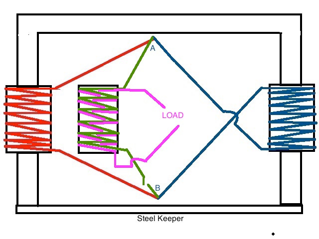
Ok, since you are online at the moment, here is a pic of the setup.
peace love light

Ok, since you are online at the moment, here is a pic of the setup.
peace love light


Comment