Announcement

Collapse
No announcement yet.

My dual monopole SSG and modvid.com

Collapse
X
 
  • Filter
  • Time
  • Show
Clear All
new posts

  • My dual monopole SSG and modvid.com

    Hello all.
    I was just wanting to take this opportunity to thank everyone here who has been providing such useful information for me along my way through my various HHO and bedini energizer projects. I still consider myself an electronics novice at this point and find that i spend alot of time translating what i read before i can proceed forward. Occasionally i take my own intuition and proceed in ways that are likely not correct.

    I'm posting here to receive advice, critique, suggestions, observations etc, with regard to my dual monopole SSG that i just rigged up on a oscilloscope.
    I threw up a simple web page Darcy Klyne's Bedini Monopole Replication to help illustrate where i'm at and what i'm seeing.

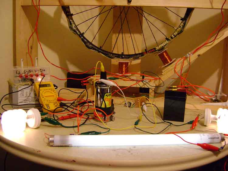
    I have a dual monopole SSG with 5 - 12volt 4.5ah (1 primary, 4 secondaries), 16 ceramic magnets on aluminum rim, set up draws 210ma from primary for both of the bifilar coils (850 windings of #23 and #26) and achieves an average of 180 rps. I've changed the grease in the wheel bearings to a graphite product called Jig-a-loo.

    I am at a point where i am unsure of the best way to charge my battery banks. I have read about using a capacitive discharge on the secondary banks, however i did not see a clear resolution as to exactly why this is necessary. I understand that by putting a battery directly from the secondary position to the primary position that you some how undo the potential charge that has been created by the radiant spikes being delivered to the secondary banks. Is this why a capacitive discharge is used?

    I think Aarron (think that the name. :P) has a good design and will likely order similar Caps to suit his model.

    Seems like research is prudent at every stage of the game from now on in. I am a bit of a electronics novice and appreciate any help from anyone. :P I have built my multi coil design by bridging two separate monopole circuits together and timed them .5 pulses apart from one another. If i were to do similarly and add two more bifilar coils with the same timing will i see a problem? I don't think that this is how a multiple coil circuit has been put together by John himself, but is there anything wrong with doing it this way?

    thanks again everyone.

    ModVid - Watch and Learn TV is a youtube clone that i host to compile a good collection of rare or important video. Please feel free to share your vids there. In the upload section i have set up a youtube downloader. (makes it easy to move video)
    EnergeticTube.com - Where technology goes Live!
    ETaffairs.com - Your Portal Here on Earth

  • #2
    Fixed scope..., I think. :P

    Re-soldered my probes on oscilloscope. I think I have a proper looking H-wave now. I think first few screen shots looked odd. I added new screen shots of what i'm seeing now to the bottom of my page if anyone can advise on that.

    Have seen some oscilloscope screens but can't seem to find any clear ones now that I'm trying to find them. :P

    Also have ordered some MJL21194 transistors to replace my 2n30055 ones that i'm currently using. Hope that its worth upgrading, I've read that there is a big improvement.
    EnergeticTube.com - Where technology goes Live!
    ETaffairs.com - Your Portal Here on Earth

    Comment


    • #3
      tough crowd

      hmmm... tough crowd here.
      Was just hoping for an opinion on what a proper H-wave looked like.
      Last edited by thedude; 08-17-2008, 01:50 AM.
      EnergeticTube.com - Where technology goes Live!
      ETaffairs.com - Your Portal Here on Earth

      Comment


      • #4
        Hi thedude (lebowski I presume? ),

        Can't really comment on your set up as I haven't used the cap set up though your occiloscope shots are interesting as they show something a single coil occiloscope shot doesn't.

        Since no one has said anything yet here are a few of my observations:

        as the voltage induced by the magnets increase you can see there is a slight dip in the rate it is increasing at around the point the opposite coil fires. This shows the slight delay between the transistor turning on and the coil becoming fully energised. The dip is caused by the rotor magnet's attraction to the core after it has passed the center mark and momentarily adds drag on the rotor. Probably not significant but interesting to see.

        also your "blue coil's" flyback voltage isn't dropping as low as your "red coil" because it is staying on longer and so the voltage induced by the magnets increases to a higher level before the coil discharges.

        and the flyback voltage on your red coil is much briefer. Probably because the current is being cut off before the coil is fully energised. This seems like a good thing as less current is being wasted.

        out of curiosity... why have you tuned your coils to fire for different lengths of time?

        I'm afraid I can't view the videos on your site Maybe because I am using Opera.
        "Theory guides. Experiment decides."

        “I do not think there is any thrill that can go through the human heart like that felt by the inventor as he sees some creation of the brain unfolding to success... Such emotions make a man forget food, sleep, friends, love, everything.”
        Nikola Tesla

        Comment


        • #5
          h wave

          TheDude,

          Lee posted a link to a video that will show you the h wave.
          The link is posted in the Bedini SG thread here.
          Sincerely,
          Aaron Murakami

          Books & Videos https://emediapress.com
          Conference http://energyscienceconference.com
          RPX & MWO http://vril.io

          Comment


          • #6
            Originally posted by Aaron View Post
            TheDude,

            Lee posted a link to a video that will show you the h wave.
            The link is posted in the Bedini SG thread here.
            Ahh. that is a very good video of an H-wave. Inductor in a Trigger Circuit

            Sorry for my wine. Although i did get a response. :P Normally wouldn't use such tactics. (I feel shame) I've had trouble discussing these topics with friends and familly and i think i'm developing a bit of a complex.

            Thanks Aaron. Your vids have been very helpful as well.

            Originally posted by Sephiroth View Post
            Hi thedude (lebowski I presume? ),

            Can't really comment on your set up as I haven't used the cap set up though your occiloscope shots are interesting as they show something a single coil occiloscope shot doesn't.

            Since no one has said anything yet here are a few of my observations:

            as the voltage induced by the magnets increase you can see there is a slight dip in the rate it is increasing at around the point the opposite coil fires. This shows the slight delay between the transistor turning on and the coil becoming fully energised. The dip is caused by the rotor magnet's attraction to the core after it has passed the center mark and momentarily adds drag on the rotor. Probably not significant but interesting to see.

            also your "blue coil's" flyback voltage isn't dropping as low as your "red coil" because it is staying on longer and so the voltage induced by the magnets increases to a higher level before the coil discharges.

            and the flyback voltage on your red coil is much briefer. Probably because the current is being cut off before the coil is fully energised. This seems like a good thing as less current is being wasted.

            out of curiosity... why have you tuned your coils to fire for different lengths of time?

            I'm afraid I can't view the videos on your site Maybe because I am using Opera.
            Thanks for the observations. I had looked at some tutorial info on interpreting oscilloscopes, but still could not arrive at exactly what i thought i was seeing. To be honest what has been explained here and as well as the video were not what i had guessed that the wave form was showing. This really has cleared things up for me.

            I haven't set up a capacitive discharge system yet. i have amassed a nice collection of photo flash capacitors though. My experience with caps, ohms, farads is nearly next to nil, but i will say this, I am really enjoying myself with my SSG project and couldn't imagine any better way to experience and learn electronics first hand. I've been having a blast, and i think thats whats missing for me is that i don't have anyone to get excited with. Everyone i associate with is stuck in some sort of dogma that defies change. As well as a capacitive discharge system in the circuit, i can really see the benefit to a battery swapping circuit and I'm investing in that direction as well.

            With regard to the tuning of the coils I had ran tests with a constant supply of voltage and had tuned it by setting the resistance on the trigger with regard to the lowest current draw i could achieve while maintaining the highest RPM i could manage to get. I still haven't put in resistors in place of my pots, although i might add that they were expensive pots and i hope they are relatively consistent. In short i adjusted each coil separately on its own pot to find what felt like a light load with high rpms. (not very solid)

            So if what i'm understanding is correct, would the top of the hump in the h-wave represent an equidistant point between two magnets?

            As far as Modvid.com is concerned i built it on phpmotion 1 just as phpmotion 2 came out. 2 emulates the current version of Youtube more closely, however i can change the plug-in flash player that the script calls to serve the movie on the client side. I'm going to look into a different player. I have Opera running on my laptop with freebsd, so i will definitely do some compatibility tests. Thanks for the heads up. Site hasn't been up for too long so i still have a few bugs to sort.

            Today my MJL21194 transistors arrived so i can swap out my 2n3055's and see what difference there is. I won't get my hopes up too high. :P

            Thanks again guys.
            Last edited by thedude; 04-24-2008, 01:37 AM.
            EnergeticTube.com - Where technology goes Live!
            ETaffairs.com - Your Portal Here on Earth

            Comment


            • #7
              added a video

              I've added a video here (on Modvid.com) or here (on Youtube) of my set up.

              I put in the new mjl21194 transistors and i have seen a distinct difference in the number of pulses per magnet pass in the h-wave.

              I updated my project web page with better images (bought a camera) as well.

              As long as no one minds i'm going to keep documenting here as this seems to be the place where ideas are shared most frequently. I'm not knocking the Monopole group, just haven't gotten much response there. I'm discovering that most of the video content that is relevant to the subject on youtube, came from members here.

              Still having fun and definitely learning.
              EnergeticTube.com - Where technology goes Live!
              ETaffairs.com - Your Portal Here on Earth

              Comment


              • #8
                4 coils now

                I've added 2 more bifilar coils and fiberglassed the wheel. I've updated my project website with a couple more pictures and another new vid just to help others see where i'm at, for better or worse. :P

                My project website

                Soon there will be 8 coils mounted at which point i will really try to balance out my primary load by dialing in the resistance on the trigger side. I still have a bit of trouble understanding how that resistance relates to the current discharged through the power coil. I have noticed that with the 12 volt bulbs removed that my consumption actually went up! Can anyone explain this relationship to me?

                Thanks for your time.
                EnergeticTube.com - Where technology goes Live!
                ETaffairs.com - Your Portal Here on Earth

                Comment


                • #9
                  multiple pulses

                  Originally posted by thedude View Post
                  I've added a video here (on Modvid.com) or here (on Youtube) of my set up.

                  I put in the new mjl21194 transistors and i have seen a distinct difference in the number of pulses per magnet pass in the h-wave.

                  I updated my project web page with better images (bought a camera) as well.

                  As long as no one minds i'm going to keep documenting here as this seems to be the place where ideas are shared most frequently. I'm not knocking the Monopole group, just haven't gotten much response there. I'm discovering that most of the video content that is relevant to the subject on youtube, came from members here.

                  Still having fun and definitely learning.
                  Hey nice setup you made there. I recently built my bedini motor and hooked a scope to it. I noticed when I adjusted the Potentiometer that it would change the number of pulses, and the what would happen is when I had the pot adjusted for minumum resistance the motor would pull the most mA. and it would have the correct H wave form. As I adjusted the pot down the mA would go down and there would be a point were the single pulse would change to multiple pulses and the wheel would slow down. So I would adjust it right before the threshold where the multiple pulses would show up . this would give me the most speed and minimul current usage. that was with a bedini motor setup like you showed the diagram for on your website.

                  Comment


                  • #10
                    Originally posted by vzon17 View Post
                    Hey nice setup you made there. I recently built my bedini motor and hooked a scope to it. I noticed when I adjusted the Potentiometer that it would change the number of pulses, and the what would happen is when I had the pot adjusted for minimum resistance the motor would pull the most mA. and it would have the correct H wave form. As I adjusted the pot down the mA would go down and there would be a point were the single pulse would change to multiple pulses and the wheel would slow down. So I would adjust it right before the threshold where the multiple pulses would show up . this would give me the most speed and minimul current usage. that was with a Bedini motor setup like you showed the diagram for on your website.
                    Hello guys. Nice setup. I am thinking to go multiple coils on my Bedini SSG motor too.

                    For a single coil setup, what I have read about multiple pulses and how it is explained above, is that at the point where they just disappear this is the sweet spot, the point that the system likely runs the best (its COP is the greatest).

                    I do not have a scope so it is hard for me to dial my SSG motor in.

                    From what I understand about the bulb and not using the bulb, from the post above... The bulb is essentially in series with the variable resistor, so it is just there as resistance so you don't go too low on the pot side of the circuit. I don't have a bulb on my motor, I use a 200ohm resistor.

                    There are some explanations here and there how the bedini circuit works. One thing to consider though is that the variable resistor has an effect on the energized coil's discharge rate. From my understanding, the bifillar winding acts as a one to one transformer. So what voltage is produced on one side of the widings it is also produced on the other one and vise versa. Each coil affects one another. By changing the resistance in the pot, there is a consequence to the dI/dt and thus the voltage spike (the rate of change of the current). Also the lower the resistance generally the larger pulse to the transistor base. A larger pulse to the base generally will turn on the transistor more, and the opposite is true with larger resistance on the pot. Not sure if this makes complete sense, I don't want to start to explain the circuit because I have seen some really good explanations that go beyond my understanding. However, in every explanation I have read, they generally fail to mention the 1:1 transformer aspect between the pulse coil and the energized coil, and the effect of the variable resistor.

                    I like your setup. I am investigating how the motor is able to give a battery more charge capacity.

                    Comment


                    • #11
                      Getting a bit better.

                      Heya BinzerBob and vzon17 thanks for your comments. I really enjoy these forums and i appreciate your positive input, as well as not so positive too if need be. :P

                      I took some time to really dial in each coil by using a 1k pot. To get all four functioning so that the wheel would run efficiently at about 200ma, i had a pot on each individual circuit and watched my pulse rate on the scope. For the most part i simply tuned it by ear and checked the draw and rpm. Then I removed each pot individually (careful not to adjust). Using an ohm meter i checked the resistance across the pot itself and replaced the pot in the circuit with a resistor of that value. The pots i used were $15 believe it or not so i thought they would be efficient, however when i dropped in a resistor of that value my rpm increased and my amperage would decrease on the primary than with the pot. In doing that i believe that those circuits are timed for efficiency, not so much rpm. It would seem that the more coils, the more efficient it becomes to run at a fixed rpm.

                      Multiple coils seems to make sense, more radiant spikes i figure.

                      I made some developments on my wheel and added a radiant oscillator like Imhotep's to the mix.

                      Check it out here on Modvid.com or on Youtube.com

                      EnergeticTube.com - Where technology goes Live!
                      ETaffairs.com - Your Portal Here on Earth

                      Comment


                      • #12
                        Making HHO now.

                        Still in a very experimental stage with my set up.

                        The radiant spikes coming out to the secondary banks (ie: HHO electolizer) in the bedini circuit work as others have claimed and have illustrated before this video (latest video of work in progress here).

                        My model is simply an illustration of how one might attempt to create a situation whereby you can dial in a specific resonant frequency in your circuit to enhance HHO production at very low amperage. My observations are that the brown appearance in the water was as a result the use of positve ion flow into the electrolizers, creating oxidization and rust (brown water). This no longer appears to be an issue using radiant vacuum energy in the form of a negative DC Potential (high voltage spikes). My next step is to use the frequencies that Stan Meyer had uncovered to generate a sort of chaotic resonance that i hope will increase fracturization of water into HHO gas. This in addition to a new and hugely more effiecent model (planning on borrowing Jetijs's stacking design) of electrolizer should put this experimental model over the edge toward generating a useable volume of HHO gas.

                        Sorry for so long since my last update. Have moved into my new house and finally have most stressing affairs in my life in good order now.

                        Energetictube.com is my other project that devours my spare time ATM. However during my winter months when i no longer work as a floorlayer i am able to commit to a much more rigorous effort toward developing renewable energy at home.

                        Thanks for reading.
                        EnergeticTube.com - Where technology goes Live!
                        ETaffairs.com - Your Portal Here on Earth

                        Comment

                        Working...
                        X