Announcement

Collapse
No announcement yet.

Free Energy At Last Step By Step Must See

Collapse
X
 
  • Filter
  • Time
  • Show
Clear All
new posts

  • Imhotep,
    Thanks of the help.Probably my battery is sulfated one.I'm not able to make it to retain the charge using a common battery charger.It discharge fast .
    Last night I left your fan charger working on it.In the morning I got full charge,about 6,5V(I'm sorry,but this time I have not monitored the time charging...).But I disappointed when I measured the amps.My digital multimeter started from 6-7 amps and want down after few seconds.Resembled like I was discharging a capacitor.Too fast to read the exact values;however I did not expected such amperage(overcharge?).Now,I dont know how I can go on....

    Comment


    • Originally posted by Philosopher View Post
      Imhotep,
      Thanks of the help.Probably my battery is sulfated one.I'm not able to make it to retain the charge using a common battery charger.It discharge fast .
      Last night I left your fan charger working on it.In the morning I got full charge,about 6,5V(I'm sorry,but this time I have not monitored the time charging...).But I disappointed when I measured the amps.My digital multimeter started from 6-7 amps and want down after few seconds.Resembled like I was discharging a capacitor.Too fast to read the exact values;however I did not expected such amperage(overcharge?).Now,I dont know how I can go on....
      do not be discouraged with quick drain of current . keep draining battery with a 6 volt lamp and repeat process many times to see if you can increase time to drain current
      .
      my 10 amphour 12volt lead acid battery i conditioned raised in capacity over a couple of weeks ! give it a chance to charge -discharge cycles before you evaluate battery.
      “Let the future tell the truth, and evaluate each one according to his work and accomplishments. The present is theirs; the future, for which I have really worked, is mine.”

      Nikola Tesla

      http://www.imhotepslab.com

      Comment


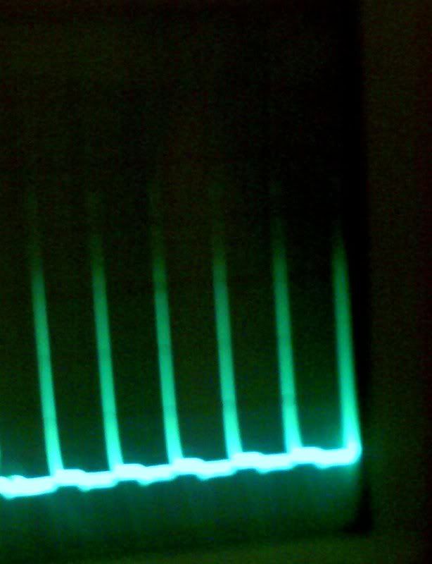
      • Camera doesnt do the oscilloscope justice, but its averaging 250 volts per spike. One of my better fans. Thats the fan i will be using to charge the caps for aarons water spark plug experiment. Yes the fans have many uses. It takes about 4 seconds to charge a 250volt 680 uf cap.
        “Let the future tell the truth, and evaluate each one according to his work and accomplishments. The present is theirs; the future, for which I have really worked, is mine.”

        Nikola Tesla

        http://www.imhotepslab.com

        Comment


        • Hi,

          I'm new around here but very interested in this forum. I have built 2 brute-force Hydroxy generators (using an open-bath series design) but from reading many of the posts I can see that I'll need to use some sort of radiant/resonant design to get more gas production. Now, I'm no EE but I do have a few clues about circuits and the core principle seems to be pulsing a coil with very sharp voltage spikes. The circuits from Meyers onwards all seem to use the 555 timer but the max frequency for those chips is a few MHz. However, while looking at a wikipedia article about diodes
          ( Transient voltage suppression diode - Wikipedia, the free encyclopedia )

          I found this document about Transient Voltage Suppression (TVS) diodes:

          http://www.st.com/stonline/products/...re/an/5628.pdf

          Figure 4.d shows the voltage across a Trisil device and the voltage peaks look really really sharp - Ouch! Since the reaction time of TVS is about 1 ps (1 millionth of 1 microsecond) is there some way of using this behaviour to cause very sharp spikes?

          In the attached picture I have attempted to show my naive placement of 2 extra components. As the Mosfet starts to conduct the voltage across the resistor & TVS diode in parallel will rise. No current flows via the diode until the breakdown voltage is reached. At which point the diode voltage will drop dramatically and the inductor voltage rise dramatically, ie peak at warp speed, hopefully. Would this work?

          Maybe I should just wait until August 1st, hehehe...


          Buccaneer
          Attached Files

          Comment


          • Originally posted by Buccaneer View Post
            In the attached picture I have attempted to show my naive placement of 2 extra components. As the Mosfet starts to conduct the voltage across the resistor & TVS diode in parallel will rise. No current flows via the diode until the breakdown voltage is reached. At which point the diode voltage will drop dramatically and the inductor voltage rise dramatically, ie peak at warp speed, hopefully. Would this work?

            Maybe I should just wait until August 1st, hehehe...

            Buccaneer
            Hi Buccaneer,

            The schematic you have attached shows the same setup from page 7 of the D14.pdf document concerning Dave Lawton's Meyer's Replication. The main difference is that the zener diode isn't shown in the Lawton circuit (but has been discussed on these forums before, including the reason for using it) and the bifilar inductor is connected differently in order to get some reverse current power to flow into the cells. The other addition that I (and others) have made (which has also been discussed on the forums here) is adding a diode before the bifilar path going from the MOSFET to the cell. That's to prevent the reverse current from going back to the FET and actually creates two spikes (one from the FET, the second from the reflection/reverse).

            Good Luck,

            ITF

            Comment


            • Hello All,

              Shiva has been working really hard on getting the site together. We have a special section called a Interactive FAQ and in it we have it separated for each of the projects I have released and will be releasing. For everyone who has built the Imhotep-Bedini fans we would like to see your master pieces! She has created a special section for everyone to show off their work.
              You can go here and post pictures of your fans and circuits. We cant wait to see your fans!
              “Let the future tell the truth, and evaluate each one according to his work and accomplishments. The present is theirs; the future, for which I have really worked, is mine.”

              Nikola Tesla

              http://www.imhotepslab.com

              Comment


              • Many Thanks

                I haven't achieved my ultimate goal of running the shed off the grid.

                But I have achieved control over my own destiny. This is more important than anything else.

                Many many thanks to Imhotep, Shiva and everybody else.

                Attached Files

                Comment


                • First try

                  Hi Imhotep,

                  as so many I have watched in awe radiant energy applications being discussed on this forum for a while now, however that I would get the chance to build one for myself I had no Idea. You made it happen! I bought the components and I started assembling the circuit today

                  I modified the stator, yup I learnt soldering and so far it looks right. I know I have alot of reading to do and I try not to bothre you with unnecessary questions. However I have problems comprehending the circuit when it comes to attaching the batteries. Do you have a blueprint other then the one shown in your 4 part video instructions so I can print it out and study it properly?

                  Anyway, thank you so much for your devotion, you made me trust in my thumbs again

                  my regards to shiva!
                  rvg

                  Comment


                  • Hi Imhotep

                    found your website. And with that the answers to my question!

                    Imhotep's Laboratory FAQ • View topic - Schematics

                    Comment


                    • i did not use ssg's to power the radiant oscillator but the ssg can be used in aarons water spark plug to charge the cap in a few seconds isolated .i have previous commitments and am being stretched thin so i have not been able to complete his experiment yet .also a power correction circuit will emerge for the cf bulbs to get the real power savings as revealed by Dr. Peter Lindemann
                      “Let the future tell the truth, and evaluate each one according to his work and accomplishments. The present is theirs; the future, for which I have really worked, is mine.”

                      Nikola Tesla

                      http://www.imhotepslab.com

                      Comment


                      • Wraps.... totally messed up the wraps. My daughter and I are building one of these together, and I misunderstood the part in the video about the coils. Based on the diagram I found here on this post, I ended up connecting each coil to its own post and disconnecting the adjacent coils. Do I need to go back and re-wrap from scratch or is there any way to reconnect the + and - coils?

                        Comment


                        • without seeing the coil structure its not easy for me to advise on the wraps , but the way most fans were wrapped is as follows =three posts, one post has two wires on it , you separate the one post that had two wires on it and place one of the two wires on an additional post you provide in the 4th post position that is on the stator then solder the second wire back on the original post that had 2 wires originally on it and then check for continuity between the 4 posts and most likely you will end up with two sets of coils ,one for trigger and one for power . if you still have problems you can check out my website and get more detailed instructions at Imhotep's Laboratory | Renewable Energy
                          “Let the future tell the truth, and evaluate each one according to his work and accomplishments. The present is theirs; the future, for which I have really worked, is mine.”

                          Nikola Tesla

                          http://www.imhotepslab.com

                          Comment


                          • power factor correction

                            Imhotep,

                            I'm glad you're working on PF correction. Everyone should get a Kill-a-Watt meter. They'll see very quickly how they're being conned by the industry. We don't pay for what we're told we pay for.
                            Sincerely,
                            Aaron Murakami

                            Books & Videos https://emediapress.com
                            Conference http://energyscienceconference.com
                            RPX & MWO http://vril.io

                            Comment


                            • you are absolutely correct Aaron ,me and Peter worked on his hypothesis and he instructed me on the proper use of the kill-a-watt meter and proved to me what he was talking about. we are being mis informed on the actual billing of our power when it comes to energy saving cf bulbs . they appear to be billing us for approximately twice as much as the advertised wattage on the deceptive packaging . peter has suggested a work around for the discrepancy and i am experimenting with the values we can use to resolve the issue. the meter can be purchased at harbor freight tools for 20 $ and the procedure will be posted on my website Imhotep's Laboratory | Renewable Energy soon . as well as this forum. there are many other units in your home and business that will benefit from this investigative procedure you all owe Dr Peter Lindemann many thanks for his tireless work and unending and infinite wisdom
                              “Let the future tell the truth, and evaluate each one according to his work and accomplishments. The present is theirs; the future, for which I have really worked, is mine.”

                              Nikola Tesla

                              http://www.imhotepslab.com

                              Comment


                              • Originally posted by **~Imhotep~** View Post
                                you are absolutely correct Aaron ,me and Peter worked on his hypothesis and he instructed me on the proper use of the kill-a-watt meter and proved to me what he was talking about. we are being mis informed on the actual billing of our power when it comes to energy saving cf bulbs . they appear to be billing us for approximately twice as much as the advertised wattage on the deceptive packaging . peter has suggested a work around for the discrepancy and i am experimenting with the values we can use to resolve the issue. the meter can be purchased at harbor freight tools for 20 $ and the procedure will be posted on my website Imhotep's Laboratory | Renewable Energy soon . as well as this forum. there are many other units in your home and business that will benefit from this investigative procedure you all owe Dr Peter Lindemann many thanks for his tireless work and unending and infinite wisdom
                                Ok.Now we need a small generator, probably TPU to power all light in house. Brilliant idea !

                                Comment

                                Working...
                                X