It still is coming. I am currently fine tuning and gathering my data for the video for it. I should be releasing it within the next week or so
Announcement
Collapse
No announcement yet.
Free Energy At Last Step By Step Must See
Collapse
X
-
“Let the future tell the truth, and evaluate each one according to his work and accomplishments. The present is theirs; the future, for which I have really worked, is mine.”
Nikola Tesla
http://www.imhotepslab.com
-
Hello and Help : )
Hello Guys,
I've started replicating Imohteps fan SSG. I'm busy sorting out `what goes where` .
I've read through most of this forum to ensure I do this right.
Two questions I have, I hope someone can shed some light on for me.
1. Do I understand correctly that the fan's PCB is eliminated from the design?
Meaning, that its not necessary to use the PCB the fan came with?
2. Is it essential to have a fan with coil to coil resistance of at least 40ohm in order for the fan to spin up with this circuit? Would a larger fan of say 2.5ohm from coil-to-coil work?
Many thanks to all!“If Edison had a needle to find in a haystack, he would proceed at once with the diligence of the bee to examine straw after straw until he found the object of his search.
I was a sorry witness of such doings, knowing that a little theory and calculation would have saved him ninety per cent of his labor.” ~ Nicola Tesla
Comment
-
Originally posted by CitizenDC View PostHello Guys,
I've started replicating Imohteps fan SSG. I'm busy sorting out `what goes where` .
I've read through most of this forum to ensure I do this right.
Two questions I have, I hope someone can shed some light on for me.
1. Do I understand correctly that the fan's PCB is eliminated from the design?
Meaning, that its not necessary to use the PCB the fan came with?
2. Is it essential to have a fan with coil to coil resistance of at least 40ohm in order for the fan to spin up with this circuit? Would a larger fan of say 2.5ohm from coil-to-coil work?
Many thanks to all!
2. Fans have been made for up to 24V.. It does sound reasonable to me that a larger fan would work...
Great videos on Imohteps site... for step by step how to build...
Keep going don't stop!See my experiments here...
http://www.youtube.com/marthale7
You do not have to prove something for it to be true. However, you do have to prove something for others to believe it true.
Comment
-
Hello again.
Has been playing with my setup for a while, have some observations and questions too. Haven't tried to charge any batteries yet, only tested circuit with my multimeter and tried to charge 100 V cap.
Observations:
1) Works with 65V AC neon, and it doesn't get too bright even connected to 20V DC source.
2) Neon glows in way of pulsing, If I calibrate fan for max speed, pulsing frequency goes up, and it looks like it isn't pulsing any more.
3) Yet, the neon is brighter when frequency is lower, and when frequency is lower - current draw is lower to.
4) The fan gives interesting sound, I concluded that it is because of load applied to one side of it. It is a kind of high pitch sound impulse, repeats at the same frequency as the neon lights up. But the pitch goes down as long as fan goes faster. Didn't have time to make video...
5) Max resistance on variable resistor @10V source was ~ 3,09 kOhm, more than that and fan will slowly stop spinning.
6) Measured DC voltage on output, was able to get from ~ 1 - 9 V without load. The highest voltage was when neon light was the brightest. And that was @ 20 V source and relatively low rpm.
7) Accidentally disconnected high-speed diode, yet circuit worked. Couldn't see any difference at all in my current/voltage readings, compared with or without diode. Yet from listening to fan sound I intuitive concluded that circuit will be better without the diode.
8) Tried charging 100V 1000uF cap, it went up to ~ 60 V almost instantaneously. But can't compare to convectional charging, because don't have 60 V DC charging source.
And so - few questions:
1) Is "pulsing" operation common with this set up? As far as I understand, It should be...
2) What function has the high-speed diode in this circuit? I understand, that in one way the current flow must be limited (to create voltage difference between transistor's base and emitter), but that we can accomplish with just severing the circuit in that point. Why we must permit current flow in opposite direction?
3) About 65V AC neon - does it means that my circuit is "weak"? Or it is quite flexible about neon parameters?
So far, looks interesting. Nice thing to play around. Thanks.Energy For Free For Everyone! EFFFE!
Comment
-
Originally posted by theremart View Post1. Yes unsolder it and remove it.
2. Fans have been made for up to 24V.. It does sound reasonable to me that a larger fan would work...
Great videos on Imohteps site... for step by step how to build...
Keep going don't stop!
Thanks ThereMart for the info and push!
Thanks to Imhotep for taking the time to share your research!
I've connected it to a battery and its charging , its being powered by a bench psu for now.
“If Edison had a needle to find in a haystack, he would proceed at once with the diligence of the bee to examine straw after straw until he found the object of his search.
I was a sorry witness of such doings, knowing that a little theory and calculation would have saved him ninety per cent of his labor.” ~ Nicola Tesla
Comment
-
Originally posted by CitizenDC View PostYEAH! Its running!
Thanks ThereMart for the info and push!
Thanks to Imhotep for taking the time to share your research!
I've connected it to a battery and its charging , its being powered by a bench psu for now.
WOOOO HOOOO
It is Christmas feels great to get these going, I am happy for you.See my experiments here...
http://www.youtube.com/marthale7
You do not have to prove something for it to be true. However, you do have to prove something for others to believe it true.
Comment
-
Originally posted by Tehnoman View PostHello again.
And so - few questions:
1) Is "pulsing" operation common with this set up? As far as I understand, It should be...
2) What function has the high-speed diode in this circuit? I understand, that in one way the current flow must be limited (to create voltage difference between transistor's base and emitter), but that we can accomplish with just severing the circuit in that point. Why we must permit current flow in opposite direction?
3) About 65V AC neon - does it means that my circuit is "weak"? Or it is quite flexible about neon parameters?
So far, looks interesting. Nice thing to play around. Thanks.
1. The Bedini circuits often use pulsing to to get max benefit of charging batteries. It does seem reasonable that one could use a 555 timer to discharge the cap being charged with the fan to the battery to get the max benefit out. I have not done this, but interesting idea.
2. I can't answer this someone else may have to fill in... It is modele on the Simple School Girl Circuit, so if you read up on that you will find the answers..
3. I myself like my transistors too much to use the neon to test how good the circuit is performing, I have switched to using a 110V nightlight hooked up as load, the brighter the nightlight the better the charge... ( at least that is my testing method ) there are many other ways to test.
Yes many many options with this circuit.... Thanks to all that contributeSee my experiments here...
http://www.youtube.com/marthale7
You do not have to prove something for it to be true. However, you do have to prove something for others to believe it true.
Comment
-
for the people who want to rewind the fans to their own specs or have damaged the windings this demo will show what is meant by bi filer winding and how to wind the stator
YouTube - Free energy - Bi-Filiar winding for Bedini Imhotep Fan“Let the future tell the truth, and evaluate each one according to his work and accomplishments. The present is theirs; the future, for which I have really worked, is mine.”
Nikola Tesla
http://www.imhotepslab.com
Comment
-
a beginners question re. Bedini circuit with 3 modified PC fans like the one build by
Hi there,
I just finished soldering together my first Bedini circuits and modified several PC-fans the way it was described in the forum and by various videos.
However, I have quite a few questions re. the subject of a Bedini circuit with 3 (or more) modified PC fans.
--Hence, may I ask you a few technical questions?
Some people in the forums have mentioned that the circuit functions better, if a different kind of diode is used accross the transistor (such as the fast switching diode 1N914) or that a different transistor is used altogether (such as MJL21194).--Do you have any suggestions on that subject?
At the momemt I use appr. 6-15V from a laboratory mains adapter for testing the setup with one fan.
--At appr.10V I can see the neon bulb firing (depending on the kind of fan I use.
--Each fan has different characteristics of course, amps, resistance, etc.), so I suppose, the circuit is working ok.
I've tried charging various kinds of batteries (LiIo, NiMh) and they do charge to their specified voltage, although when I discharge them via a light bulb, they lose their charge very quickly (within appr. 10 Min.--However, this is not the case if I have charged the batteries
in the traditional way using a charger).--Any ideas why this is happening with my setup?
From what I've understood so far if you want to use more fans, each fan has to have it's own Bedini circuit.
Do you have any idea (for instance from experimenting yourself or by discussing the subject) how exactly to wire the 3 modified fans in parallel?--Do the fans which you put in parallel have to be exactly of the same rating?
Looking forward to your reply.
Peter (from Germany)
PS
--One more general technical question.--Where in the circuit would you have to put capacitors (like some people have mentioned they did) to improve the setups' functionallity?--Of what voltage
and capacitance rating would they have to be?--Tx
PPS
Here is an explanation of what I accutually want to achieve:
On my walking tours I want to listen to my mp3-player (via headphones while I'm hiking, via 1 watt stereo amp and stereo speakers while in my tent) without ever having to stop in cities in order to re-charge my batteries via a battery charger.
Now, I could carry a bunch of batteries with me (or a charger, as I used to), or a large solar panel, but beside it being heavy, this prospect doesn't fascinate me.
I ultimately like to run my mp3-player (and the 1 watt amp + speakers) via a Bedini circuit with 3 or more modified PC-fans (with their fan blades cut off and assebled in a small PVC-tube for better handling's sake), running and charging sets of LiIo batteries (such as found in handys, appr. 3.7V, 700 - 1500 mA in row in order to achieve 7,4V or 11,1V), perhaps together with a electronic switching system (small IC or transistor circuit) that either by timing or voltage sensing switches between the battery packs in order to keep the setup running indefinitey or at least for a long time.Last edited by peter4you; 08-13-2008, 07:27 PM.
Comment
-
RE: fluffy voltage.
I also have found that I can charge better with a standard charger than using a fan. That or using and SSG with magnets seem to charge better.
The fan does seem to have limitations.
MartSee my experiments here...
http://www.youtube.com/marthale7
You do not have to prove something for it to be true. However, you do have to prove something for others to believe it true.
Comment
-
Originally posted by peter4you View PostHi there,
I just finished soldering together my first Bedini circuits and modified several PC-fans the way it was described in the forum and by various videos.
However, I have quite a few questions re. the subject of a Bedini circuit with 3 (or more) modified PC fans.
--Hence, may I ask you a few technical questions?
Some people in the forums have mentioned that the circuit functions better, if a different kind of diode is used accross the transistor (such as the fast switching diode 1N914) or that a different transistor is used altogether (such as MJL21194).--Do you have any suggestions on that subject?
At the momemt I use appr. 6-15V from a laboratory mains adapter for testing the setup with one fan.
--At appr.10V I can see the neon bulb firing (depending on the kind of fan I use.
--Each fan has different characteristics of course, amps, resistance, etc.), so I suppose, the circuit is working ok.
I've tried charging various kinds of batteries (LiIo, NiMh) and they do charge to their specified voltage, although when I discharge them via a light bulb, they lose their charge very quickly (within appr. 10 Min.--However, this is not the case if I have charged the batteries
in the traditional way using a charger).--Any ideas why this is happening with my setup?
From what I've understood so far if you want to use more fans, each fan has to have it's own Bedini circuit.
Do you have any idea (for instance from experimenting yourself or by discussing the subject) how exactly to wire the 3 modified fans in parallel?--Do the fans which you put in parallel have to be exactly of the same rating?
Looking forward to your reply.
Peter (from Germany)
PS
It is most convenient for me, if you reply directly to the following email address.--However, respond in any way most convenient to you.-.-Tx
peter4you@ewetel.net
--One more general technical question.--Where in the circuit would you have to put capacitors (like some people have mentioned they did) to improve the setups' functionallity?--Of what voltage
and capacitance rating would they have to be?--Tx
PPS
Here is an explanation of what I accutually want to achieve:
On my walking tours I want to listen to my mp3-player (via headphones while I'm hiking, via 1 watt stereo amp and stereo speakers while in my tent) without ever having to stop in cities in order to re-charge my batteries via a battery charger.
Now, I could carry a bunch of batteries with me (or a charger, as I used to), or a large solar panel, but beside it being heavy, this prospect doesn't fascinate me.
I ultimately like to run my mp3-player (and the 1 watt amp + speakers) via a Bedini circuit with 3 or more modified PC-fans (with their fan blades cut off and assebled in a small PVC-tube for better handling's sake), running and charging sets of LiIo batteries (such as found in handys, appr. 3.7V, 700 - 1500 mA in row in order to achieve 7,4V or 11,1V), perhaps together with a electronic switching system (small IC or transistor circuit) that either by timing or voltage sensing switches between the battery packs in order to keep the setup running indefinitey or at least for a long time.
Be watching the website for the release should be up in about a week. Imhotep's Laboratory | Renewable EnergyLast edited by **~Imhotep~**; 08-13-2008, 05:31 PM.“Let the future tell the truth, and evaluate each one according to his work and accomplishments. The present is theirs; the future, for which I have really worked, is mine.”
Nikola Tesla
http://www.imhotepslab.com
Comment
-
charging caps, measuring spikes with scope
Originally posted by **~Imhotep~** View Post
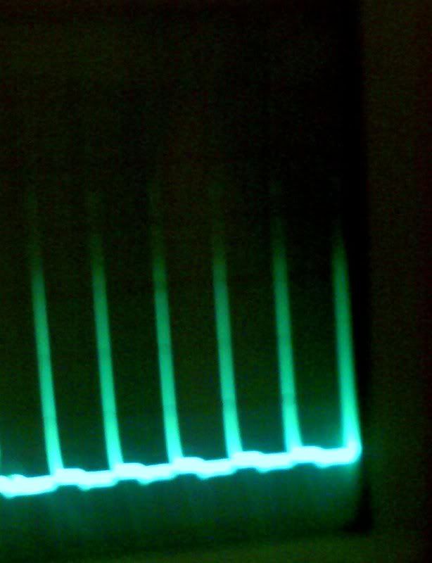
Camera doesnt do the oscilloscope justice, but its averaging 250 volts per spike. One of my better fans. Thats the fan i will be using to charge the caps for aarons water spark plug experiment. Yes the fans have many uses. It takes about 4 seconds to charge a 250volt 680 uf cap.
Tx for swift reply to my 3 fans-question.
I suppose for charging a cap, you would have to place the cap across the charging battery.--Is that correct?
I get a bit confused by the different ratings for caps that can be found in postings on this forum.
Some suggest to use caps with high voltage and low capacitance (600V, 50 uF), others maintain one should use caps with low voltage and high capacitance
(60V, 33.000uF).--Can you explain the different behavior of these two possibillities?--Tx
I have another question re. measuring the spikes with a scope.--Where would you attach the probes of the scope and what would be the basic setting on the scope?
Looking forward to your knowledgeable reply
PeterLast edited by peter4you; 08-13-2008, 07:57 PM.
Comment
-
Originally posted by theremart View PostI also have found that I can charge better with a standard charger than using a fan. That or using and SSG with magnets seem to charge better.
The fan does seem to have limitations.
Mart
I'm testing right now how it works, if I connect a stepup converter between the running battery and the Bedini circuit (either before the circuit or after it.--I will report how it works and if it does anything to improve the setup).
I'm also using a stepup converter when drawing power from the charged battery, when I'm running gadgeds like a mp3 player or a 1W mini stereo amp (with two 3,7V Li-Io batteries in series I get appr. 7,5V of running power that way.--The power supply is more stable and the batteries last longer than without a stepup converter.--I do get appr. 6,5V via the stepup converter just using one 3,7V Li-Io battery, but the battery doen't last long and a mp3 player connented to the battery makes a funny noise.-The stepup converter circuit stays cold and functioning).
Maybe the hints will help.--Keep on fiddlingLast edited by peter4you; 08-14-2008, 02:26 PM.
Comment
-
Ok...
Originally posted by peter4you View PostI've found now that the NiMh batteries don't keep the charge well, but the Li-Io batteries do.--I'm using 2 fans in parallel now, which works well (will try using more fans and experiment with mixed series- and paprallel connections).
I'm testing right now how it works, if I connect a stepup converter between the running battery and the Bedini circuit (either before the circuit or after it.--I will report how it works and if it does anything to improve the setup).
I'm also using a stepup converter when drawing power from the charged battery, when I'm running gadgeds like a mp3 player or a 1W mini stereo amp (with two 3,7V Li-Io batteries in series I get appr. 7,5V of running power that way.--The power supply is more stable and the batteries last longer than without a stepup converter.--I do get appr. 6,5V via the stepup converter just using one 3,7V Li-Io battery, but the battery doen't last long and a mp3 player connented to the battery makes a funny noise.-The stepup converter circuit stays cold and functioning).
Maybe the hints will help.--Keep on fiddling
I also learned from my other experiments I do get a brighter glow of my nite light I use to test if I use a cap on the charging side.See my experiments here...
http://www.youtube.com/marthale7
You do not have to prove something for it to be true. However, you do have to prove something for others to believe it true.
Comment
-
I've been wondering why I've been having such difficulty with my bedini motor. I did a test and it turns out that my transistor is now busted. Don't know when or how I did that one, but I know it was working before.
I was working on rewinding my stator after one of the wires broke, and in the process I broke it again.
Doubt it really matters that I'm only using one coil as the trigger coil, but I'll try again tomorrow to see if I can get it working.
Comment
Comment