Announcement

Collapse
No announcement yet.

Free Energy At Last Step By Step Must See

Collapse
X
 
  • Filter
  • Time
  • Show
Clear All
new posts

  • Check circuit

    Originally posted by cheetoz49r View Post
    when I get the fan running and trying to adjust my potentiameter the fan speed up but my neon light will not turn on. So I connected my voltmeter to the charging end to see what is going on. when I turn the potentiameter when the fan speed up the volt goes up to 2 volts. I already have a diode to the emitter but I haven't try the cap yet I will try that next thank you
    Hi Cheetoz I think first of all check all circuit if you did it right and if the components are good. One have to have long coil for BEMF.
    When neon lights up charge battery should not be connected.
    Comment


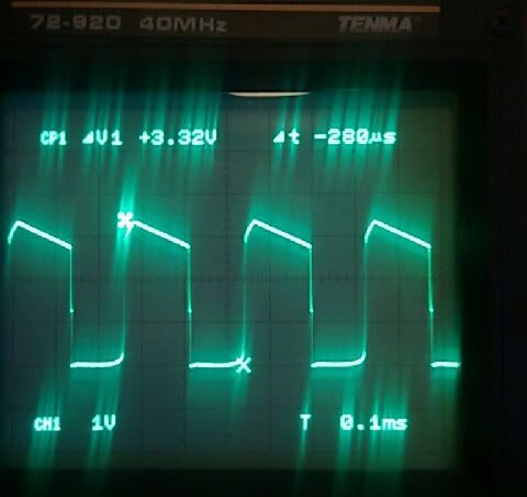
    • Finally I got Oscilloscope to play with bedini desulphator. I've got 2 brushless motors powered up by DC adapter 20v and connected in parallel to 12v 22ah battery. Also both Collectors from the transistors are connected to each other which increases current. It is putting into the battery 33v, 117mah. It is running at 3570hz. Motors are self oscillating (rotors are not turning). Can anyone tell me from the picture, what should I change to improve the results of reviving dead lead acid battery?
      Probes 10x, 1v/DIV, 0.1ms/DIV. The probe is connected directly to collector of the transistor.

      Last edited by Almaz; 04-08-2012, 06:23 AM.

      Comment


      • Amazing Magnet Motor/Gen Rep.

        I thought this would be the best place to post this helpful info. as the thread has already been started with the appropriate title?


        ...enjoy!


        Amazing Magnet Motor/Gen Rep. - YouTube

        Hmmmm?...With magnetic bearings a person my have something...eh?


        I feel so small now!
        Last edited by stargate22; 04-09-2012, 02:17 AM.

        Comment


        • Almaz, revieving dead Batteries is allways some luck, you dont really know if the lead inside in the grid did fall apart or they only are sulfated, What i have read here, most desulfate them with high Spikes and high Frequency. With this Fans are the Limits at the Wiresize as you can see here. American Wire Gauge table and AWG Electrical Current Load Limits with skin depth frequencies
          You can convert them to Alum Batteries too, to make them stronger. They may only have a slight higher self discharge rate, but it should no Problem, because its low, just my need more maintenance charge. Some clean the Plates before they refill it with the new Mix.
          http://www.energeticforum.com/renewa...ies-safer.html


          Stargate, neat Video, just wonder, why this Guy writes at the Description dont waste your Time with rebuild it.
          But may worth a Try, it looks simple enough with for a quick rebuild without expecting any positive Results.
          Theorizer are like High Voltage. A lot hot Air with no Power behind but they are the dead of applied Work and Ideas.

          Comment


          • Originally posted by stargate22 View Post
            I thought this would be the best place to post this helpful info. as the thread has already been started with the appropriate title?


            ...enjoy!


            Amazing Magnet Motor/Gen Rep. - YouTube

            Hmmmm?...With magnetic bearings a person my have something...eh?


            I feel so small now!
            Motore magnetico di Rovella - YouTube
            Half of the Answer is knowing the right Question

            Comment


            • Amazing Magnet Motor/Gen Rep.

              More info......

              The Magnets being used are Microwave rings....best to all in replicating!!

              Yes, they should be in all microwave magnetrons...

              Comment


              • The circuit represented here is nothing more than a high-side boost converter which uses one half of the motor windings as an inductor and the other half as a switching supply to turn on the transistor.

                the initial turn necessary to start the motor will charge the secondary motor windings and the amount of charge stored will be sufficient enough to bias the transistor and force it into saturation, which means the transistor will turn on and starts to conduct.

                Generally this circuit operates in two states. Turn-on and Turn-off states of the transistor which are explained as followings:

                During the turn-on period of the transistor, the primary side of the motor windings, will be short circuited(Connected) across the terminals of the supply battery and it will get charged. At the same time the primary motor windings will induce a voltage into the secondary motor windings by the means of mutual inductance (since they are wounded around the same magnetic core) and force it to change its polarity and the direction of conduction and slowly reduce the supply of current to the base of the transistor. this continues until the primary windings are charged within the allowable time frame. at the same time, the secondary windings will charged as well which this charge will be used to turn on the transistor in the next turn-on cycle.

                During the turn-off period of the transistor, the polarity of the inductor formed by the primary motor windings changes and for a moment the impedance between primary motor windings and the supply battery becomes substantially large (theoretically infinity) until the diode placed between the battery being charged and the primary motor windings(free-wheeling diode) recovers and becomes forward biased and the energy stored in primary windings gets dumped into the battery being charged through the diode.

                The high voltage spikes seen at the output of the circuit is due to the large impedance (theoretically infinity) seen by the inductance of the primary motor windings which indicates the boost capability of the circuit and highly depends on the inductivity of the motor windings and the switching frequency of the transistor.

                But the average power supplied by the primary battery and the average power received by the battery being charged will be the same (neglecting the component losses). By reducing the switching frequency the magnitude of the voltage spikes will increase since it will give more time to the primary voltage windings to charge up; but at the same time it will increase the magnitude of the current supplied by the primary battery which means more energy being supplied by the primary battery and also more being dumped in the charging battery. to achieve this, the resistance between the base of the transistor and the secondary motor windings must be increased in order to reduce the current supplied to the base of the transistor and slow down the process and lower the switching frequency.

                Note: High output voltage spikes do not represent higher output power. any power level can be demonstrated at extremely high voltages. at the end the average power is what that counts which represents the energy being supplied or consumed.

                Also bare in mind that by reducing the switching frequency and increasing the supply current of the primary battery, the average power rating of the components may be excited which will result in component failure. (In other word you may burn or cook the transistor or melt the motor windings and etc.)


                Anyway this is my review of this circuit. personally I do not see any evidence which proves that this system can output an average power grater than its average input.

                if you need switching battery chargers there are tons of better circuits out there to achieve this.

                Instantaneous high voltage spikes (surge) is not recommended for batter charging application, but if you need it, make sure that components with high power ratings are selected.

                Comment


                • Well, the good Thing at this Circuit is, that noone do force YOU, to rebuild it.
                  Most what rebuild the Circuit and ask here, are happy, when they can this one get to working.
                  So, your long Posting at your Reply #1 here is for sure not very helpful for the most.
                  What is your concern, that you do need to post now here?


                  Originally posted by aminsmg View Post


                  But the average power supplied by the primary battery and the average power received by the battery being charged will be the same (neglecting the component losses). By reducing the switching frequency the magnitude of the voltage spikes will increase since it will give more time to the primary voltage windings to charge up; but at the same time it will increase the magnitude of the current supplied by the primary battery which means more energy being supplied by the primary battery and also more being dumped in the charging battery. to achieve this, the resistance between the base of the transistor and the secondary motor windings must be increased in order to reduce the current supplied to the base of the transistor and slow down the process and lower the switching frequency.

                  Anyway this is my review of this circuit. personally I do not see any evidence which proves that this system can output an average power grater than its average input.

                  if you need switching battery chargers there are tons of better circuits out there to achieve this.

                  Instantaneous high voltage spikes (surge) is not recommended for batter charging application, but if you need it, make sure that components with high power ratings are selected.
                  By reducing the switching frequency the magnitude of the voltage spikes will increase since it will give more time to the primary voltage windings to charge up;

                  Thats not what i have seen on this Fans.
                  The Spikes always stay approximatly the same, the height of the Spikes depends on the Windings, not 'Time to charge up the primary voltage windings'.

                  to achieve this, the resistance between the base of the transistor and the secondary motor windings must be increased in order to reduce the current supplied to the base of the transistor and slow down the process and lower the switching frequency.

                  INcreasing the resistance at the Base from the Transistor here allways cause a speeding up from the Fan, not reducing from the Frequency.

                  Basically. Lower Resistance at the Base only cause a lower Resistance at the Transistor,
                  therefor, it switches more Current.

                  This Project is actually only a starter Project. The Input/output Rate measured is indeed negative. The Effect is somewhere else.

                  But since you dont bother with this Project further, better stay by your 'Tons of better Circuits' and dont think further about this, happy boiling your Accumulators, because this one stay cold.
                  Even when you charge up normal Batteries or (carefully) button Cells, what is, of course, for YOU impossible, because maybe only 'Refresher' could charge them up a limited Time.
                  Theorizer are like High Voltage. A lot hot Air with no Power behind but they are the dead of applied Work and Ideas.

                  Comment


                  • I see similar circuits using just coils and forcing frequency into transistor/fet but do we get radiant negative energy with that setup without using magnet?

                    Comment


                    • Almaz theoretically you could, depends on the Circuit, what you mean, there are a lot possibilities for a Circuit. But the Magnets are mainly here to trigger the Transistor, not that they really create additional Energy. Thats actually a Yes/No Point.
                      Some said, her Joule thief circuit works great with some modification as desulfator, other said, Circuits from the Web are the best. I think it depends more on the Batteries, the Amount and the Frequency, how well a Circuit as Desulfator works.
                      Which one is right, you may only know, when you rebuild it, and have the same Batteries.
                      But one thing for sure, when you charge the Batteries in this way like here, they stay more healthy and become more Capacity as with the classical teached Way.
                      Theorizer are like High Voltage. A lot hot Air with no Power behind but they are the dead of applied Work and Ideas.

                      Comment


                      • hehe, everyone misses the point as usual.

                        This is a learning tool and these are the facts you need to think about.

                        Almost 100% of the energy put into this device is shorted on the source.

                        It is a 1 to 1 transformer but the output voltage is over 10 times the input.

                        The output current is negligible.

                        Almost nothing, in terms of watts is charging the battery at a more efficient rate than if the batteries were joined directly together.

                        Charge efficiency is almost 1 to 1 when the batteries are sized correctly. I achieved 97% + or _ 3%

                        It improves the condition of the battery being charged.

                        The fan is running and when this energy is added to what is found in the charging battery, the sum of the 2 is greater than the supply.

                        What I get from this, is that something anomalous is happening in terms of how the battery is being charged and as all the input power can be accounted for in terms of losses and what is returned to the source, what is powering the motor? It must be said that this is true of most motors.

                        This motor needs to be seriously studied at the major universities to explain what is happening but of course they wont do it and they can't explain it.

                        Build it, test it and learn from it as 1000s already have

                        Comment


                        • Hi mbrownn!

                          Very Well Done for your clear analysis

                          As per what is going on on many coils experiments, I'm more and more convince of a conjecture I made of the existence of a kind of "ElectroMagnetic-Ventury Effect": a "primary flow of energy", capture the environment energy, like the flux of water molecules captures the molecules of air and add to them. But in EM energy, primary and secondary energy would be same nature. And the overunity COP is obtained by this adding environmental free energy.

                          Cheer, Khwartz.
                          Trying to understand perfectly something, observing by one's self to check the truth, is the only way to skills and to protect oneself from false data and rumors.

                          Comment


                          • Originally posted by Khwartz View Post
                            Hi mbrownn!

                            Very Well Done for your clear analysis

                            As per what is going on on many coils experiments, I'm more and more convince of a conjecture I made of the existence of a kind of "ElectroMagnetic-Ventury Effect": a "primary flow of energy", capture the environment energy, like the flux of water molecules captures the molecules of air and add to them. But in EM energy, primary and secondary energy would be same nature. And the overunity COP is obtained by this adding environmental free energy.

                            Cheer, Khwartz.
                            Many talk about this vortex and it may well be a fact although I do not know how to prove it. I do like your analogy. The energy does not appear to be the same as our "normal" electricity as there is little or no amps. I cannot see how we are putting it in so you are right, it must be coming from the environment.

                            Comment


                            • Sorry, wrong topic
                              Last edited by Marcel-o; 04-20-2012, 06:00 AM.

                              Comment


                              • Originally posted by mbrownn View Post
                                Many talk about this vortex and it may well be a fact although I do not know how to prove it.
                                Could be we should find this in academic physics too, could be around the Feynman's concept of "vector-potential".

                                I do like your analogy.


                                The energy does not appear to be the same as our "normal" electricity as there is little or no amps.
                                If high voltage, looks to me quiet normal to have very little amps! for same wattage...

                                Would be interesting so to calculate the ratios to compare in terms of Watts. But needs to be done with True-RMS meters! but You told me, if I remember well, that measurements changes itself the values; right? :/

                                But to be "unnormal", I'm not sure for this evaluation. EM does exist in molecules and atoms. I'd be very curious to do same experiment in vacuum, to know if comes from air-molecules or directly form the (Dirac's) "plenum".

                                I cannot see how we are putting it in so you are right, it must be coming from the environment.
                                As electricity has much to do with waves, and as waves behaviour can produce kind of attractions, and that could be any flow of energy has a tendency to set the environment to follow the same path (the very venturi-effect), I would not be surprised that if the aether does exist, it would have same effect with high voltage than with high pressure (while, and it's very interesting for me: both are mathematically equivalent in physics equation in terms of behaviour). Hight pressure => hight particles or waves speed => venturi effect.
                                Trying to understand perfectly something, observing by one's self to check the truth, is the only way to skills and to protect oneself from false data and rumors.

                                Comment

                                Working...
                                X