Announcement

Collapse
No announcement yet.

Free Energy At Last Step By Step Must See

Collapse
X
 
  • Filter
  • Time
  • Show
Clear All
new posts

  • #76
    Hello All

    Hi All
    Im new here been reading and building the fan sg Thanks Imhotep (cant beleive your a rush fan thats so cool)
    Its really make life alot easy had no-end of trouble with the north pole motor still useing a reedswitch to get it going.
    Anyway I have a question or two.
    Do i just put a cap in line before the battery to Charge or can i just go into the battery?
    also would love to pulse charge the batterly with a 555 but im not big on eletroics can someone help me out?

    Free energy for All + Freedom=Result

    Comment


    • #77
      Originally posted by Bodkins View Post
      Hi All
      Im new here been reading and building the fan sg Thanks Imhotep (cant beleive your a rush fan thats so cool)
      Its really make life alot easy had no-end of trouble with the north pole motor still useing a reedswitch to get it going.
      Anyway I have a question or two.
      Do i just put a cap in line before the battery to Charge or can i just go into the battery?
      also would love to pulse charge the batterly with a 555 but im not big on eletroics can someone help me out?

      Free energy for All + Freedom=Result
      you can hookup caps directly (it charges them fast be careful) i used large 680 microfarad 250 volt, three fans in parallel output,or one doesn't matter.

      you can also hookup batteries directly of any voltage size, i have mixed different voltage batteries with no problem , monitor volts and be careful.

      as far as pulse charge have not tried ,but have been working on different pulse charger (very interesting arrangement will disclose shortly ,runs 110 or higher resistive loads directly ,all mech. no chips or transistor,not complete on secondary side of tube yet.

      others in forum have 555 pulse project complete with computer fan i did not see schematic details should be further back in thread tho. happy experimenting
      Last edited by **~Imhotep~**; 05-29-2008, 04:58 AM. Reason: addition
      “Let the future tell the truth, and evaluate each one according to his work and accomplishments. The present is theirs; the future, for which I have really worked, is mine.”

      Nikola Tesla

      http://www.imhotepslab.com

      Comment


      • #78
        never give up

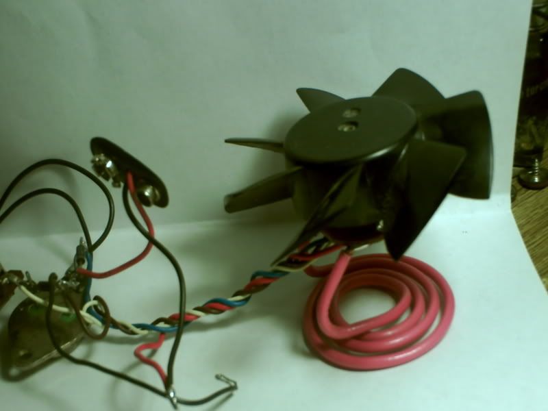
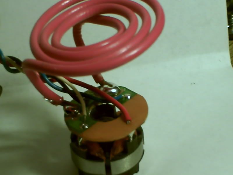
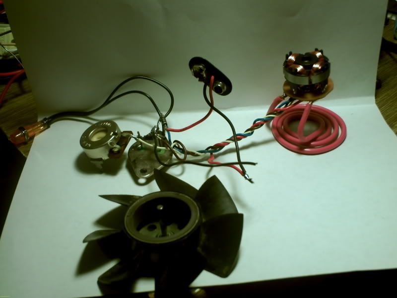
        I noticed that alot of people when they first start building these fans ran into the same problem that i did at first. The casings on some of these fans are a little flimsy and even if your super careful they can easily be broken. That does not mean that the fan is useless. I am posting some pics of one of the fans that i had to take a little imagination with after i broke the outside casing.

        You will take notice of the "tesla pancake coil" i made out of this house wire that holds the unit up. It walks a little bit but it still gives good data.

        A old 2 liter bottle cut into a ring makes a good "protective shroud" to make sure no one can accidentally get hurt when its running.


        it just shows that even with no shroud these little motors can still pack a punch
        “Let the future tell the truth, and evaluate each one according to his work and accomplishments. The present is theirs; the future, for which I have really worked, is mine.”

        Nikola Tesla

        http://www.imhotepslab.com

        Comment


        • #79
          Spikes question

          Hello family,

          I’m planning to do a fan SG and questions arrise.
          Mart says that he had obtained spikes of back emf of 60V and for this reason I’ll need a neon bulb of 120V. So I don’t understand why the secondary battery of 12 V will be able to hold this back emf without burn. Another question is where did you find this spikes, I mean where did you put your osciloscope terminals.
          Could I use a capacitor instead of a neon bulb and for moments of back emf charge the capacitors, and the other times put the energy store in it into the battery?
          Is ok that I use a potenciometer of 1K of range?

          Love to everyone! Thanks for this page!
          Dancing the dance of Shiva in the middle of a meleé of particles, that is to say in the vacuum

          Comment


          • #80
            Protecting your transistor...

            Originally posted by Pcurrius View Post
            Hello family,

            I’m planning to do a fan SG and questions arrise.
            Mart says that he had obtained spikes of back emf of 60V and for this reason I’ll need a neon bulb of 120V. So I don’t understand why the secondary battery of 12 V will be able to hold this back emf without burn. Another question is where did you find this spikes, I mean where did you put your osciloscope terminals.
            Could I use a capacitor instead of a neon bulb and for moments of back emf charge the capacitors, and the other times put the energy store in it into the battery?
            Is ok that I use a potenciometer of 1K of range?

            Love to everyone! Thanks for this page!
            Hi,

            Welcome to the group.

            You are asking the same questions that we have, and are asking... Which is great.

            From my probe I put one on the case of the transistor, and the ground to the primary battery negative. Yesterday I hooked up my ssg with the fan with the fins cut off with a supply of 13V I was getting over 100V spikes, very faint on my scope but were there.

            A good place to start with this project is to look at the datasheet of the transistor you intend to use. Found out the max voltage the transistor can take. ( I often do this the hard way ) But a good rule of thumb is to combine all the voltages going to the transistor and total them up, so if you are charging 12V to 12V you have 24V on transistor approx...

            For your transistor, protection you can try different things as I have but realize replacing transistors can get expensive.

            I use a 1K pot myself, and I think there is good reason to use a lower ohm pot with a 2W capacity, once you find the sweet spot with the 1K, put in a resistor and a smaller pot because it makes it much easier to tune.

            I suggest you check out the ways people have used capacitors on youtube with the SSG, and look at the schematics here, some very good ways to learn is to look at what others have done.

            Peace
            See my experiments here...
            http://www.youtube.com/marthale7

            You do not have to prove something for it to be true. However, you do have to prove something for others to believe it true.

            Comment


            • #81
              Originally posted by Pcurrius View Post
              Hello family,

              I’m planning to do a fan SG and questions arrise.
              Mart says that he had obtained spikes of back emf of 60V and for this reason I’ll need a neon bulb of 120V. So I don’t understand why the secondary battery of 12 V will be able to hold this back emf without burn. Another question is where did you find this spikes, I mean where did you put your osciloscope terminals.
              Could I use a capacitor instead of a neon bulb and for moments of back emf charge the capacitors, and the other times put the energy store in it into the battery?
              Is ok that I use a potenciometer of 1K of range?

              Love to everyone! Thanks for this page!
              the reason that i have found that the charge battery doesn't burn is because this process is a cold charge.
              what i mean by cold charge is conventional charge, pumps larger current charge into the battery it heats up the battery ,this unit puts high voltage
              low current so it is cold .
              it appears that the batteries absorb the high voltage spikes easily and still charges up . hope this helps

              i always monitor the voltage on the charge battery with a very expensive true rms volt meter to be safe it shows voltage spikes numericly without use of scope, the scope gives a better visual display of the spikes (thank you
              themart ) you can use any meter to see some voltage tho.
              happy experimening
              “Let the future tell the truth, and evaluate each one according to his work and accomplishments. The present is theirs; the future, for which I have really worked, is mine.”

              Nikola Tesla

              http://www.imhotepslab.com

              Comment


              • #82
                another one ^^

                Thanks for your answer! Both help me. Then of read what Mart wrote I was thinking about the spikes and I though what you answer, Imhotep, it was because of the cold electricity like Tesla called it. Despite of accomplish the execution of the circuit, before I would like to understand what is going on in it. So I would know what is causing this back emf. I know that is the coil with the help of the magnets that give us the spikes but I don’t really know how. What I think I understand is that when a magnet is spinning and going throw the coil first induces a current that goes to the base and active our transistor and let current flow to the negative terminal of our battery. Then I don’t know why in the other pair of coils is induced our spikes that we see in the battery. I would be pleased if anyone can help me with this.
                Dancing the dance of Shiva in the middle of a meleé of particles, that is to say in the vacuum

                Comment


                • #83
                  Originally posted by Pcurrius View Post
                  Thanks for your answer! Both help me. Then of read what Mart wrote I was thinking about the spikes and I though what you answer, Imhotep, it was because of the cold electricity like Tesla called it. Despite of accomplish the execution of the circuit, before I would like to understand what is going on in it. So I would know what is causing this back emf. I know that is the coil with the help of the magnets that give us the spikes but I don’t really know how. What I think I understand is that when a magnet is spinning and going throw the coil first induces a current that goes to the base and active our transistor and let current flow to the negative terminal of our battery. Then I don’t know why in the other pair of coils is induced our spikes that we see in the battery. I would be pleased if anyone can help me with this.
                  if you look at all electronic circuits with coils there will be a MOV ( metal oxide varistor )on ac circuits and a diode on dc circuits this is a protection device that prevents the coil colapse from damaging the source supply or driver circuits .
                  that is a well documented fact .
                  what the master bendini has done is tame that back rush and divert it for a productive use .
                  what i have done is adapt that effect with off the shelf products that anyone can get easily to see this effect and or use for all our benifit.
                  the nuts and bolts of the process is being analized by every one so please as you build and test share your findings with all of us .
                  the back emf is explained in a great dvd called motor secrets by DR lindemann .
                  happy experimenting
                  “Let the future tell the truth, and evaluate each one according to his work and accomplishments. The present is theirs; the future, for which I have really worked, is mine.”

                  Nikola Tesla

                  http://www.imhotepslab.com

                  Comment


                  • #84
                    Originally posted by **~Imhotep~** View Post
                    you can hookup caps directly (it charges them fast be careful) i used large 680 microfarad 250 volt, three fans in parallel output,or one doesn't matter.

                    you can also hookup batteries directly of any voltage size, i have mixed different voltage batteries with no problem , monitor volts and be careful.

                    as far as pulse charge have not tried ,but have been working on different pulse charger (very interesting arrangement will disclose shortly ,runs 110 or higher resistive loads directly ,all mech. no chips or transistor,not complete on secondary side of tube yet.

                    others in forum have 555 pulse project complete with computer fan i did not see schematic details should be further back in thread tho. happy experimenting
                    Are you looking at somthing on the lines of a tesla switch?
                    Three motor and three relay switchs swapping batterys.
                    I think that if someone could swap the battery after ever cycle it would end up with great results just with a standed bedini setup!
                    Go one step on form that and parallel and serial the batterys.
                    Would this workk? Im new to this so someone may have try it already.
                    Getting great result form the Fan using 9v into 200v cap than on to another 9v charging nicely.
                    will set up a bigger one next week with my oscilloscope and see what going on in there.(where do i conect it? just got it)
                    also got a rf meter coming will that read anythin?

                    Take Care
                    Bodkins
                    Lets Make it Happen Folks

                    Comment


                    • #85
                      Originally posted by Bodkins View Post
                      Are you looking at somthing on the lines of a tesla switch?
                      Three motor and three relay switchs swapping batterys.
                      I think that if someone could swap the battery after ever cycle it would end up with great results just with a standed bedini setup!
                      Go one step on form that and parallel and serial the batterys.
                      Would this workk? Im new to this so someone may have try it already.
                      Getting great result form the Fan using 9v into 200v cap than on to another 9v charging nicely.
                      will set up a bigger one next week with my oscilloscope and see what going on in there.(where do i conect it? just got it)
                      also got a rf meter coming will that read anythin?

                      Take Care
                      Bodkins
                      Lets Make it Happen Folks
                      all of my testing on de-sulfation of larger batts has been done with a power supply var 0-36 volts. i am evaluating circuit for expansion and have had good results and im sure with a little work this could possibly do battery swapping .if you get good results on battery swapping please share result with everyone in forum. this forum has a great amount of very talented members who helped me. and have shared their results.
                      my projects main focus is to help verify bendini's work and it appears he was absolutely correct in his research so far
                      .i have also ran unit on 9 volt battery worked good . when i first took a throw away 9 volt carbon zinc battery that was not able to run anything and you are not suppose to be able to charge and it took a charge nicely and was useful i was convinced i would test this circuit more.

                      i have not tried running through cap then battery ,that is interesting, did you monitor the caps charge voltage or monitor the battery source and charge battery voltage ?
                      i have ran off pwr supp at 12volt and charged 3- 9v batteries (batteries in series which came to 27 volts output and they charged good ) the output seems to mirror the volts they are discharged down to ,then voltage goes higher as they charge ,i let them go over their combined voltage by a few volts then i disconnect and test their capacity which is good .
                      i have charged batteries in parallel and parallel -series combo all charged good
                      once charged real old carbon zinc that was all leaky and it would not improve
                      but i did not expect it to but tried any way.

                      themart (other forum member -great guy)has hooked up scope between charge battery ground and collector of transistor and monitored spikes. looked great. he said they were over 100 volts.
                      rf meter will be interesting ,please share result

                      happy experimenting
                      Last edited by **~Imhotep~**; 05-30-2008, 03:27 AM. Reason: spelling
                      “Let the future tell the truth, and evaluate each one according to his work and accomplishments. The present is theirs; the future, for which I have really worked, is mine.”

                      Nikola Tesla

                      http://www.imhotepslab.com

                      Comment


                      • #86
                        Been charging one cap on to 9v.
                        the 9v started at 7.89v rose to 8.05v.
                        the cap had 30volt in it all the time.
                        the thing is i stop the charging when i check the primary battery which red somethin like 4.70.
                        I just tuck the primary off and left the charging on and check it after 5mins 8.07v the cap has 27v in it.
                        tryed charging two 200v 470uf they never got over 35v in each.
                        playing is with this stuff is fun

                        Comment


                        • #87
                          I have experienced different voltages with different fans, when i did the cap discharge experiment i had 3 fans paralleled and i was using 13 volts as the source. and it was a 13volt power supply. it rose over 120 volts and i stopped it and then discharged it through 2 10awg house wires.
                          And i did that strictly for effect to show that these can get up to dangerous voltages and for everyone to please be careful. Have fun experimenting
                          “Let the future tell the truth, and evaluate each one according to his work and accomplishments. The present is theirs; the future, for which I have really worked, is mine.”

                          Nikola Tesla

                          http://www.imhotepslab.com

                          Comment


                          • #88
                            YouTube - Bedini computer fan cap pulser with 10 watt globe on the output
                            "Once you've come to the conclusion that what what you know already is all you need to know, then you have a degree in disinterest." - John Dobson

                            Comment


                            • #89
                              Originally posted by ren View Post
                              YouTube - Bedini computer fan cap pulser with 10 watt globe on the output

                              EXCELLENT!!

                              Its takes another step forward. Please share details. 10 watts!!! yay!! great start!!!

                              we are working on the same thing mechanically without the fan tho. We havent released any information with it because we arent done with it yet. We are upping the voltage, we are running 110 volts pulsed, simliar to E.V grays mechanical low voltage side. yay!
                              it is a replication of mallorys vibrator with step up transformers, no electronics, we put a cap 5uf in series with load and it smoothed out the pulses so the light was continous. it was 250 volt. im still working on the video now for youtube. This is exciting to see how fast it is growing.
                              Last edited by **~Imhotep~**; 05-30-2008, 07:43 AM. Reason: spelling
                              “Let the future tell the truth, and evaluate each one according to his work and accomplishments. The present is theirs; the future, for which I have really worked, is mine.”

                              Nikola Tesla

                              http://www.imhotepslab.com

                              Comment


                              • #90
                                The cap pulser is John Bedinis Capacitive discharge circuit for the monopole motor. There are various schematics, but I am hesistant to post due to copyright infringements. You can see one here

                                Bedini_Monopole : John Bedini's Monopole

                                I have a flash capacitor from a disposable camera, 150k instead of 51k on the 555 and a different transistor on the front and back. Theres also a fixed voltage regulator to automatically step down the voltage for the 555 if its higher than 18 volts and an extra cap in there. It lights up a 12 volt 300ma globe constantly without pulsing, only when the load gets larger does it pulse. Charges batteries on the back end quite quickly, and they are more suited for swapping to the front end too when charged this way. The 10 watt globe is just there to show how the back end is pulsed into the battery.

                                High voltage is the way to go Imhotep, the standard sg circuit if built with mlj21194's should be able to handle well in excess of 100 volts input if you have nice thick connections. Have a look at the 24 volt battery swapper thread just below this one, I get heaps more speed out of that when voltage is doubled. That trifilar coil will light up the 10 watt globe on the back end with 12 volt input, unlike the fan.
                                "Once you've come to the conclusion that what what you know already is all you need to know, then you have a degree in disinterest." - John Dobson

                                Comment

                                Working...
                                X