Announcement

Collapse
No announcement yet.

Free Energy At Last Step By Step Must See

Collapse
X
 
  • Filter
  • Time
  • Show
Clear All
new posts

  • Originally posted by **~Imhotep~** View Post
    elcman, check out the free energyfreebe i just posted. A nice little gadget to play with, with your fan.
    Hehehe, nice!

    I've already signed up for Google Checkout so I don't get the same discount, but I think I might have an equivalent solution myself. I found at Radio Shack that they have the barrel car plugs for DC connections. I'm going to hard wire one of those and hook it up to an inverter I bought a while ago to power a radio from my car.

    That thing is just sitting there since I gave that up, so it isn't doing me much good ... until now.

    I might be able to run do some fancy stuff in my "powerless" garage.

    Thanks for the thought, though!

    Comment


    • Originally posted by Rayaz View Post
      Just wanted to share a bit of info I found in the overunity forums for you Imhotep and others researching this.


      Quote from post of someone who produced a larger Bedini device from this thread: Bedini replication in Germany
      That's my next project! I was starting to balk at the idea with the electronics I would have to purchase and put together, but ... this! This is exactly what I needed!

      I'm going to try pulling together some resources for the WFC and put it together with Imhotep's Bendini fan. Someone'll be famous yet!

      Soon these threads will have to merge. So many things apply across...

      One thing I found int he PESWiki that intrigued me and falls in line with that quote...
      Originally posted by PESWiki
      Upon investigation, it became apparent that the switched potential function of the device, in which Voltage translates instantaneously, but the flow of Current is slower to propagate, and is interrupted by the Switch before a closed circuit is actually in effect, is the single mechanism common to all legitimate FE/OU electromagnetic devices, of every description, from Coler (1945) to Stoern (2007) - including the Water Fuel Cell - and likely many prior to that as well.
      Found on the PESWiki
      Pretty fantastic this same switching method really does lie at the root of all of these designs in one way or another. The fan itself is the switch allowing the switching to happen on a larger level without relying (too much) on more fragile electronics.

      Originally posted by Dr. Lindemann
      ... The electronic devices in most instances could not limit or tolerate high power. Finally, it became apparent that the electrical systems, with this type of current limiting requirement necessitated electrical power supplies--not electronic.
      Found on the PESWiki
      Very interesting read. I wish I was a scientific virtuoso... It'd really help me be more of a participant than an observer.

      Comment


      • Originally posted by **~Imhotep~** View Post

        happy experimenting
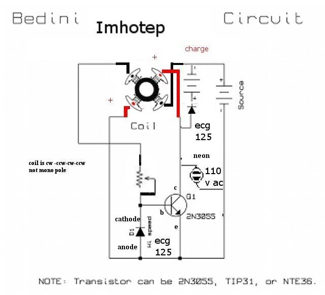
        Hi, you could design a magnified detail of the connections of the coils? Thanks

        Comment


        • Originally posted by riccardom70 View Post
          Hi, you could design a magnified detail of the connections of the coils? Thanks
          great idea will be posting more detailed schematic very soon with magnified pix of coils,i have been side tracked on ev gray replication and discovered something very interesting about his patent, shocked(surprised) me i am working 24/7 on both imhotep fan and ev gray, will get fine detailed schematic up tomorrow 6/4/08 and later disclose ev gray in new thread soon.
          happy experimenting
          “Let the future tell the truth, and evaluate each one according to his work and accomplishments. The present is theirs; the future, for which I have really worked, is mine.”

          Nikola Tesla

          http://www.imhotepslab.com

          Comment


          • more detailed schematics and magnified stator.


            “Let the future tell the truth, and evaluate each one according to his work and accomplishments. The present is theirs; the future, for which I have really worked, is mine.”

            Nikola Tesla

            http://www.imhotepslab.com

            Comment


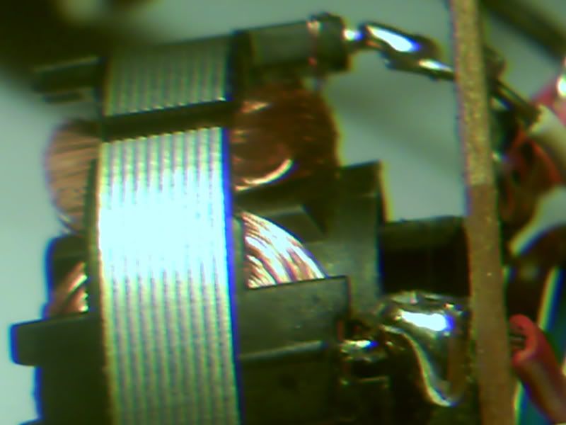
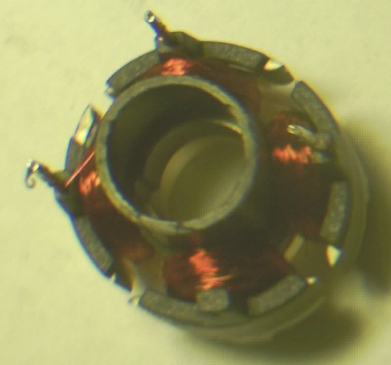
            • these are enlarged pictures of coil winding positions.


              “Let the future tell the truth, and evaluate each one according to his work and accomplishments. The present is theirs; the future, for which I have really worked, is mine.”

              Nikola Tesla

              http://www.imhotepslab.com

              Comment


              • Originally posted by **~Imhotep~** View Post
                more detailed schematics and magnified stator.


                Many thanks


                Ciao from Italy

                Comment


                • hope your good to go, trying to make this as easy as i can for everyone to replicate this quickly. today i was charging the output from one fan into a 5uf capacitor 250 volt a/c and it was reaching over 1000 volts, which i was discharging through a 110 volt incandescent 7watt bulb. the light was so brilliant it was lighting up the room momentarily as it was discharging through the load. be careful when running the output through caps instead of batteries, can give you quite a pop.lol.
                  “Let the future tell the truth, and evaluate each one according to his work and accomplishments. The present is theirs; the future, for which I have really worked, is mine.”

                  Nikola Tesla

                  http://www.imhotepslab.com

                  Comment


                  • These are magnified rotor and beginning of wrap photos hope it helps


                    good close up of the geometry fan.
                    “Let the future tell the truth, and evaluate each one according to his work and accomplishments. The present is theirs; the future, for which I have really worked, is mine.”

                    Nikola Tesla

                    http://www.imhotepslab.com

                    Comment


                    • neon bulb problem

                      Hello,

                      Last day I was in the store and I was trying to get an 120 Vac orange neon bulb, but they didn't have. They only had a 24Vac or 220 Vac. We though to get an 24 Vac neon bulb and put a series resitence in it because the bulb will light up at 60-100V but I don't know if with a resistence the circuit will work. I'm not sure but I read that with a resistance in the charge the circuit will not work. So that is my problem, I want to be sure my circuit it isn't working because of this. Many thanks!
                      Dancing the dance of Shiva in the middle of a meleé of particles, that is to say in the vacuum

                      Comment


                      • Originally posted by Pcurrius View Post
                        Hello,

                        Last day I was in the store and I was trying to get an 120 Vac orange neon bulb, but they didn't have. They only had a 24Vac or 220 Vac. We though to get an 24 Vac neon bulb and put a series resitence in it because the bulb will light up at 60-100V but I don't know if with a resistence the circuit will work. I'm not sure but I read that with a resistance in the charge the circuit will not work. So that is my problem, I want to be sure my circuit it isn't working because of this. Many thanks!
                        the neon in series across the emitter -collector junction is an open connection ,
                        and as long as the neon can handle it ,it would be ok.
                        remember as long as you hook up the charge battery BEFORE you start fan and turn off fan BEFORE you disconnect charge battery its ok to run fan without neon.
                        neon is protection for transistor only ,and i use neon to tweek hv effect visualy.

                        you can calculate series resistor also.

                        happy experimenting ,i will post new result as they come in yay!
                        “Let the future tell the truth, and evaluate each one according to his work and accomplishments. The present is theirs; the future, for which I have really worked, is mine.”

                        Nikola Tesla

                        http://www.imhotepslab.com

                        Comment


                        • this is info on battery banks and battery maintaining ,the fans current .050 millamps (1 fan only for this spec)is safe it appears to leave on all the time to maintain 12 volt battery (cold charge no damaging heat).

                          hear is charge info

                          State of Charge vs. Open Circuit Voltage

                          State of Charge Open Circuit Voltage
                          100% 12.85 volts
                          75% 12.5 volts
                          50% 12.2 volts
                          25% 11.9 volts
                          0% 11.6 volts

                          Testing to determine its functional condition can be done in two ways.
                          The first is to test the open circuit voltage of the battery to
                          determine the state of charge with a voltmeter.
                          Testing Open Circuit Voltage means testing the battery’s
                          voltage with nothing connected to the battery

                          The second way to test the battery is by using a load tester
                          A load test is performed on batteries that are suspect of having
                          reduced output capacity. For example a battery’s open circuit voltage
                          tests good but the battery is unable to support a load.

                          keep the voltage maintained at 12.8 volts (float)

                          Long Time battery Storage
                          If you are going to store your battery for longer than 30 days you
                          will need to take the following steps to prevent long term damage

                          1. Disconnect the battery from any and all power draining devices.
                          2. monitor battery voltage closely and keep the battery at peak voltage.
                          charge 0.05 amps (five hundredths of an amp).

                          this is schematic of 3-12volt batteries with three starter solenoids to isolate them when not charging the bank.


                          multi-battery banks :.
                          batteries will slowly discharge each other when connected together.
                          when simultaneous charging is used thats ok , but separate the batteries while not charging.
                          Secondly, if there should be a battery failure while connected to the bank no discharge of the good batteries will take place.
                          This is because they will only be connected while charging


                          i will be posting more info as it comes in
                          “Let the future tell the truth, and evaluate each one according to his work and accomplishments. The present is theirs; the future, for which I have really worked, is mine.”

                          Nikola Tesla

                          http://www.imhotepslab.com

                          Comment


                          • found this info thought i would share
                            " Farads can now fit in the palm of your hand. That's the message of Maxwell Technologies Energy Products Inc., a new venture here that is commercializing capacitor R&D funded by the Department of Defense.
                            The company is using a proprietary activated-carbon fabric technology to produce capacitors ranging from a 15-farad can with a volume of only 2 milliliters, up to an astounding 2,700-farad cell that's smaller than a quart of milk and weighs only 800 grams.The company is using a proprietary activated-carbon fabric technology to produce capacitors ranging from a 15-farad can with a volume of only 2 milliliters, up to an astounding 2,700-farad cell that's smaller than a quart of milk and weighs only 800 grams.
                            The capacitors are likely to find their earliest application in the automotive industry, where Honda and other Japanese manufacturers are using the parts to store power to supply peak loads on the electric motors of hybrid vehicles. Meeting peak demands from a bank of capacitors, rather than from the car's battery, greatly reduces the maximum current drawn from the battery, which helps increase the battery's life and can make it considerably less expensive."
                            i will be testing ultra caps incorporated with 12 volt cells on the fans soon will post details
                            “Let the future tell the truth, and evaluate each one according to his work and accomplishments. The present is theirs; the future, for which I have really worked, is mine.”

                            Nikola Tesla

                            http://www.imhotepslab.com

                            Comment


                            • Originally posted by elcman View Post
                              That's my next project! I was starting to balk at the idea with the electronics I would have to purchase and put together, but ... this! This is exactly what I needed!

                              I'm going to try pulling together some resources for the WFC and put it together with Imhotep's Bendini fan. Someone'll be famous yet!

                              Soon these threads will have to merge. So many things apply across...

                              One thing I found int he PESWiki that intrigued me and falls in line with that quote...


                              Pretty fantastic this same switching method really does lie at the root of all of these designs in one way or another. The fan itself is the switch allowing the switching to happen on a larger level without relying (too much) on more fragile electronics.


                              Very interesting read. I wish I was a scientific virtuoso... It'd really help me be more of a participant than an observer.
                              excellent find ,
                              you found the key ,now just turn it and you will find its unstoppable because it is present all over the place in most electrical apparatus around the home and stores ,rearrange geometry a little and voila your good to go .im finding out its everywhere, but with more electronic switching it is being engineered out of all electronics quickly.
                              you have alot to offer so get busy and help never give up
                              “Let the future tell the truth, and evaluate each one according to his work and accomplishments. The present is theirs; the future, for which I have really worked, is mine.”

                              Nikola Tesla

                              http://www.imhotepslab.com

                              Comment


                              • resistor in neon bulb

                                hey Imhotep!

                                Could you tell me how many amps are going throw the neon bulb? I would like to calculate the resistor well and if I don't have the amps that are going throw I think that I can be wrong at my calculus. The maximum peaks you experience are 100V between the terminals of the neon bulb?
                                Thanks much! The next week (because now I'm in exams) I'll put all toghether and I'll post my results! Thanks much!
                                Dancing the dance of Shiva in the middle of a meleé of particles, that is to say in the vacuum

                                Comment

                                Working...
                                X