Announcement

Collapse
No announcement yet.

Electric Motor Secrets

Collapse
X
 
  • Filter
  • Time
  • Show
Clear All
new posts

  • Please Relax!!!

    Originally posted by elias View Post
    Hello

    I am trying to point out something very important for increasing motor torque in attraction motors, but nobody seems to be interested in it so I decided to perform some primitive calculations to verify my claim and I found interesting results, very interesting. I performed these calculations at a position where the rotor is halfway slided across the stator, and to obtain more complete results, the value of the mean effective force must be found by integrating it all over the period of the "on state" of the coil. But at least this may be a crude estimation for the mean value of F_effective along its attraction cycle.

    I calculated the effective force exerted on the Iron rotor to produce torque in two rotor configurations: The first rotor resembled Jetijs' rotor, which is about 5 units long (each unit is the width of the stator) and the second one only 2 units long.

    Consider these:
    - alpha is the amount of displacement of the rotor from its alignment position with the stator in radians.
    - F_pull = beta * F_slide
    - F_effective = F_pull * sin(alpha) + F_slide * cos(alpha)
    - F_slide = F
    Here is what I found out by simple math:

    In the first rotor size (5 units of length):
    sin(alpha) = 0.2
    F_effective = (0.97 + 0.2*beta)F
    beta = 1 then F_effective = 1.17F
    beta = 2 then F_effective = 1.37F
    beta = 3 then F_effective = 1.57F

    In the second rotor size (2 units of length):
    sin(alpha) = 0.5
    F_effective = (0.85 + 0.5*beta)F
    beta = 1 then F_effective = 1.35F
    beta = 2 then F_effective = 1.85F
    beta = 3 then F_effective = 2.35F

    As it is demonstrated by these calculations, by increasing beta (by decreasing the airgap) the effective force increases much more in the second geometry.

    beta = 1 then F_effective_2/F_effective_1 = 1.15
    beta = 2 then F_effective_2/F_effective_1 = 1.37
    beta = 3 then F_effective_2/F_effective_1 = 1.50

    I think that the value of beta can be about 3 with a small airgap and thus changing the rotor length from 5 units to 2 units can result in 1.5 times increase in the effective force.

    The most interesting observation was that even when beta = 1 which means that F_pull = F_slide, a slight increase in the effective force was resulted (1.15 times).

    I hope that this makes someone interested !
    Or at least corrects me if I am in error.
    I have attached the calculations.


    Elias
    Elias,

    Thank you for running these experiments and reporting your results. Your data supports what has already been said dozens of times on this thread. We know that decreasing the air-gap increases the magnetic attraction. We also know that ANY changes to the geometry that increase the tangential vector of the magnetic forces on the rotor increases the torque as well. Making the rotor piece smaller in diameter is one way to accomplish this, and there are others.

    You are always welcome to ADD what you know to this thread if it is ON TOPIC. Your air-gap and geometry test data is welcome. Thanks for running the tests and bringing to our attention again.

    Peter
    Last edited by Peter Lindemann; 11-24-2007, 11:34 PM.
    Peter Lindemann, D.Sc.

    Open System Thermodynamics Perpetual Motion Reality Electric Motor Secrets
    Battery Secrets Magnet Secrets Tesla's Radiant Energy Real Rain Making
    Bedini SG: The Complete Handbook Series Magnetic Energy Secrets

    Comment


    • rotor/torque relationship

      Elias,

      It looks like a certain amount of work by the coils attracting the rotor will be expended over a longer distance (time) on a larger rotor. So basically, the rotational distance is reduced by a smaller diameter rotor. So for equal relationship to the coils, it is compressing the work into a smaller period of time translating to more torque. To my comprehension at least.

      What about the relationship of torque which is aided by a flywheel effect from a larger and/or heavier rotor (of course larger doesn't necessarily mean heavier depending on material but lets assume identical materials like aluminum)? Would that be an equal, more, or less trade off?

      Peter, if this isn't enough on topic, we can make a new thread for rotor size / torque relationships. That could be an entire topic of itself and would be applicable to all motor types I would imagine.
      Last edited by Aaron; 11-24-2007, 07:29 PM.
      Sincerely,
      Aaron Murakami

      Books & Videos https://emediapress.com
      Conference http://energyscienceconference.com
      RPX & MWO http://vril.io

      Comment


      • Transistor specs

        Originally posted by Jetijs View Post
        Peter, I hooked everything up. First I tried to run the motor on only one transistor and power coil strand. The motor ran very slow, about 60-70 RPM and the current draw was 0.8A. Then I tried to run the motor with two transistors and power coil strands. This time the motor reached 2000RPM and more, drawing 1.6A. I figured that the first transistor was dead because it could not be that with one coil I have only 70 RPM but adding the second coil made such an improvement. So I tried to run the motor again with only one transistor, but this time I used the second transistor. Also this time I got only 70-80 RPM and the current draw was 0.8A. I left it running for a minute or so and then the transistor blew. I touched ir and almost burned my fingers, it was HOT. So I disconnected it and hooked up the two remaining transistors and two power coils. I started the motor and it went on fast and the RPMs increased slowly. Also I checked the transistors for temperature. They started to get hot very fast, so I stopped the motor, because I did not want to burn them out. But still I could see that the charging battery on the output went up from 24.9V to 25.1V in that short time the motor was running at high speed. I did not notice any neon flash at all in the whole operating time, even when the transistor blew. What could be the problem?
        Jetijs,

        Don't forget, the peak current pulses on the transistors are now approaching 7 amps. Are your transistors RATED for this current and mounted on proper heat sinks? If not, that is part of the problem. If the neon lights are not flashing and the transistors are hot, then it was a THERMAL failure of the transistor junction from too much current and/or not enough cooling. We are starting to push the transistors out of their SOA (safe operating area) so other precautions must be made. The transistors can run all day at 50C, which is too hot to touch, but they must be mounted on heat sinks.

        One thing you can do is run the system on 12 volts until you get these other problems worked out. The inductive rise-time is no longer a problem, but now the current is on too long for the transistors and is heating them up.

        Also, what diodes are you using in the output section?

        Please replace the blown transistor and run the unit with all three coils on 12 volts. To do this, you may have to lower the resistor in the LED section of the opto device to 500 ohms. Hopefully we can leave all other resistors as is.

        Peter
        Peter Lindemann, D.Sc.

        Open System Thermodynamics Perpetual Motion Reality Electric Motor Secrets
        Battery Secrets Magnet Secrets Tesla's Radiant Energy Real Rain Making
        Bedini SG: The Complete Handbook Series Magnetic Energy Secrets

        Comment


        • Peter, the resistor values of the optotrigger bridge are already 500 Ohms. The datasheet of the 2N3055 NPN transistors can be seen here:
          2N3055 pdf, 2N3055 description, 2N3055 datasheets, 2N3055 view ::: ALLDATASHEET :::
          It says that these transistors are rated to 15A max collector current and max total heat dissipation of 115w. The diodes are rated 3A 1000v ultrafast. Here is the datasheet for these diodes:
          UF5408 pdf, UF5408 description, UF5408 datasheets, UF5408 view ::: ALLDATASHEET :::
          I just tried to run the motor with 12V on the primary side. I also put a 12v battery on the output. If I run the motor with only one transistor, ir can barley turn itself and is drawing about 0.4A, but the current is jumping with each impulse. If I run the motor with two transistors at 12V, the motor runs at about 40RPM (very slow) and is drawing a little bit more current. The transistors are slowly getting hot. I doubt that replacing the third transistor will give much improvement if all three transistors will run on 12v.
          Why cant we use the previous circuit where the output was not isolated from the rest of the circuit? When using the previous circuit I did not notice any heat in the resistors, also the speed was good and with the new coil lenght, the speed should get better too.

          Edit: Just replaced the burned out transistor. With all three coil strands/transistors I can get about one revolution per second. The amp draw is 0.65A at 12V.


          Edit 2: Today I received a spool of 1.18mm diameter copper wire I ordered. Maybe I can wind three strands and 60 turns with this thicker wire and use the previous circuit?
          Thanks,
          Jetijs
          Last edited by Jetijs; 11-24-2007, 09:09 PM.
          It's better to wear off by working than to rust by doing nothing.

          Comment


          • Test This

            Originally posted by Jetijs View Post
            Peter, the resistor values of the optotrigger bridge are already 500 Ohms. The datasheet of the 2N3055 NPN transistors can be seen here:
            2N3055 pdf, 2N3055 description, 2N3055 datasheets, 2N3055 view ::: ALLDATASHEET :::
            It says that these transistors are rated to 15A max collector current and max total heat dissipation of 115w. The diodes are rated 3A 1000v ultrafast. Here is the datasheet for these diodes:
            UF5408 pdf, UF5408 description, UF5408 datasheets, UF5408 view ::: ALLDATASHEET :::
            I just tried to run the motor with 12V on the primary side. I also put a 12v battery on the output. If I run the motor with only one transistor, ir can barley turn itself and is drawing about 0.4A, but the current is jumping with each impulse. If I run the motor with two transistors at 12V, the motor runs at about 40RPM (very slow) and is drawing a little bit more current. The transistors are slowly getting hot. I doubt that replacing the third transistor will give much improvement if all three transistors will run on 12v.
            Why cant we use the previous circuit where the output was not isolated from the rest of the circuit? When using the previous circuit I did not notice any heat in the resistors, also the speed was good and with the new coil lenght, the speed should get better too.
            Thanks,
            Jetijs
            Jetijs,

            If you think that the new isolated output section is the problem, then hook the system up like before. Leave the three output windings completely isolated from each other and the rest of the circuit. Collect the collapsing field off the three transistor collectors again with your diodes and connect the batteries as before.

            Let me know how this works.

            You should still be heat sinking your transistors.

            Also, you did not read what I said about the 500 ohm resistor. You have a 1K resistor on the LED side of the opto unit. To run the motor on 12 volts you will probably need to reduce this to a 500 ohm to get the same level of light across the opto device. Ohm's Law is still operating, the last time I checked.

            Please slow down and check everything. I am 8,000 miles away from you and can only HELP you. In the end, this is your motor and you are building it and testing it.

            Peter
            Peter Lindemann, D.Sc.

            Open System Thermodynamics Perpetual Motion Reality Electric Motor Secrets
            Battery Secrets Magnet Secrets Tesla's Radiant Energy Real Rain Making
            Bedini SG: The Complete Handbook Series Magnetic Energy Secrets

            Comment


            • Ok, thank you Peter
              I get it now with the LED resistor
              I will try all this out tomorrow, because it is already late and I have spent all day in my shop at work. You are right, I am acting too fast and should slow down a little bit. I must learn to be more patient. Also thank you for your patience guiding me through all this. Many things I leadned only by actually doing them by myself. I am honored and proud to be your student
              Thank you!
              Jetijs
              It's better to wear off by working than to rust by doing nothing.

              Comment


              • Originally posted by Aaron View Post
                Elias,

                It looks like a certain amount of work by the coils attracting the rotor will be expended over a longer distance (time) on a larger rotor. So basically, the rotational distance is reduced by a smaller diameter rotor. So for equal relationship to the coils, it is compressing the work into a smaller period of time translating to more torque. To my comprehension at least.

                What about the relationship of torque which is aided by a flywheel effect from a larger and/or heavier rotor (of course larger doesn't necessarily mean heavier depending on material but lets assume identical materials like aluminum)? Would that be an equal, more, or less trade off?

                Peter, if this isn't enough on topic, we can make a new thread for rotor size / torque relationships. That could be an entire topic of itself and would be applicable to all motor types I would imagine.
                Hi

                Larger rotors require larger stators in my opinion to make use of the pull force more effectively. Actually when the length of the rotor decreases, RPM of the motor increases. The torque may decrease or not decrease, but the overall horsepower will increase, because of using more of the Pull force.


                As Peter said it is not exactly about increasing the tangential vectors of the forces on the rotor, but utilizing more of the PULL force.
                What I was saying that electromagnets PULL much stronger than SLIDE, which I did not realize before I saw the effect on Naudin's website. But longer the rotor the more it uses the sliding force and less the pulling force. Pistons utilize the pulling force more effectively.

                Actually I want to understand which type of motor has the capability to produce more torque: Pistons or Rotors? I will do some calculations and post my results later.

                Other geometries which can maximize the utilization of both the pulling force and the sliding force is appreciated. What else can be done to utilize the direct forces of a coil more effectively especially the PULL force?

                Elias
                Humility, an important property for a COP>1 system.
                http://blog.hexaheart.org

                Comment


                • You Are Right

                  Originally posted by elias
                  Peter,
                  I don't care if someone pays attention or not, I am not posting here for myself or for entertainment! I am posting because I strongly think that it has a profound effect on increasing horsepower, 50% or more. Please define science. If I am not doing science then what am I doing? I honor you peter, but I don't accept your objection.

                  I thought really that we are doing REAL stuff, and we are here to maximize motor efficiency to the utmost degree. That's why I was expecting someone to get interested ...

                  With Special Gratitude
                  Elias,

                  I apologize for my earlier post. At this point, I don't accept my objection either. I edited my original post and thank you again for running these tests. ANYTHING that increases the mechanical torque in these motors due to geometry improvements instead of extra electrical input is VERY ON TOPIC here.

                  Thanks again.

                  Peter
                  Peter Lindemann, D.Sc.

                  Open System Thermodynamics Perpetual Motion Reality Electric Motor Secrets
                  Battery Secrets Magnet Secrets Tesla's Radiant Energy Real Rain Making
                  Bedini SG: The Complete Handbook Series Magnetic Energy Secrets

                  Comment


                  • Stay With the Experiment

                    Originally posted by Jetijs View Post
                    Ok, thank you Peter
                    I get it now with the LED resistor
                    I will try all this out tomorrow, because it is already late and I have spent all day in my shop at work. You are right, I am acting too fast and should slow down a little bit. I must learn to be more patient. Also thank you for your patience guiding me through all this. Many things I leadned only by actually doing them by myself. I am honored and proud to be your student
                    Thank you!
                    Jetijs
                    Jetijs,

                    Its an honor to work with you. Hopefully we are building an archive in this forum so that others can duplicate your success.

                    Please leave the 6 stranded coil on the core and do not change this out yet. We moved on without discovering WHY the magnetic reed switch didn't work. We must stay with what we are doing so that we learn EVERYTHING that is happening and WHY. Then we can decide to either fix it or replace it, but always with KNOWLEDGE GAINED!

                    The wire isn't melting, so the wire is not the problem.

                    Please heat sink the transistors.

                    Also, start looking for some low OHM resistors, between .05 and .01 ohms. In the near future, we are going to need a few points in the circuit where we can measure currents accurately with your scope. Also, please locate a 10,000uf capacitor rated for at least 50 volts. We are going to need that soon as well.

                    You are doing just fine. Keep up the great work.

                    Peter
                    Peter Lindemann, D.Sc.

                    Open System Thermodynamics Perpetual Motion Reality Electric Motor Secrets
                    Battery Secrets Magnet Secrets Tesla's Radiant Energy Real Rain Making
                    Bedini SG: The Complete Handbook Series Magnetic Energy Secrets

                    Comment


                    • possible optimum piston design for Bob Teal piston motor

                      Hi Elias,

                      I think both piston and rotary have their advantages and disadvantages like everything else. Certainly rotary is much more simple to build and 1 moving part... a shaft in bearings.

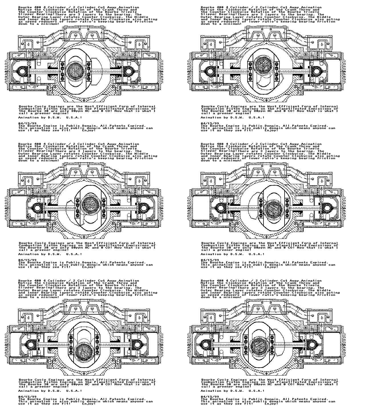
                      The most simple AND most highest torque motor per size that I know of with ONLY 2 MOVING PARTS... is the Bourke Engine:


                      Check out this video clip, you can obviously see how the rods could easily be sucked into a bifilar solenoid coil like in Bob Teal's patents.
                      http://projectbourke.com/vids/hndcrn.mpg

                      Here are a bunch of pics/clips of the Bourke project:
                      Project Bourke Engine! Now We're Gettin Somewhere!

                      The Bourke Engine! A Step In The Right Direction!

                      How The Bourke Engine Works by Bourke-Engine.Com

                      There are obviously some very capable people here with mechanical ability that could make this style of 2 piston engine for a Bob Teal setup. It could probably be much more mechanically simple as far as the fact goes that there doesn't need to be a combustion chamber, etc... Anyway, that has been what I thought would be the ideal Bob Teal piston setup.

                      Elias, maybe you can do a torque comparison to this concept compared to a regular piston/rod/crankshaft setup.

                      This of course isn't a comparison to rotary vs. solenoid, but since both can utilize Bob Teal's concepts, we might as well see what is truly the optimum solenoid/rod/shaft arrangement for maximum torque per input.
                      Sincerely,
                      Aaron Murakami

                      Books & Videos https://emediapress.com
                      Conference http://energyscienceconference.com
                      RPX & MWO http://vril.io

                      Comment


                      • Originally posted by Peter Lindemann View Post
                        Elias,

                        I apologize for my earlier post. At this point, I don't accept my objection either. I edited my original post and thank you again for running these tests. ANYTHING that increases the mechanical torque in these motors due to geometry improvements instead of extra electrical input is VERY ON TOPIC here.

                        Thanks again.

                        Peter
                        Thank you Peter,
                        This was only a misunderstanding between us and its over for sure.
                        I am starting to read the book you recommended more carefully (Solenoids, Electromagnets, and Electromagnetic Windings) to understand how electromagnets behave exactly, to be able to derive more precise relationships.

                        I was thinking that there must be an optimum geometry for rotary motors as well as piston operated motors which utilize the most out of the electrical input applied to the solenoid.

                        By the way, can a motor cycle engine be modified to replicate Bob Teal's motor? I mean is it wise enough to buy a small motorcycle engine for modification?

                        Regards,
                        Elias
                        Humility, an important property for a COP>1 system.
                        http://blog.hexaheart.org

                        Comment


                        • Deriving relationships

                          Originally posted by Aaron View Post
                          Hi Elias,

                          I think both piston and rotary have their advantages and disadvantages like everything else. Certainly rotary is much more simple to build and 1 moving part... a shaft in bearings.

                          The most simple AND most highest torque motor per size that I know of with ONLY 2 MOVING PARTS... is the Bourke Engine:


                          Check out this video clip, you can obviously see how the rods could easily be sucked into a bifilar solenoid coil like in Bob Teal's patents.
                          http://projectbourke.com/vids/hndcrn.mpg

                          Here are a bunch of pics/clips of the Bourke project:
                          Project Bourke Engine! Now We're Gettin Somewhere!

                          The Bourke Engine! A Step In The Right Direction!

                          How The Bourke Engine Works by Bourke-Engine.Com

                          There are obviously some very capable people here with mechanical ability that could make this style of 2 piston engine for a Bob Teal setup. It could probably be much more mechanically simple as far as the fact goes that there doesn't need to be a combustion chamber, etc... Anyway, that has been what I thought would be the ideal Bob Teal piston setup.

                          Elias, maybe you can do a torque comparison to this concept compared to a regular piston/rod/crankshaft setup.

                          This of course isn't a comparison to rotary vs. solenoid, but since both can utilize Bob Teal's concepts, we might as well see what is truly the optimum solenoid/rod/shaft arrangement for maximum torque per input.
                          Aaron,
                          This is very interesting, the only problem I see in it is the middle sliding part which may wear out over time and also waste some of the energy (I later on saw that it is claimed of no wearing out). I want to truly see if can an optimum geometry be derived using mathematical models, before attempting to construct something.

                          I'll keep posting as I find other interesting results.

                          Elias
                          Last edited by elias; 11-25-2007, 01:14 PM.
                          Humility, an important property for a COP>1 system.
                          http://blog.hexaheart.org

                          Comment


                          • Goodmorning everyone
                            Peter, as for the reedswitches, I am sure that the problem was the offcenter comutator, because when I could get only three pulses per revolution, I turned the comutator where the fourth pulse should be, and then if I pressed the comutator towards the reedswitch very hard, the whole thing bent a little bit, just to overcome the offcenter ( a half of milimeter or so) and the reedswitch did switch. Anyway, this is not important anymore, althought the reedswitches are good and easy to operate if you have your comutator right and everyone should start with them.

                            I did some experimenting. At first I disconnected and completely isolated all three outputwindings from each other and the circuit. I hooked everything up like in previous circuit without the isolated output. Also I put a computer fan near the transistors for cooling purposes. Again, I firstly tried to run the motor with only one transistor. Rhe RPMs were bad - only some 200 or 250 (i did not measure them) also the transistor got very hot fast and the fan could not handle that heat, the amp draw was about 0.8A at 24V (just like when isolated output was used). So I stopped the test.
                            Now I tried to run the motor with all three transistors. This time The RPMs were rising very fast and stabilized at about 2383 The amp draw was 1,48A at 24V. But the interesting thing is, that when using all three transistors, they did not get hot, only warm, nothing the fan couldn't handle. In the short test (a minute or so) the charging battery went up from 24.8 to 25.4V
                            Both batteries consist of two 7Ah 12v batteries in series. I should upgrade to bigger batteries, because this amp draw of 1.49A is not healthy for these little the batteries. Also the charging of the output batteries is happening to fast. I should charge and discharge them at C20 rate. But its good for short tests

                            Thank's
                            Jetijs
                            It's better to wear off by working than to rust by doing nothing.

                            Comment


                            • Congratulations

                              Originally posted by Jetijs View Post
                              Goodmorning everyone
                              Peter, as for the reedswitches, I am sure that the problem was the offcenter comutator, because when I could get only three pulses per revolution, I turned the comutator where the fourth pulse should be, and then if I pressed the comutator towards the reedswitch very hard, the whole thing bent a little bit, just to overcome the offcenter ( a half of milimeter or so) and the reedswitch did switch. Anyway, this is not important anymore, althought the reedswitches are good and easy to operate if you have your comutator right and everyone should start with them.

                              I did some experimenting. At first I disconnected and completely isolated all three outputwindings from each other and the circuit. I hooked everything up like in previous circuit without the isolated output. Also I put a computer fan near the transistors for cooling purposes. Again, I firstly tried to run the motor with only one transistor. Rhe RPMs were bad - only some 200 or 250 (i did not measure them) also the transistor got very hot fast and the fan could not handle that heat, the amp draw was about 0.8A at 24V (just like when isolated output was used). So I stopped the test.
                              Now I tried to run the motor with all three transistors. This time The RPMs were rising very fast and stabilized at about 2383 The amp draw was 1,48A at 24V. But the interesting thing is, that when using all three transistors, they did not get hot, only warm, nothing the fan couldn't handle. In the short test (a minute or so) the charging battery went up from 24.8 to 25.4V
                              Both batteries consist of two 7Ah 12v batteries in series. I should upgrade to bigger batteries, because this amp draw of 1.49A is not healthy for these little the batteries. Also the charging of the output batteries is happening to fast. I should charge and discharge them at C20 rate. But its good for short tests

                              Thank's
                              Jetijs
                              Jetijs,

                              Well done
                              Indeed you will be able to offer us a good estimation of the mechanical efficiency of Peter's designs and give us insight how to squeeze more out of it.

                              Your motor uses about 35 watts of electric power which means about one twentieth of a horsepower in conventional terms. Have you got any crude estimation of the mechanical power produced?

                              Elias
                              Humility, an important property for a COP>1 system.
                              http://blog.hexaheart.org

                              Comment


                              • Hi elias
                                No, I have not measured the torque yet althought I have all I need to do this the way Peter showed in his DVD with those two little scales First I must be sure that I have everything right, I mean the rise/fall times and so on, only then I will measyre the torque. Also we need to measure how much power we are getting back in the charging battery, because when I see how fast the voltage rises on the charging battery when the motor is running, I am certan it is A LOT I guess this is why Peter says I need to get a large capacity capacitor
                                Also this motor wont have very much torque, because the air gaps are not as small as they should be, also the startor is attracting the rotor only 1/3 of a revolution, all the rest time the rotor is moving by its inertia and starts to slow down. Afterall this is only a conceptual design that shows us the principes and lets us learn

                                Edit: I made a new video:
                                YouTube - Lindemann attraction motor video3

                                Thanks,
                                Jetijs/
                                Last edited by Jetijs; 11-25-2007, 06:14 PM.
                                It's better to wear off by working than to rust by doing nothing.

                                Comment

                                Working...
                                X