Announcement

Collapse
No announcement yet.

Electric Motor Secrets

Collapse
X
 
  • Filter
  • Time
  • Show
Clear All
new posts

  • Originally posted by Turion View Post
    Peter,
    Believe me, I have read every word of this thread, have watched your video several times, and understand that what I would be building would be nothing more than an experimental model. All I am looking for is as much information a I can get from those who have gone before so that I can take advantage of their experience. I do not know everything that Eric and Jetijs have gone through except for what has been posted here. From their experiences I have made tons of notes regarding the steps they took, their designs, and the materials and parts they used, and I intend to have a motor built that incorporates the best information available to me. I was just wondering if there was anything else you would suggest in addition to what has been presented at this site. Otherwise, I am going to have my motor built and then let the fun of trying to get it to do what it is supposed to do begin! I am used to beating my head against the wall, only I am one of those guys who doesn't give up until the wall is reduced to powder regardless of the consequences to my head!
    Hello Turion,

    Well, an idea came to me to combine an attraction motor with Joseph Newman's principles. Joseph Newman says a lot of things, but the thing that interested me, and I verified it experimentally, was the fact that the magnetic field strength remains the same for the same wire by increasing the wire length, thus consuming less current for the same magnetic power output.
    Some argue that the time constant increases by increasing the wire length as the inductance increases, but I tried to show here (http://www.energeticforum.com/renewa...nciples-3.html) that this is not the case.
    The problem with Newman's design is that he uses a magnet as the rotor and when it turns, it induces a very strong back-emf, because of the long wire length, limiting the motor's speed of operation, thus lowering the efficiency of the motor. But Dr Lindemann's design which uses a piece of Iron, as the rotor has not got this problem.

    Anyway, some idea to experiment with.

    Elias
    Humility, an important property for a COP>1 system.
    http://blog.hexaheart.org

    Comment


    • motor operation

      Hi Everyone,

      I truly believe that the following post is in the spirit of the 'electric motor secrets' discussion. I believe that in any case it would be nice to have a small summary of major concepts going into this motor, since this discussion isn't exactly brief.

      Through a series of fortunate events I am currently in a position to obtain a 3-D magnetic modeling program, so I can model the motor. With this information, making a COP>1 prototype should be easier to make.

      The only condition I need to meet before obtaining the program is to convince the assistant dean at my school that the design proposed in this forum is superior to other motor design available on the market, such as a switched reluctance motor.

      The following is what I have been able to piece together and am planning on submitting. I would really appreciate input on what I could add and pointing out if I have mistakes.

      I hope I am doing the right thing in writing this, becuase it will take up a bit of space


      Basic Design:

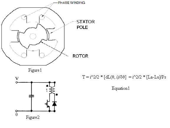
      Figure 1 illustrates the stator, rotor, and coils of a basic switched reluctance motor. The stator and rotor are made of multiple layers of thin laminations of silicon steel, an iron nickel alloy. The material is chosen for its narrow hysteresis curve. Additionally, the silicon lowers the conductance, which prevents eddy currents. Eddy currents are further reduced by using laminates separated by an insulating epoxy, such as metal epoxy. The coils are of thick gauge wire, which minimize resistive losses, as well as allow for a swifter coil rise time, which will be explained in more detail later.

      Basic Operation:

      If the rotor in figure1 is rotating counterclockwise then the rotor is in a position for the vertical stator pole pair to be magnetized and attract the rotor in the counterclockwise direction. Electrical energy is expended in raising the magnetic energy of the stator poles and then a reduced amount of energy is used in maintaining the magnetic field.

      Once the rotor pole is fully lined up with the stator, which would be the case if the rotor in figure1 was spinning clockwise with the horizontal stator pair active, the torque on the rotor goes to zero, because there is no longer a reluctance gradient. It is during this period of zero change in inductance that the energy on the coils is discharged, usually to be stored on a capacitor for later use.

      There should be no more magnetic field being produced by the time the rotor is becoming unaligned from the stator, as is shown in figure1 if the rotor where moving counterclockwise from the recently discharged horizontal coils.

      The rotor-stator geometry of figure1 is found in switched reluctance motors, induction motors, and pulsed DC attraction motors. There are other rotor-stator pole ratios, but they change the over all operation of the motors very little.

      Basic Circuitry

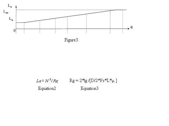
      When a sensor detects that the rotor is in the correct position to be attracted, a signal is sent to the mosFET gate, and a circuit loop is completed.

      If a sensor detects that the current is rising too high, a signal is sent for the voltage source to be disconnected and the mosFET gate to be turned off. The secondary coils then pick up the current, being the only path to sustain the magnetic field. The excess energy is then stored on the capacitor for later use.

      This latter stage is also used when it is desired for all the energy on the coils to be dissipated.


      Torque Production

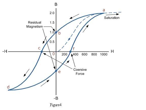
      Equation1 gives the expression for the torque production at a constant current. Figure3 shows how the inductance varies with the angular position, theta. From figure3 we can see that [dL(θ, i)/δθ] is a constant from the time the rotor and stator begin to align until they are fully aligned. La and Lu are the inductance of the coils when the rotor is in the aligned and unaligned positions respectively. Ps is the stator pole arc length in radians.
      One way to increase torque is to increase the change in inductance occurring in rotor alignment.

      Equations 2 and 3 give some insight into how this can be accomplished. N is equal the number of coil turns per stator. Rg is the reluctance of the air gap. lg is the air gap length. D is the diameter of the rotor. μ is the permeability of the free space.

      Air Gap

      From equation3 it is apparent that the air gap length is inversely proportional to torque production, but as the air gap becomes smaller, imbalances in air gap length and magnetic fields can lead to difficulties. A slight imbalance can cause the rotor to move in a radial direction and positive feedback occurs between the position and force until the energy on the coils is reduced. This leads to audible noise and can cause bearings to wear out. If both of the aforementioned imbalances are absent, then there will be no radial force on the rotor.

      Traditionally, motors that needed more torque where simply scaled up in size, rather than investing more money in accurate machining, self-centering bearings, and precisely made coils, but the raising cost of energy is making these methods more feasible solutions to increased torque production.

      Hysteresis Losses

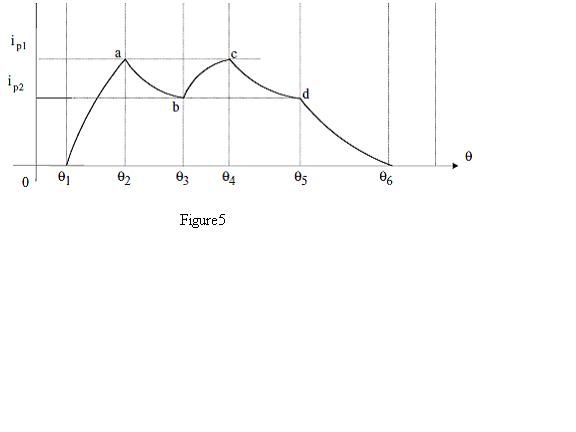
      Figure3's depiction of the inductance of a stator pole is accurate if the applied current is increasing or if it is held constant after being raised. This fact is apparent when looking at the hysteresis curve shown below.


      The inductance of a coil is a function of the slope of the hysteresis curve. For a soft ferromagnet, like silicon steel, the residual magnetization and coersivity are both very low, nevertheless, it is ideal to minimize the changes in the applied field, as in delivering isolated pulses of current.

      An interesting point to note is that the torque or mechanical energy production is proportional to current squared while the electrical power is equal to voltage times current which is only related to current in the first power. It seems reasonable to want to set in off in the direction of maximum current.

      Saturation

      There is a limit to how much current can be put through a motor. When the applied field is increased beyond the materials saturation point, an increase in applied field will not result in an increase in torque, which can be very bad, since, as the inductance drops, the rate of current growth increases and a lot of energy can be dissipated quickly.

      In order to avoid saturation, switched reluctance motors make use of the secondary coils and discharge the current, as seen in figure5. Figure5 leads to what is known as a torque ripple, which is the reduction in torque due to hysteresis losses.


      Stray flux losses

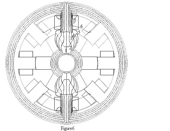
      Figure6 illustrates possible pathways for the flux lines, for a 8-stator 6-rotor motor when the rotor and stator are not aligned. Ideally all flux would path through path 4 or 5, the shortest possible air gap, but when the material reaches saturation in some segment that portion acts as if it were simply air, so the flux will take one of the other possible paths open to it, but not one that contributes to torque production.

      The more alignment that occurs between the rotor and stator, the less stray flux lines will arise. Additionally, the more alignment means that the material can handle more current before saturation occurs.

      Lenz's Law

      Raising the current on the coils requires more energy than simply maintaining the current. A steady current only has the resistance of the wires to hold it back, which is less than an ohm, so total electrical energy dissipation is quite low.

      The energy expended in raising the coil current is larger than the resistive losses, but the extra energy put into raising the current is not wasted, like resistive losses. The energy put into raising the current is stored in the magnetic field.

      The percentage of energy recovery possible from the coils diminishes with the amount of rotor-stator alignment. With a pulsed input, the total angle of rotation which occurs is minimal.

      There are other methods of increasing the rise time of the coils, rather than simply increasing the applied voltage. If the charging coil's inductance is decreased, it is able to rise faster. This can be accomplished by winding the charging coils out of two strands of wire that are wound at the same time. The ends are tide together, and you have what is known as a bifilar coil. The result is you have two inductors in parallel, which add inversely, hence a reduced equivalent inductance.

      For the recovery coils, one can make it out of a single strand, of a smaller gauge and more turns. The result is an increased inductance, which makes the decay time longer, which may prove to compensate for the added resistive losses.

      Swiftly changing currents can result in skin effect and proximity effect in wires. It may prove to be worth while to utilize Litz wire for the coils.

      Conclusion

      It has been the author's intent to simply provide a qualitative investigation into electric motor operation and point out that there is a window for improvement. Just how much improvement is available can be realize upon further investigation with a 3-D magnetic modeling program
      Progress comes to those who train and train. Reliance on secret techniques will get you nowhere.
      -Morihei Ueshiba

      Comment


      • Hi Chris
        Everythings sounds good to me. Maybe this picture also can be helpful to you:


        It is a magnetic simulation of the flux of my motor stator core. It was made by Steven (if I remember correctly) way beck when I started to build my second prototype

        Thanks,
        Jetijs
        It's better to wear off by working than to rust by doing nothing.

        Comment


        • ty

          Thx, forgot about that picture. It would be nicer than the one i used for the flux leakage.

          -Chris
          Progress comes to those who train and train. Reliance on secret techniques will get you nowhere.
          -Morihei Ueshiba

          Comment


          • No Back EMF in a ferromag coil

            Peter, What are your thoughts on this please?


            A Ferromagnetic core, torroidal wound coil, attraction, that has NO BackEMF.


            JLN Labs replicates Steorn's free energy motor


            Understanding the Steorn's effect by JL Naudin

            Ken

            Comment


            • Originally posted by Jetijs View Post
              This is because already at air gaps of 0.13mm the varying core inductance trend starts to show itself and it gets even more obvious if the air gaps are even smaller, like this waveform with 0.08mm air gap:


              All this need to be taken into account when building such motors. I should have realized this earlier. But what can you do, you never stop learning

              I hope this helps someone.

              Jetijs
              That waveform is more substantional than your explanation. Recently with Steorn I discovered some things and got an even deeper understanding of inductors. When I first saw your waveform I didn't think much of it but since I have some more knowledge now I want to adress it.

              Yes as the rotor closes the gaps the inductance will be changing in realtime. But your waveform shows something even more amazing. In theory the rapidly changing inductance will create an asymptotic slope. Almost exactly the same as an RL current graph (you can show this by simple formulas). That is the rate of current rise will decrease the more the inductance is being changed. But this means that the slope should die off.

              Yours is doing something very unusual on the other hand. Not only is it dieing off its slope is changing sign! Do you know what this means? The inductance has become negative during that short time period! This has some substantional implications. One of those is that your motor has been destroying energy . But if that negative inductance can be harnessed then an inductor will create energy just by hooking it to a battery. The current flow will be in opposite direction than a regular inductor thus charging it.

              Thanks to your work I have gained some new knowledge.
              Last edited by broli; 12-29-2009, 07:56 PM.

              Comment


              • final word on V3 motor? - torque?

                Originally posted by Jetijs View Post
                Hi all,
                It's been a while since my last post in this thread. I have nothing new to tell yet, because as Peter said, I am busy with other and not so interesting things right now. Anyway, I wanted to tell that last week I held a lecture about Bedini devices and Peters attraction motors at local particle physics institute. They organize seminars each month and many other enthusiasts like me visit those seminars. The main topics there is renewable energy. Anyway, I shared what I know and demonstrated my attraction motor. I used V2.0 motor to show the principles, I made everything so that I could put the inductive spikes to the front side capacitor using a switch when the motor was running. At 12v it rotated at about 3500RPM, was loud and consumed 2.4A of current. When I flipped the switch, the current consumption suddenly dropped to 1.4A, the motor became much quieter and the RPM's increased noticeably. That was a real eye opener for many of the people there, everyone was very interested. I will make a short video that demonstrated this, so I can promote this technology further and maybe someone with more free time and resources will be able to bring this thing to the next level.
                Also just then I realized why this current waveform of V2.0 motor looks like it does:


                This image shows the short current pulses that fill the whole 70 degree attraction window, they all are equal in duration, but nevertheless each next pulse gets shorter and shorter in amplitude. This is because already at air gaps of 0.13mm the varying core inductance trend starts to show itself and it gets even more obvious if the air gaps are even smaller, like this waveform with 0.08mm air gap:


                All this need to be taken into account when building such motors. I should have realized this earlier. But what can you do, you never stop learning

                I hope this helps someone.

                Jetijs
                I was wondering after following this whole thread and building two simple motors out of old series 1 motors. I was wondering what the final word was on the V3.0 motor? There seemed to be this issue with wave form and the torque.. are they resolved. I now have a machine shop and some resources to build one from scratch but I would like to know what the summary of this V3.0 design was...
                Thanks

                Comment


                • Hi cyberXena
                  Unfortunately I have not made any progress with the V3.0 motor at all, both motors are just sitting on the shelf and waiting some better days. I am busy on other things now. My problem is that my enthusiasm always jumps back and forth between different projects. Also I don't have a decent way to measure the mechanical power of the motor because it runs so fast and using Peters way I cannot get a decent data, also my flywheel is made out of acrylic and it melts at those speeds if I try to slow it down using friction from the leather belt. I think that in next month or so I will be able to get access to a decent dynamometer and then I will tests both attraction motors and the Flynn motor that is currently consuming all my time. Anyway, I think that the V3.0 motor has a lot of potential if the power ON times are chopped so that they match the current rise time and if higher voltages are used. So far I have not encountered any problems with that design and if I had to make a new one, I would make it just like that again. The adjustable timing and duty cycle commutator works like a charm
                  It's better to wear off by working than to rust by doing nothing.

                  Comment


                  • Originally posted by Jetijs View Post

                    Anyway, I think that the V3.0 motor has a lot of potential if the power ON times are chopped so that they match the current rise time and if higher voltages are used. So far I have not encountered any problems with that design and if I had to make a new one, I would make it just like that again. The adjustable timing and duty cycle commutator works like a charm
                    Thanks for responding your project has inspired me to build one now. I will use a lamination house here to cut down on the work a bit.

                    Proto Laminations' Electromagnetic Web Site

                    I have to think about the rise time vs power on chop time issue some more to understand it well. I am considering using a microprocessor to adjust timing and maybe voltage issues - I have prototyped some control circuits for the Arduino system. Pehaps this will be useful to others in the future. A couple of questions, please excuse me , What voltage did you mean in the quote 12v? 24V or more? I have run my motors up to 20Volts so far. Another question does your cnc system use standard position codes? (g-code etc.?) Did your speed-to-torque converter work well? I was planning on using one myself to connect my motor to an axial flux generator I'm building. They have less torque requirements than PMA's. I have several of the PMAs (Wind blue and others). I started to build a two motor version of the one I posted on this board, but then decided to wait on your project to see the outcome. But Now it seems to be the time to go forward. Thanks again for your response.
                    I hope to be able to tap your expertise (as time allows )as the project goes on.

                    Comment


                    • Price

                      Hi CyberXena,
                      I have seen that Proto Laminations site before, and I always wondered what the cost will be for such an attraction motor. Please let us know how much they quote. As far as I understand it they make actual laminations dies that stamp out the shapes rather then laser or flow jets. So I really wonder how expensive this service is.
                      Please keep us updated!

                      Thanks,
                      Steven

                      Comment


                      • Originally posted by Peter Lindemann View Post
                        Make a little 555 timer circuit and chop the LED front end of your optical commutator with a 50% duty-cycle and an ON-TIME equal to about 1.5 time divisions on your scope.
                        Originally posted by Peter Lindemann View Post
                        If you make the 555 timer circuit with a variable pot, you will be able to dial up the perfect chopping frequency to maximize the energy recovery. Once you know the right frequency, you can hardwire the circuit for those values.
                        THIS IS EXACTLY WHAT I NEED!!!

                        Idea officially stolen

                        So much great information in this thread... Applications in so many areas.

                        "Theory guides. Experiment decides."

                        “I do not think there is any thrill that can go through the human heart like that felt by the inventor as he sees some creation of the brain unfolding to success... Such emotions make a man forget food, sleep, friends, love, everything.”
                        Nikola Tesla

                        Comment


                        • field collapse directly used

                          Originally posted by LowTechIsCool View Post
                          Hi Everyone,

                          I truly believe that the following post is in the spirit of the 'electric motor secrets' discussion.
                          -------------------------------------------------------------------------
                          ---because there is no longer a reluctance gradient. It is during this period of zero change in inductance that the energy on the coils is discharged, usually to be stored on a capacitor for later use.

                          Hi all,

                          About 15 years ago I selected a VR motor (variable reluctance motor) for an energy recovery project. What I proposed actually worked and rather well to my surprise. What I did:

                          Some VR's come with both the + and - coil wires freed and not common(ed) in anyway. A local surplus store had tons of these. What I did was hook the pole coils up in such a way (using diodes of course) that when an energized pole field collapsed, it dumped the energy into the next pole. So using one with 4 or 8 poles on the lams was optimum. The only 8 I found had a badly bent rotor so I used a 4. So basically windings #1 and #3 got energized when their times came and windings #2 and #4 received the collapsing field energy from their neighbors, #1 and #3 respectively. IOW: #1 gets energized, turns off, collapses and in turn energizes #2. #3 gets energized, turns off, collapses and in turn energizes #4. Now we're back at #1 and it repeats. Now a VR stepper usually has 3 or 5 pairs of windings but whatever it was, it had an even number of wires and it worked.

                          Stalling the rotor you could feel the torque upon energizing a coil set and then feel a second (but smaller) torque when de-energized. As you might have guessed it ran best a one speed because the collapse does occur at some rate so there was some timing sensitivity.

                          This only worked because VR motors are attraction motors thus having NO rotor polarity to contend with.

                          Thought I'd share,

                          Greg
                          Last edited by gmeast; 03-08-2010, 10:49 PM.

                          Comment


                          • F-4 Gravity Motor

                            You may find this gravity motor - video - interesting.

                            YouTube - skycollection's Channel

                            "reliable motor and it can develop high speeds"

                            "FOUR COILS GRAVITY MOTOR, is a pulse motor with 4 air core coils and the rotor is working without friction, no bearings."

                            - Schpankme
                            Attached Files

                            Comment


                            • Scott's Motor

                              Originally posted by gmeast
                              Has anyone heard of or know if this motor ... I know this guy ... He built one of his early motors in my shop ... decades ago.
                              Nice to see he got a patent on it ... May 7, 1996 ... 5,514,923
                              The patent is moot as it is not an original idea. Here (attached) are just a few of the copyrighted drawings provided by Mr Bill Muller dated 1987. Let me add - WE discussed this motor at the Colorado Springs Symposium - Aug 1984.

                              also see:
                              Robert Adam - pulsed permanent magnet motor
                              John Bedini - Free Energy Generator

                              - Schpankme

                              Edward Leedskalnin said "keep the boys away from the girls."
                              Attached Files

                              Comment


                              • Please guys, stay on topic. Those motors have nothing to do with Peters attraction motor concept.
                                It's better to wear off by working than to rust by doing nothing.

                                Comment

                                Working...
                                X