If this is your first visit, be sure to
check out the FAQ by clicking the
link above. You may have to register
before you can post: click the register link above to proceed. To start viewing messages,
select the forum that you want to visit from the selection below.
Here is a relavant patent by a Davis. It has a lot of simularities with Teal and what we are trying to do here. Those more versed in this business like Lightly could give a comment: United States Patent: 4019103
"An electromagnetic motor and generator is disclosed having a pair of solenoids wound on a cylinder, each of said solenoids comprising three separate but connected windings. A magnetizable piston is positioned for reciprocation in the cylinder and is connected to a rotatably mounted crankshaft. A commutator connected to the crankshaft and interposed in an electric circuit selectively energizes the solenoids to cause rotary motion of the crankshaft. An additional circuit means is also provided for recapturing electrical energy generated in each of the solenoids upon deenergization of the solenoid by said switch. "
Sykavy,
Yes, the Davis patent has some similarities to this project. The big drawbacks in the Davis design are as follows:
1) The power is ON in the coils too long. You can see in the text that he is only hoping to recapture about 1/3rd of the electrical energy.
2) The stator iron structure is total insufficient to produce high torque.
I have the Davis patent in my files and could have used it as an example in my DVD, but decided NOT to because it did not represent a significant advancement.
In this project, we know exactly how to produce both high torque and recapture 80% or more of the electrical input. Davis may have envisioned performance on this scale, but his design is thoroughly incapable of producing it.
He does show separate coils for recovering the electricity, but does not show how to recycle the recovered energy for immediate re-use, as we have already done in this forum.
This patent is an interesting, historical footnote, but offers nothing in the way of advancing the art at this point.
I have had a chance to reread the Davis patent since I made the comments above and I have a few more things to add.
First of all, I would like to thank you for bringing this patent to the attention of the forum. There are actually a number of important issues the inventor is grappling with that are relevant to our discussion. There are also a number of important historic precedents established here.
The first thing I would like to say is that the inventor is still a little bit confused by the action of his machine. He refers to it as a "motor/generator" when in fact, it should be more properly referred to as a "motor/transformer". This is relevant to our discussion, because we are trying to build a system that behaves as a "motor/forward converter".
This patent clearly shows a simple schematic where energy from a collapsing coil is recovered to a second battery through a single diode. This predates John Bedini's monopole motor patent by 24 years, as well as all of the published circuits of the SSG project. So, the legal status of the "single diode recovery" configuration is clearly in the public domain. Bedini's SG can routinely recover 90% or more of the energy in the coil collapse, whereas Davis is hoping for 33% recovery. So obviously, the simple diode configuration is only part of the "secret" to efficient energy recovery, and Bedini's arrangement works considerably better than Davis.
Davis does show that by manipulating the coil design with various coils in parallel and series, that advantageous combinations can be found. This will always be true. There is plenty to be taken advantage of by the engineer who is advanced in his understanding of these issues.
On the mechanical energy producing side, Davis is very far behind Teal. He is essentially moving his iron plunger in an "air-core" coil situation, with no iron stator to channel the return magnetic flux. This will greatly reduce the amount of mechanical energy the machine can produce, as I demonstrate in my DVD. Plus, his commutator is ON all of the time, sending continuous power to one input coil or the other. So, Davis has not figured out how to maximize torque while minimizing electrical input.
On the electrical energy recovery side of the circuit, he shows one "run" battery, but THREE separate recovery batteries, each one for various parts of his complex coil system. By dividing the recovered energy into three parts, no single part could seem very substantial. He is also running the system like a transformer, where part of the input energy is directly "transformed" to electrical output in his tertiary coils. This directly loads the input power with back EMF to produce an output pulse. This process is totally absent in what we are trying to do here. It is also properly absent in Bedini's systems.
Historically, it is important to see that inventors have been grappling with all of these ideas for decades, and that the motor designs in this forum can be seen to have addressed most of these design issues.
There are lots of other little issues brought up in this patent, but that is enough for now. I believe that advanced students will find it very interesting to study this patent.
Thanks again, Sykavy!
[One final comment. When you look up this patent in the Google Patent system, you find that the schematic drawing is INTENTIONALLY corrupted to obscure the circuit. All of the circuit components are whited out to leave a meaningless FIG 5. You have to wonder who is responsible for this kind of scientific censorship? FreePatentsOnline has the full patent, including all the diagrams, and FIG 5.]
Thanks
I am glad you explained it! It helps me to understand some things better. I thought it was strange to call it a generator and I also missed the necessity of speedy collapsing of the coils being so important for recovery. I remember you told Jetijs to use two wires in parallel on his coil and not in series to get more magnetic pull and also it speeds up the collapse time. I didn’t realize it aided the recovery.
It is nice to see we aren’t so historically alone in this project and there is a continuity of development!!
Thanks again for the help!
I must say, that the audio quality was very poor on the video, but the material ROCKS! .... I was very impressed with the history that was pulled together of the old sources, it was very cool to see that others beside John Bedini has created motors that use the back EMF to getter advantage.
I am digesting this information, but has really expanded my world of understanding, I can build upon what I have learned from the SSG, and move out.
I am thinking my next project will be the Roto verter, since it has the least amount of work to simply buy motors off of the shelf.
Yet, if the designs that you guys are working on, hit oil, I will be very interested to head that direction as well.
It appears to me that on the film the motor that was demonstrated to charge a battery and do the mechanical work, and run a generator was a very high COP machine. It appears that one could take that motor, run it from a battery and end up with several charged batteries. Might be as good as the 10 coil that John B. has, if you scale up with larger motors.
What I am thinking is how does one store this energy once created? I have seen others use batteries, however they do loose their charge.
Maybee this is good enough that you have energy on demand, with a small battery bank to supplement large needs..
Anyway, I do wish to say a BIG thank you to Peter for sharing the theory, the schematics, and your vision that you have discovered from the early pioneers, and your own inventiveness.
I would like to get the exact motor used and if possible the information so I can duplicate that set up. Does anyone know how I can get that information. I appreciate the help.
Hi, I was able to stop the you tube video in just the right spot to see it is a Howard Industries motor. I can't tell but I think it is a 2.5 hp or maybe a .25 hp with an rpm rating of 6200. I have searched and I can't find one for sell. Do you have any leads as to where I could purchase one?? Also, I would love to be able to buy some u shaped steel laminations instead of canabalizing MOTS for them. If you know where to easliy buy them that would be helpful as well. I want to build several versions of Peter's attraction motor and also try to see if the flynn flux effect will help at all with it.
Hi there,
If you want U shaped cores, you can get them from Alpha-Core, Inc.
On the left choose: Magnetic cores, then at the bottom of the middle page choose: C-Cores Stock. They have lots of sizes and good prices.
Note, these are grain orientated cores which is a big plus.
I think what John Bedini actually invented was a way to turn Static electricity into a useful form. I think that is why he gets those off the scope high voltage spikes. I think the energy from the either is Static electricity. Of course this is just a hypothosis and I will now try to test that theory. Imagen if that was the case! Then you could match Lindemanns attraction motor with no back emf with a static generator which has no back emf and then use a bedini circuit to convert it to a useful form. Anyway that is just a thought I had and wanted to share with you guys on the forum. I have learned much from you and I wanted to contribute something even if does not amount to much.
Hello everyone
I am sorry about my slow progress. I have now removed all the "fuzz" form all the plate cuts. That was boring I decided to make the motor 50mm thick, that would be about 143 plates. I am ready now for gluing/bolting them together. I made a small test by gluing two spare plates together - everything holds very well. Also I wont need any insulation between plates, because the plates are already covered with a thin insulation material. In the mean time I have completed my CAD drawings. I used some Ideas form Steven. At first I wanted to use such bearings:
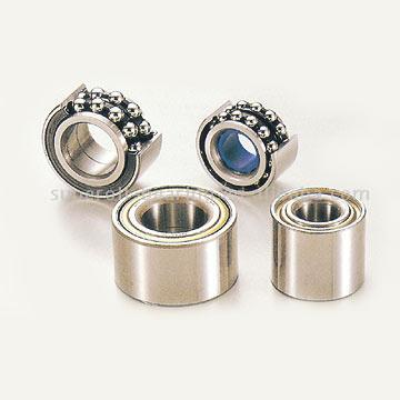
I had these laying around, but unfortunately they are too thick and with too big outer diameter for my purposes, so I will just go with standard one row ball bearings which are smaller in size and also thinner. Here are some pictures of my CAD drawings:
The inner square stator holding plates will be made out of polycarbonate so that there is about 6mm spacing between the stator poles and the polycarbonate. This is because the coils, that will be wound on the poles, will also eat up some space. This gap is further increased by about 3mm with the aluminum outer holding plates. I think, that 9-10mm should be enough for the coils. I made an .exe file that you can download and see my model in 3D for yourself. You can also make any part invisible or transparent to see what is behind there. Here is the file: http://www.emuprim.lv/bildez/motor.exe
You should be able to view this file with no need for additional software. The bolts and nuts there have no thread, because I have not learned to draw them yet, also it is not important. I designed it all so that I can use materials I already have to make this motor. Please take a look and tell me what you think.
Thank you,
Jetijs
Hello everyone
I am sorry about my slow progress. I have now removed all the "fuzz" form all the plate cuts. That was boring I decided to make the motor 50mm thick, that would be about 143 plates. I am ready now for gluing/bolting them together. I made a small test by gluing two spare plates together - everything holds very well. Also I wont need any insulation between plates, because the plates are already covered with a thin insulation material. In the mean time I have completed my CAD drawings. I used some Ideas form Steven. At first I wanted to use such bearings:
I had these laying around, but unfortunately they are too thick and with too big outer diameter for my purposes, so I will just go with standard one row ball bearings which are smaller in size and also thinner. Here are some pictures of my CAD drawings:
The inner square stator holding plates will be made out of polycarbonate so that there is about 6mm spacing between the stator poles and the polycarbonate. This is because the coils, that will be wound on the poles, will also eat up some space. This gap is further increased by about 3mm with the aluminum outer golding plates. I think, that 9-10mm should be enough for the coils. I made an .exe file that you can download and see my model in 3D for yourself. You can also make any part invisible or transparent to see what is behind there. Here is the file: http://www.emuprim.lv/bildez/motor.exe
You should be able to view this file with no need for additional software. The bolts and nuts there have no thread, because I have not learned to draw them yet, also it is not important. I designed it all so that I can use materials I have to make this motor. Please take a look and tell me what you think.
Thank you,
Jetijs
Jetijs,
Everything looks great. I couldn't open your .exe file, but I can see enough from the images here. A friend of mine and I have simulated a motor design very similar to this, and the performance is VERY GOOD. I believe you should be able to demonstrate COP>1 with this model if the air-gaps are small enough.
Just take your time, and do everything carefully. No need to apologize to the group. The "reward" for good work is in the result!
Also I migrated on a new image hosting place. Had to replace all the image links in most of my posts here. Unfortunately some of the images are lost permanently, I mean my CAD drawings from the previous motor design.
It's better to wear off by working than to rust by doing nothing.
Comment