Announcement

Collapse
No announcement yet.

Earth Battery SG

Collapse
X
 
  • Filter
  • Time
  • Show
Clear All
new posts

  • Originally posted by Iotayodi View Post
    Excellent. Which Iron wire did you use on that one?
    It was 24awg galvanized steel.
    It needs a squirt of more water. today the volts are at around 259mV and the mA at about 400mA.

    I am using a 0.47ohm resistor and reading volts and calculating ohms law for this and last year I used a meter. I must have been reading the meter wrong. this is really high!

    jeanna

    I think there is a short in the resistor.
    I get 1.2mA today which is much more believable.
    Last edited by jeanna; 05-28-2010, 09:52 PM. Reason: mA correction

    Comment


    • pseudo closed loop

      Originally posted by dragon View Post
      Out of curiosity I built AArons circuit with a bifilar coil for testing and it works quite well indeed. Without the kick back circuit it runs at 20ma on a 1.3 V battery and with the kick back in line it only draws 10ma. I ran it for about an hour with the battery start voltage of 1.327 and at the end it was bouncing the end number from 7 to 8 so there may be something going on there.. there is a scope shot of the circuit and the pics below of the circuit.... Great work AAron ! I haven't tried it with the SF coils yet....
      @ Everyone,

      The SG can run itself as virtually any other circuit can with proper "feedback".

      Tuning is required of course.

      I'll repost the diagram with apologies to Groundloop, Bruce and everyone
      else.

      But the correct circuit IS the one I posted. That isn't the NS or other
      circuit discussed, it is a conceptual diagram showing a power coil powered
      by one power source while recovering to a different storage bank (cap)
      for example.


      I will explain. The diodes are also correct.

      When the switch turns off, the spike goes to the cap.
      When the switch turns on, the circuit takes what is in
      the cap and only takes from the battery what the
      cap didn't supply. That is how it works.

      Positives of cap and battery or other power source are
      connected straight together.

      The purpose of the diode on the negative going from
      the battery to the cap? That is how you make the
      battery NEVER SEE THE CAP.

      With the diode on the negative,
      THE SWITCH SEES POS AND NEG OF BOTH BATT AND CAP.
      THE CAP SEES THE BATTERY - THE BATTERY DOES NOT SEE THE CAP.

      The battery negative does NOT see the negative on the cap.
      It CAN't! Look which way the diode is pointing.

      However, the negative on the cap obviously is connected to the
      battery negative and circuit so the circuit can make full use of the
      cap but the battery cannot provide anything to the cap.

      Bottom line, cap can provide to the circuit but the battery cannot
      give anything to the cap.

      If it did, you would be forcing the dipole to kill itself.

      This is one of various keys to make a self running motor, oscillator, etc...

      It can be done without an isolated winding but this should be experimented
      with first.

      In the jt's with lighting all the lights and also charging caps on the
      back end with isolated windings, those caps can feed back to the
      front in this manner to close the loop - or pseudo closing the loop.
      Sincerely,
      Aaron Murakami

      Books & Videos https://emediapress.com
      Conference http://energyscienceconference.com
      RPX & MWO http://vril.io

      Comment


      • Hi every one, I built a NS coil last week end fallowing lasersabers video series. Today the coil is hooked to my JT with 2 LEDs. At first, nothing was happening because the coil was showing only .341 vdc. Following a post made on lidmotors youtube channel, I mixed 5 tea spoons of Epsom salts in a quart spray bottle and whetted the coil, the meter went to .550 vdc and stayed there but the LEDs were not lit up. I then poured 2 table spoons of 3% hydrogen peroxide on the coil, the meter jumped to .674 vdc and lit both LEDs.

        Comment


        • @Aaron,

          >>I'll repost the diagram with apologies to Groundloop, Bruce and everyone
          >>else.

          Apologies accepted. I did overreact when leaving this forum.

          Maybe Jenna is right about someone making "anger vibes". LOL
          >>(I personally think our whole planet is getting beamed with anger vibes)

          I'm sorry for making a mistake with your drawing. I have also restored
          the images at my web site. I will continue to work in the COP>1 thread
          for now.

          Alex. (Groundloop)

          Comment


          • @all

            Really before adding additive witch are a good thing , there is a need to be able to make the coil tighter .

            The first time a saw a picture of his coil , i noticed how thick the wood he used was . And forgot about it .

            So either you redo the coil each time it goes down , so it is nice and tight to get it back up or MAKE it BETTER , NS coil did not have any problems with that , since a coil vise is included in the design ...

            The bolt and thick wood are not just for show ...

            Mark

            Comment


            • Stubblefield coil still alive an driving a secondary winding now

              @All
              My last attempt at the Stubblefield coil stayed alive for a day driving a JT light so I decided to add more primary windings and a small secondary to see if that actually worked---and it does. I was able to run a magnet spinner pulse motor from the primary and pull off AC from the secondary. It wasn't much so I ran it through a transformer to bump the voltage up enough to see it on a meter.
              Here is the video of it:
              YouTube - Self- running Stubblefield pulse motor with a secondary.ASF

              @ Aaron and Dragon I am anxious to try the recovery circuit out on this or on something else. It looks good. I guess the cap value has to be right for it to work.

              @screaminvern---Let us know how long the coil stays alive. I may build a small coil like Dragon's to try you epson salt/ hydrogen peroxide idea out on. On my latest coil I wound the coils very tight and carefully wetted each layer with distilled water. That might be why it is still working. I also used thicker T-Shirt material between the layers.

              @Jeanna---Shortly I am going to try your iron pipe coil. If that one lasted for two years in the ground and is still producing electricity, then we all need to study that design closely.

              @Groundloop---Thanks for being here.

              @Juju----If some of us don't respond sometimes it is just because we are swamped with projects that we are working on. Your work is important and what you share matters. We never know how many people are closely watching what is happening here and are interested.

              Cheers,

              Lidmotor
              Last edited by Lidmotor; 05-27-2010, 03:38 PM.

              Comment


              • feedback

                Originally posted by Lidmotor View Post
                @ Aaron and Dragon I am anxious to try the recovery circuit out on this or on something else. It looks good. I guess the cap value has to be right for it to work.
                It will work no matter the cap value.

                I just think that having a cap that is charged from 95% to 105% (pushing
                it a bit) on a single pulse would be optimum. I've experimented a bit with
                the values but need to do more.
                Sincerely,
                Aaron Murakami

                Books & Videos https://emediapress.com
                Conference http://energyscienceconference.com
                RPX & MWO http://vril.io

                Comment


                • How to build Aarons Pseudo Closed Loop

                  @ Aaaron and others who have built his pseudo closed loop circuit!

                  For experienced experimenters my questions will sound silly but I have a problem when I try to build this circuit. And possibly my questions have already been answered somewhere in the thread or in other threads (but I do not find the answers).

                  1) I do not understand the box "switch transistor etc..". How do I fit a transistor (and possible some resistors to bias the basis) in there? What triggers the transistor? One probably needs a trigger coil?

                  2) The coils on the core (with the markings N and S), how many windings do they have? What is the core, a toroid, a transformer core, an air core?

                  Sorry for all this questions, but I can not do anything with the circuit as drawn.

                  Greetings, Conrad

                  Comment


                  • the switch

                    Conrad,

                    That just indicates a generic switch that can be whatever you happen
                    to be using. It could be triggered by inductance, mechanical switch, etc...

                    If you have a coil that can pulse off and on, you already have it. If you
                    have another separate winding as a recovery, then you have the secondary
                    isolated already.
                    Sincerely,
                    Aaron Murakami

                    Books & Videos https://emediapress.com
                    Conference http://energyscienceconference.com
                    RPX & MWO http://vril.io

                    Comment


                    • Originally posted by conradelektro View Post
                      1) I do not understand the box "switch transistor etc..". How do I fit a transistor (and possible some resistors to bias the basis) in there? What triggers the transistor? One probably needs a trigger coil?
                      i dont want to pass over Aaron explanation, just to share my tought on this...

                      The switch may be a reed switch, or transistor triggered by coil or hall sensor. The point is to put a diode from the Battery negative, to the start of the secondary and cap negative... and another diode from the end of the secondary, to the cap positive and battery positive.

                      Originally posted by conradelektro View Post
                      2) The coils on the core (with the markings N and S), how many windings do they have? What is the core, a toroid, a transformer core, an air core?
                      as i understand you can apply this closed loop in whathever you want.. the windings should be the same on primary, and secondary i think...

                      imagine a bedini standard circuit, or joule Thief... you have a bifilar with trigger and run coil... than you wind a third winding and apply the circuit to that "third" winding.

                      if im not corrent please tell me, in that case i have understand it wrong!

                      hugs
                      Last edited by juju; 05-27-2010, 05:01 PM.

                      Comment


                      • a question...

                        @Aaron - maybe this will work without the secondary? and collecting the spike from the primary like standard bedini? maybe the diode from the battery negative, will have the same effect, if it cames from the end of the primary correct??


                        @Lidmotor thank you for your answer, i admire your work lots of time before i even attend the forum. was jonny that invited me and since that time im very happy for beeing here... like everbody i just want to feel part of this family, cause is the samme feelling that move us all, the feelling of experimenting, share and discover, the believe that energy is not what almost all the world think it is (mass).
                        Nobody likes to be ignored or putted apart, i just realize that first i should search very well what i want, before i bother every one with silly questions. An example, 2 pages ago i asked for help in a circuit to shut down my Led plant battery during day and fill a cap to discharge during night, i got ignored, and yesterday i found that you allready have a video showing that circuit.

                        Hugs and thank you!
                        Last edited by juju; 05-27-2010, 05:03 PM.

                        Comment


                        • This morning the coil was metering .214 vdc. Four squirts of Epsom salt water and 1 TB spoon hydrogen peroxide brought it up to .550 vdc. The LED wouldn't light until I tapped the core with a magnet. Just before I came in to post this, the coil was at .541 vdc, 4 squirts of Es water & one TB spoon of hydrogen peroxide, it went to .567 vdc and finally settled at .560 vdc. I noticed the galvanized wire is starting to rust alot.

                          Comment


                          • It was 24awg galvanized steel.
                            It needs a squirt of more water. today the volts are at around 259mV and the mA at about 400mA.

                            I am using a 0.47ohm resistor and reading volts and calculating ohms law for this and last year I used a meter. I must have been reading the meter wrong. this is really high!
                            That is high. Almost a half amp. I would keep doing the resistor and without the resistor with a digital and analog meter if you can. So far its not a good sign with galvanized wire.
                            Thanks Jeanna!

                            Comment


                            • pseudo closed loop

                              Originally posted by juju View Post
                              @Aaron - maybe this will work without the secondary? and collecting the spike from the primary like standard bedini? maybe the diode from the battery negative, will have the same effect, if it cames from the end of the primary correct??
                              Hi Juju,

                              It can be done with the SSG (simplified school girl).

                              I actually see the standard Bedini for recovery as the original trifilar and
                              the SSG as the modified one that came later.

                              Most everyone probably has seen this but the graphic below is the original
                              "dual battery charger" with the isolated recovery winding before the SSG.

                              The feedback method in certain variations has been shown in the Electric
                              Motor Secrets for a long time. Jetijs is the only one that ever did anything
                              with that or even noticed I think. There is a schematic or explanation in
                              there somewhere.

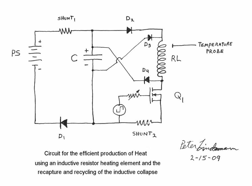
                              Peter's variation that we showed in the COP 17 Rosemary heater
                              thread (the original thread not part 2) shows a variation of the feedback
                              with the inductive heaters WITHOUT an isolated winding like the Bedini
                              SSG. That was one of the very first posts. Down below is that schematic.
                              I had difficulty getting that to work. I think I had to modify it a bit, but
                              it is easy enough to test.


                              Sincerely,
                              Aaron Murakami

                              Books & Videos https://emediapress.com
                              Conference http://energyscienceconference.com
                              RPX & MWO http://vril.io

                              Comment


                              • Stubby Dragon/Jeanna Stubblefield coil

                                @All
                                I made a small Stubblefield coil today like Dragon's and it worked. I used Jeanna's idea also and used a small iron pipe core instead of a bolt. I was surprised how well this worked and how easy it was to build. There are only four layers of wire on the 3" long coil and it is running a Joule Thief right now. It has a slight magnet effect but not enough to run a pulse motor. This one would be a good one to test out an electronic switching circuit on. I havn't wound a secondary on it yet but I expect that it will work just fine.
                                Here is the video of it.

                                YouTube - Dragon's Stuby Stubblefield coil---That works!.ASF

                                Lidmotor
                                Last edited by Lidmotor; 05-28-2010, 03:04 AM.

                                Comment

                                Working...
                                X