Announcement

Collapse
No announcement yet.

Imhotep's Radiant Oscillator Video

Collapse
X
 
  • Filter
  • Time
  • Show
Clear All
new posts

  • Originally posted by thedude View Post
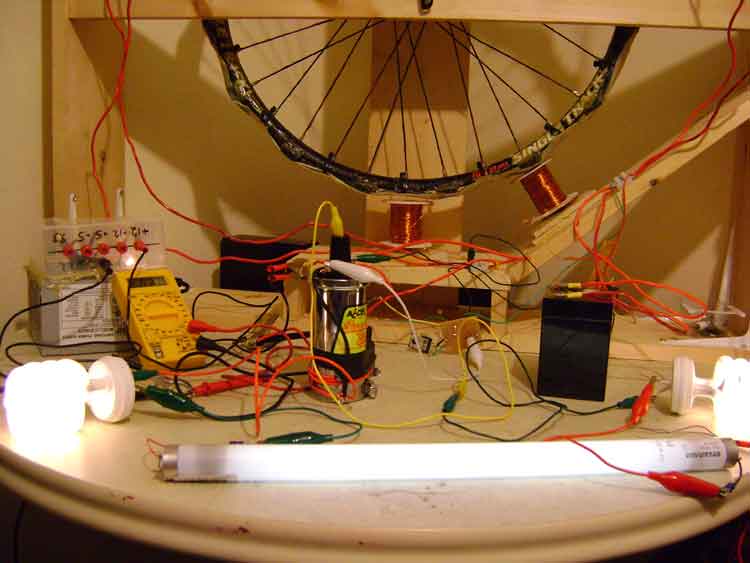
    I hooked up the ignition coil as the power coil in the bedini circuit and then set it into self oscillation mode. Normally the wheel goes into self oscilation mode while balanced between the magnetic poles on the wheel. Pretty bright and cheap and charging my secondary banks better than before with the wheel running! Current draw is only 190-200ma in the picture.
    Also observing a radiant effect whereby i can remove a connection in the series of bulbs and one or more will keep running with only one lead hooked up.
    WILD! I love this stuff.

    Heres a video to show what i'm seeing on Modvid.com

    Or on Youtube, which ever you prefer.


    I'm going to hook up my probes and try to get some scope shots to show.
    Thedude....

    Very well... you put a trigger coil on Bedini to activate Base transistor, and C-E activate the Car Coil? You save energy waste on relay or 555?

    I was trying to feed the car coil with BackEMF from Bedini but is insufficient, my motor is a little. You setup seems ingenius...
    Your time is limited, so don't waste it living someone else's life. Don't be trapped by dogma — which is living with the results of other people's thinking. Don't let the noise of others' opinions drown out your own inner voice. And most important, have the courage to follow your heart and intuition. They somehow already know what you truly want to become. Everything else is secondary.

    Steve Jobs. Apple CEO

    Comment


    • Originally posted by tai61 View Post
      howdy is anyone using a 555 driver circuit for the coil, im not getting as bright a light as the relays and would like to compare notes,any circuits for twin coils,double coils,cheers te
      Hi tai61
      the problem with the 555 is these no coil collapse to add the the ignition coil, the relay Back EMF is uesd with Low volts for the battery to light the bulbs.
      I THINK THIS IS WHATS HAPPENING?????????
      IMHOTEP can you verify this is correct Please
      I only have one coil and its small.the draw around 700ma at the best brightness.
      Im moving on to ignition packs. all fords in the UK use the same pack.
      Last edited by Bodkins; 08-23-2008, 07:47 AM.

      Comment


      • 555 driver

        thanks bodkins
        coil driver ran cfl not so bright, but charged gel battery good.
        It was set at 133hz so i added 2 pots to it and wound it up to the highest pitch, both darlington and bulb went coldest i had felt ,got abit more liht outa cfl.
        wanta hear some thing weird.
        was using one battery to run light so added diode in4007 to negitive lead returning to battery from light, bulb went really dim but battery started charging itself up.
        Has any body come across this,battery is running 555driver using 600ma, into coil ,plus a dim cfl and has gone up from 10.30v to 10.58v and climbing.
        Can any one explain,cheers te.

        Comment


        • Originally posted by tai61 View Post
          thanks bodkins
          coil driver ran cfl not so bright, but charged gel battery good.
          It was set at 133hz so i added 2 pots to it and wound it up to the highest pitch, both darlington and bulb went coldest i had felt ,got abit more liht outa cfl.
          wanta hear some thing weird.
          was using one battery to run light so added diode in4007 to negitive lead returning to battery from light, bulb went really dim but battery started charging itself up.
          Has any body come across this,battery is running 555driver using 600ma, into coil ,plus a dim cfl and has gone up from 10.30v to 10.58v and climbing.
          Can any one explain,cheers te.
          Im running a 555 for the wall socket cant run form primary battle it burns the circuitout.have problems viarable resistor keeps drifting,
          I have a ocillascope but crap at working out the frequency if you can help that would be great?

          What i have been doing is charging with a ampdraw at 50millamps one wire light just a glow.
          Not to great with building circuit but i understand what your doing.Will try turning up the VR high and charging the primary But i worryed about the High Voltant going into the battery will sent it after aline of bulbs to drop its down.
          at work at the moment will try the diode back to primary tonight.

          Take Care tai61

          Comment


          • Top Stufff

            Waterman24 and thedude (lebowski )

            Build a fan last night didnt get it into self oscillation yet need bigger pot.
            Just what to thank you two for a great idea.

            Comment


            • Re: 555

              Originally posted by Bodkins View Post
              Hi tai61
              the problem with the 555 is these no coil collapse to add the the ignition coil, the relay Back EMF is uesd with Low volts for the battery to light the bulbs.
              I THINK THIS IS WHATS HAPPENING?????????
              IMHOTEP can you verify this is correct Please
              I only have one coil and its small.the draw around 700ma at the best brightness.
              Im moving on to ignition packs. all fords in the UK use the same pack.
              The oscillations may not be as fast as the relay. When I was building the solid State Bedini, I found the 555 has limits to the ontime... Just a thought..
              See my experiments here...
              http://www.youtube.com/marthale7

              You do not have to prove something for it to be true. However, you do have to prove something for others to believe it true.

              Comment


              • Originally posted by theremart View Post
                The oscillations may not be as fast as the relay. When I was building the solid State Bedini, I found the 555 has limits to the ontime... Just a thought..
                Cheers but i cant get to see if its oscillatiing right yet the ajustments are to small
                this is the spec of the timer http://www.maplin.co.uk/Media/PDFs/N41FL.pdf it got up to 20khz with one twist

                would like to change the pot so i have better control.
                Last edited by Bodkins; 08-23-2008, 04:07 PM.

                Comment


                • Schematic, Please....

                  Thedude,

                  I would really like to experiment with this idea for triggering the light. I have an idea about why this works better than the 555 timer circuits, but I would like to duplicate your method before I theorize too much. I asked for a schematic of what you were doing a few days ago, but nothing has been posted.

                  Here is a short list of what I would like to know:

                  1) Is the ignition coil connected in SERIES with the Bedini SG motor drive coil, or in parallel with it?
                  2) Is the capacitor still across the primary of the ignition coil, or has that been removed?
                  3) Is the recovery taken from the SG coil and the ignition coil separately (parallel) or collectively (series)?

                  A schematic of the circuit you demonstrate in your YouTube film would answer all of these questions and clarify the process you show, Thedude. Thanks.

                  The reason this is so important is that current lighting technology can produce illumination at a rate of about 65 Lumens/watt. That is about what the CFL's do unmodified. Some of you have demonstrated what appears to be very high illumination of the modified 42 watt CFL with about 10 watts, using the relays, etc... These demonstrations, while not fully metered, suggest illumination efficiencies approaching 250 Lumens/watt, not to mention the recovered energy charging the back battery! Thedude, your latest demo could be approaching illumination efficiencies of 600 Lumens/watt or greater. If true, this is a major improvement over available technology. This is why I would like to duplicate what you have done, the way you are doing it. For that, I need your schematic.

                  This is the kind of breakthrough that Imhotep and I thought was possible, and why we Open Sourced the project.

                  There is no telling where this may go, if we can develop this to a standardized method. I look forward to your next post.

                  Peter
                  Peter Lindemann, D.Sc.

                  Open System Thermodynamics Perpetual Motion Reality Electric Motor Secrets
                  Battery Secrets Magnet Secrets Tesla's Radiant Energy Real Rain Making
                  Bedini SG: The Complete Handbook Series Magnetic Energy Secrets

                  Comment


                  • Just got home

                    Hi Peter and everyone. just got home from stretching in 130 sq yards of carpet. I am dying to post my set up in a more exact manner. I'm pretty hyped. Sorry about the wait. I'm doing it now.
                    EnergeticTube.com - Where technology goes Live!
                    ETaffairs.com - Your Portal Here on Earth

                    Comment


                    • Hi folks, i built the 555 version w/ single ignition coil w/ 32W helical bulb. pulsing 12v at about 72hz at around .8A produced fairly dim light. Then i decided to try a microwave transformer i had and at 24v,1A at same 72hz provided good light close to that of a 60W incand. bulb i have in the room. i used 2 microwave diodes in series to take off the collapse from the prim. winding of transformer and it seems to charge well but after doing some tests it appears to be a fluffy charge. it could be because the diodes are getting rather hot and causing wasted electricity or batteries need conditioning effect spoke of. whats interesting is if i put a regular 1000v,6A diode or even two in line like i am with the microwave diodes the bulb fails to light for some reason. not sure why.

                      Comment


                      • Originally posted by Peter Lindemann View Post
                        Thedude,

                        I would really like to experiment with this idea for triggering the light. I have an idea about why this works better than the 555 timer circuits, but I would like to duplicate your method before I theorize too much. I asked for a schematic of what you were doing a few days ago, but nothing has been posted.

                        Here is a short list of what I would like to know:

                        1) Is the ignition coil connected in SERIES with the Bedini SG motor drive coil, or in parallel with it?
                        2) Is the capacitor still across the primary of the ignition coil, or has that been removed?
                        3) Is the recovery taken from the SG coil and the ignition coil separately (parallel) or collectively (series)?

                        A schematic of the circuit you demonstrate in your YouTube film would answer all of these questions and clarify the process you show, Thedude. Thanks.

                        The reason this is so important is that current lighting technology can produce illumination at a rate of about 65 Lumens/watt. That is about what the CFL's do unmodified. Some of you have demonstrated what appears to be very high illumination of the modified 42 watt CFL with about 10 watts, using the relays, etc... These demonstrations, while not fully metered, suggest illumination efficiencies approaching 250 Lumens/watt, not to mention the recovered energy charging the back battery! Thedude, your latest demo could be approaching illumination efficiencies of 600 Lumens/watt or greater. If true, this is a major improvement over available technology. This is why I would like to duplicate what you have done, the way you are doing it. For that, I need your schematic.

                        This is the kind of breakthrough that Imhotep and I thought was possible, and why we Open Sourced the project.

                        There is no telling where this may go, if we can develop this to a standardized method. I look forward to your next post.

                        Peter
                        Wow. Hi Peter and all who are interested in my set up. Sorry for the delay in getting the schematic on here. Have had to work this weekend and just have been busy i guess. :P

                        I'm honored that anyone is interested in looking at something i've done, especially someone as noteworthy as you Peter.

                        I hope i've made a legible schematic that makes sense. I was very surprised to discover that i seem to have had 1 k resistor where i had thought there was 100 ohm! At any rate i had tuned it with a 1 k pot, checked the resistance and replaced with a resistor of 470 ohms where the pot was when i assembled the existing circuit. The 1 k ohm has always been in the circuit from the start. For the most part i've got all the circuits on my wheel in parallel, the bifilar coil (power) is parallel to the ignition coil as well.

                        I'm testing with 1- 12 volt 4.5 amp hour batteries on the primary and secondary now and have been running what i'm begining to think has to be COP >1 . At such a low amp output it ran all night last night with the source battery at 5.7 volts in the morning. I switched them and it climbed extremely fast up over 12 volts in around 10 mins or so.

                        I have more to add as well as some other test but i better post this and get back to add more later.
                        Thanks. Oh ya i hope John doesn't mind that i borrowed his schematic. Seems like a pretty nice guy from his vids. I'll take it down if so. :P

                        Last edited by thedude; 08-24-2008, 06:14 AM.
                        EnergeticTube.com - Where technology goes Live!
                        ETaffairs.com - Your Portal Here on Earth

                        Comment


                        • Hi TheDude,

                          So it looks like you have your primary of the Ignition Coil in parallel with the SGs primary, interesting. Just a note on your battery drain, You shouldnt take your battery below 10.5v (Better, no lower than 12v) if you want any lifespan out of it. It will naturally jump back up to 12vish when recharged, but this doesnt necessarily mean it has charged up to this level this fast.

                          You should see if you can run the primary of the Ignition coil off its own slave transistor (master/slave config).

                          Also, a quick group question, do all Ignition coils have their primary linked to the secondary?
                          "Once you've come to the conclusion that what what you know already is all you need to know, then you have a degree in disinterest." - John Dobson

                          Comment


                          • Ren : yes as far as I know all coils are auto transformers that have a common ground. hth

                            I have noticed a phenomenon when i first stated this experiment my coil would pulse the bulbs with no relay off the power supply because of the ripple that was passing through my variable power supply with no relay action at all. So when you are running it off a power supply keep in mind you are getting some ripple coming through the power supply that will tend to put the coil in oscillation mode. Im not sure if peter remembers months ago just briefly we discussed this. Something I though of the other day that i wasnt sure i alerted everyone about when they are doing their testing.


                            the dude : Your setup is amazing, GREAT WORK

                            i am working on catching up on all the posts. Had some schooling to finish up and shivas power supply in her computer decided to stop working on us.

                            As far as Bodkins, the three coil config is a interesting and an important aspect in the entire operation. And it appears what thedude is doing is his wheel is not spinning, the other coil combination appear to be putting the car coil in oscillation if hes not running it off a power supply. Unfort I dont have the large Bedini to confirm it. But i believe Peter does. So he might be able to confirm this for us. VERY VERY INTERESTING!

                            “Let the future tell the truth, and evaluate each one according to his work and accomplishments. The present is theirs; the future, for which I have really worked, is mine.”

                            Nikola Tesla

                            http://www.imhotepslab.com

                            Comment


                            • Originally posted by ren View Post
                              Hi TheDude,

                              So it looks like you have your primary of the Ignition Coil in parallel with the SGs primary, interesting. Just a note on your battery drain, You shouldnt take your battery below 10.5v (Better, no lower than 12v) if you want any lifespan out of it. It will naturally jump back up to 12vish when recharged, but this doesnt necessarily mean it has charged up to this level this fast.
                              With regard to the batteries low state of charge, i have discovered that they seem to have a much deeper state of charge than they initially did now after many charge/discharge cycles on my wheel with four bifilar coils. These 12v 4.5 amp hour bats no longer work like a normal one. They haven't seen any positive ion flow since i bought them! I will admit that in all my testing with these bats i have ran them down well below normal voltages, however that seems to be the name of the game until i can buy a PIC programmer and program an atmega chip to do the swapping. ( impossible for me to be around to predict and/or be around to swap my bats properly on a bedini monopole motor) I will say that they seem to perform admirably for batteries that have been abused.

                              Originally posted by ren View Post
                              You should see if you can run the primary of the Ignition coil off its own slave transistor (master/slave config).
                              I did actually try to tie in (parallel to the transistor in the wheel) a separate transistor circuit. it dropped the illumination down a bit with out much benefit. Not sure if i actually did anything like what you mean though.

                              Originally posted by **~Imhotep~** View Post

                              the dude : Your setup is amazing, GREAT WORK
                              Thanks Imhotep. Once again i have to say that i would be no where with out the inspiration of others here. I'm just looking and borrowing. :P But it feels really nice to get some positive reinforcement.
                              I'm running purely on 12v 4.5 ah batteries now and i'm discovering that impedance between the primary and secondary banks seems to affect the self oscillation. Have been testing in with bulbs in parallel and in series hook up. I've discovered that i am getting much better radiant charging when the bulbs are in parallel. Just an observation for now and an untested one at that. But it really seems that way.

                              I've been running the amps up to 400ma and seeing charge rates of 15.5v on the secondary frequency ranges of around 6500hz.

                              Thanks again. i truly hope what i've been able to do has been helpful.
                              Last edited by thedude; 08-24-2008, 05:13 AM.
                              EnergeticTube.com - Where technology goes Live!
                              ETaffairs.com - Your Portal Here on Earth

                              Comment


                              • the master and slave configuration would be well worth you looking into, especially if you have a multi coil machine. It basically allows you to use the same trigger signal to switch on other windings and/or coils. Of course all coils will fire at the same time, but this is what you want anyways. There is more details about it in other SG threads.

                                Imhotep, you should be able to do this with a little fan Im thinking. You shouldnt need a large replication to achieve self oscillation, just up the base resistance, really high. IF you can get a fan to self oscillate with high resistance then you have your trigger signal there, you could parallel another transistor and use it to switch the primary of the ignition coil.
                                "Once you've come to the conclusion that what what you know already is all you need to know, then you have a degree in disinterest." - John Dobson

                                Comment

                                Working...
                                X