Announcement

Collapse
No announcement yet.

Imhotep's Radiant Oscillator Video

Collapse
X
 
  • Filter
  • Time
  • Show
Clear All
new posts

  • Peter, it was not my intention to show this circuit as my own and I apologize if it looked so. Back then I just looked at various Bedini circuits and this was what I came up with when trying to combine some of them.
    Thanks,
    Jetijs
    It's better to wear off by working than to rust by doing nothing.

    Comment


    • Originally posted by Peter Lindemann View Post
      Lidmotor,

      I just tried Thedude's circuit with my SSG, and could not get it to work. The light only lit dimly when the ignition coil was in parallel with the motor coil. It worked the same (badly) with or without the capacitor across the primary. It did not light the light at all when wired any other way I tried. My system did not self-oscillate, but the current did drop to the 200ma range, but also slowed the motor down to a crawl. I'll try raising the base resistor or just build a stand-alone self-oscillator, like Jetijs shows.

      By the way, that circuit, with the three resistors of 2k, 10k, and 18k, was developed by John Bedini while I was working for him in 2004.

      Thanks for the extra details about your LB unit. Great work.

      I hope for better results tomorrow.

      Peter
      Hi Peter,

      I had mine working when I put it in series where I have put my bulb in circuit. That seems to give me good results...

      Cheers
      See my experiments here...
      http://www.youtube.com/marthale7

      You do not have to prove something for it to be true. However, you do have to prove something for others to believe it true.

      Comment


      • Originally posted by Peter Lindemann View Post
        Lidmotor,

        I just tried Thedude's circuit with my SSG, and could not get it to work. The light only lit dimly when the ignition coil was in parallel with the motor coil. It worked the same (badly) with or without the capacitor across the primary. It did not light the light at all when wired any other way I tried. My system did not self-oscillate, but the current did drop to the 200ma range, but also slowed the motor down to a crawl. I'll try raising the base resistor or just build a stand-alone self-oscillator, like Jetijs shows.

        By the way, that circuit, with the three resistors of 2k, 10k, and 18k, was developed by John Bedini while I was working for him in 2004.

        Thanks for the extra details about your LB unit. Great work.

        I hope for better results tomorrow.

        Peter
        Peter,

        I took me over 2 hours to get mine to work. My initial tries ended with results like yours. I basically stumbled onto the right resistance on the transistor base and my little SSG started to self oscillate. From there I just kept trying different resistors until I got the CFL to light at about half brightness and drawing about 230 miliamps. It was also charging on the backend at that point. It was running on 12v and if I increased to 24 volts (added a 2nd 12v battery in series) the brightness dramatically increased but so did the current draw. This needs more work but its a good start. Also, on the LB unit it takes about 1 amp to make the two lights bright. Good news is that with the lid on the box you can hardly hear the relay. I think that tomorrow I am going to build the stand alone self-oscillator that Jetijs showed. Is it possible to put a voltage multipiler somewhere in here to bump the voltage up and make the lights brighter?
        Lidmotor
        Last edited by Lidmotor; 08-25-2008, 06:22 AM.

        Comment


        • self charge

          Originally posted by Bodkins View Post
          tryed return the negative not got the same result will keep playing but i think the darlingtons my be adding somethin but hey what do i no!!
          is it still climbing?
          thanks for trying bodkins,
          changed 12kR witha 20 k pot when added duty cycle,and coil adjust by ear until highest audible,also forgot to say added 2200uf 250v cap between coil output and light,
          In reality it dosent seem to be a charge as it only goes up in small amounts slowly,and only to about 0.5 v of what i started with.but without the in4007 it keeps going down ,with it it keeps going up.
          Could it be that normally im loosing charge thru. the neg. post with each coil collapse,cause the circuit is based on emitter ,and diode is just helping with ths loss.

          would like to take this chance to thank IMOTEP for his open forum on his light
          and all the effort he put in to make us understand it, and for PETER for helping him,and for Aaron for his book,
          AND MOSTLY I WOULD LIKE TO APPOLIGIZE FOR ALLTHE DUMB QUESTIONS I HAVE I HAVE ASKED IN THE PAST AND MANY MORE IN THE FUTURE

          Comment


          • Secondary charge

            Hi again folks, I'm curious why nobody is testing the load worthiness of the captured primary coil collapse energy to the sec. batt. whether it be from an ignition coil or a microwave transf. I understand here that light output efficiencies might be exceeding typical ac household setups if thats the case great then maybe ill have to tune this 555 setup better w/ ign. coil, however what i'm finding is the meters showing good charging of sec. batt. but when swapping them, the sec. charged batt. cant carry a load for very long without voltage dropping quickly below previous mark. not trying to rain on what seems to be positive projects, just wondering why its not being discussed. maybe its a matter of conditioning batts. or using an inverter to power loads as Peter once said, i think, was needed to utilize the radiant charge. just curious.
            Ty

            Comment


            • Charge...

              Originally posted by SkyWatcher View Post
              Hi again folks, I'm curious why nobody is testing the load worthiness of the captured primary coil collapse energy to the sec. batt. whether it be from an ignition coil or a microwave transf. I understand here that light output efficiencies might be exceeding typical ac household setups if thats the case great then maybe ill have to tune this 555 setup better w/ ign. coil, however what i'm finding is the meters showing good charging of sec. batt. but when swapping them, the sec. charged batt. cant carry a load for very long without voltage dropping quickly below previous mark. not trying to rain on what seems to be positive projects, just wondering why its not being discussed. maybe its a matter of conditioning batts. or using an inverter to power loads as Peter once said, i think, was needed to utilize the radiant charge. just curious.
              Ty
              I think there have been sooo many variations of the setup that we have not taken the time to test. You do say that they do not hold charge, but my next question is, what size battery, and how much amperage did you use?

              I agree with many Bedini setups there is a "fluffy charge" yet if you apply the correct amperage, it stiffens up quite a bit.
              See my experiments here...
              http://www.youtube.com/marthale7

              You do not have to prove something for it to be true. However, you do have to prove something for others to believe it true.

              Comment


              • Hi thanks for reply, i used 2-12v,7ah in series 24V charging another identical set 24V. I was powering the light with only 555 timer and npn transistor using microwave trafo as said in prev. post. light output i would say was like using a 50 watt incand. and so i powered bulb 10 min. then swapped for a couple times and charge wasnt holding very well, current was 1A. now granted it may be because of heat loss at diodes or maybe batteries are getting weak not sure but in prior experiments w/ bedini solid state pulser using 2 farad cap discharge the charge was pretty solid. so its probably my setup.

                Comment


                • Originally posted by Jetijs View Post
                  Peter, it was not my intention to show this circuit as my own and I apologize if it looked so. Back then I just looked at various Bedini circuits and this was what I came up with when trying to combine some of them.
                  Thanks,
                  Jetijs
                  Jetijs,

                  Whose circuit is this?

                  Carl
                  shema.gif
                  Last edited by hh1341; 08-25-2008, 03:21 PM.

                  Comment


                  • That is John Bedini's circuit, just like Peter said
                    It's better to wear off by working than to rust by doing nothing.

                    Comment


                    • yesterday to have fun i took the imhotep oscillator hooked up one wire to modified bulb and other wire to the tube (wrapped around glass at mid way up on spiral ) and it drew .2 amp lit the bulb in the local area of the wrap and ionized the whole house .very interesting effect .also worked on ss version with ok results thanks jedijs and ren
                      “Let the future tell the truth, and evaluate each one according to his work and accomplishments. The present is theirs; the future, for which I have really worked, is mine.”

                      Nikola Tesla

                      http://www.imhotepslab.com

                      Comment


                      • John Bedini's Circuit

                        Originally posted by hh1341 View Post
                        Jetijs,

                        Whose circuit is this?

                        Carl
                        [ATTACH]1053[/ATTACH]
                        Carl,

                        Please let me answer this, as I have first hand knowledge of where this circuit comes from. I worked for John's company, Energenx, Inc., from March of 2004 until August of 2005. We did extensive investigations with this circuit during this time period. It is one of two primary "solid-state" oscillator circuits that John developed for his battery charging technology. This circuit was released some time ago, but to the best of my knowledge, the second circuit we investigated was never published by John.

                        This circuit, as shown, is what we referred to as the "self-oscillator". It had long been observed that if a large enough resistor was used in the base loop of an SG type motor, the circuit would self-oscillate without the rotor turning. In the SG, this effect was generally considered an unwanted nuisance. The fact that this did happen eventually lead John to develop a circuit that did this on purpose. All of my lab notes from that period show the circuit with a 1K resistor instead of a 2K resistor, but otherwise, it is identical. The circuit obviously works with either value.

                        Here is how it works. When the circuit is turned ON, the 18K resistor forward biases the transistor to conduct current, since the base is in the current path of the 18k and 10k resistors across the power supply. This energizes the power coil, which in turn energizes the trigger coil. Since the trigger coil is wired in the opposite direction, it produces a voltage which conducts current up through the closed loop including the 10k resistor, the 2k resistor, the trigger coil, and back to ground. Current in this loop reverse biases the voltage at the base of the transistor, turning the transistor OFF. When the transistor turns OFF, the energy of the magnetic field in the primary coil discharges through the secondary circuit, through the diode to the charging battery. As soon as this discharge is complete, the cycle repeats. The frequency of this oscillation is determined by the inductive rise-time of the coil and the values of the resistors.

                        This circuit produces the characteristic "h-wave" of the Bedini Radiant Chargers.

                        John published this circuit a number of years ago in the SSG forums, so everyone is free to use it, or develop other variations of the circuit as the case may be.

                        Peter
                        Peter Lindemann, D.Sc.

                        Open System Thermodynamics Perpetual Motion Reality Electric Motor Secrets
                        Battery Secrets Magnet Secrets Tesla's Radiant Energy Real Rain Making
                        Bedini SG: The Complete Handbook Series Magnetic Energy Secrets

                        Comment


                        • strange working

                          Hello,

                          I've succeed constructing and getting all the parts of the circuit but don't work properly. Here you have my component details:

                          Ignition coil (you can see it in the pick, I don't have any details)
                          12V relay
                          4,7uf 60V and 100 ohms for the snubber.
                          capacitor (I don't know how to get the one that you said, I have different options, 450 V 20uf and 300V 5uf)
                          15W bulb

                          with this components and the circuit hooked up the current flow is 7amps and the light is lighting up. I think I have hooked the circuit correctly. Besides the relay has a green arch, is that normal? I may miss something or maybe my components aren't good. What you think?

                          Here you have my pictures of my circuit.


                          Thank you all are great!
                          Dancing the dance of Shiva in the middle of a meleé of particles, that is to say in the vacuum

                          Comment


                          • keeps on evolving

                            Lidmotor I love the Boxed version! I studied your videos carefully as i built my first 9volt relay oscillator. Yours is the most functional of any design i'd seen. Awesome work man! I'm glad your having some luck with a SSG ciruit as well.

                            Thanks for clarifying on the master and slave config for a single trigger Ren. I had considered that my build was incorrect with each circuit ran parallel together. I had imagined that the magnet spacing on the wheel with reference to coil positioning would become critical with that config. Being that i was building out of wood and would probably have variance in the timing with that design I felt it was better to have each circuit trigger its own power. Not sure i knew what i was doing at that point, pretty sure i still don't. lol :P I do want to do a slave/master type trigger setup in the future though.

                            I have wheel running really well now on 3 bifilar coils, two running the wheel and the other pulsing the ignition coil. I am finding a higher amperage here at 1.03 amps, however my charging has gone up considerably. For some reason having the ignition coil pulsing the lights is creating a different type of radiant negative charge than i was dealing with on a straight bedini type wheel. Much more radiant i think. Here is a video of me just messing around with a new setup on modvid.com. Or at Youtube Its not meant to illustrate anything in particular. Maybe a little less talking in the next video. The amp draw while self oscillating compared to when the wheel is pulsing is marginal at best and produces the best charging i've seen so far.

                            Jetijs, i tried John's self oscilating circuit out last night and had poor results for some reason. I balanced each resistance across the appropriate legs of the transistor with a good ohm meter. I ended up with some shorting for some reason. I think once this circuit is self oscillating it might solve the impedance issue between the banks that can inhibit self oscillation on a SSG circuit. I wonder if i should have used the 2n3055 instead of mjl21194 ? I had a bad day yesterday leaving me questioning the continuity of 2 of my good bifilar coils (only one was in my wheel) Life goes on. Tested 2 new ssg ciruits and the self oscillator yesterday with out a single positive result. Some one sound the french horn!
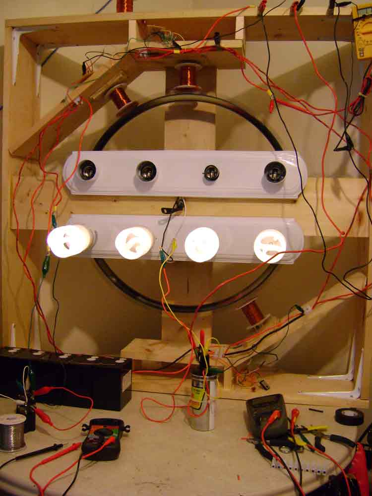
                            One of the ssg circuits i was making was for a 2 pole (separate trigger and power) on a fan motor that i had running really well at one time. I built two 12volt lithium ion batteries out of two Energizer E-squared 6volt bats in series to power it(not intended for recharging, but i am!). They charge up fast. When i had this coil going before it was really humming in self oscillation. I think it will make a great fan/portable light if i can get the bats to switch on a timer from primary to secondary. These seem to nearly charge as quick as they discharge while driving my large wheel, i think they will do real well on the small fan motor while driving a light when in self oscillation.

                            I'm going to make another video to show a few things with instrumentation at a little higher amps. I've found that the increase in amps ( up to 1 amp or so) pays in charging on the secondary banks as well as a high enough rpm on the wheel to eliminate the issue of self oscillation altogether. (wheel pulses quick enough for even lighting) In my model the impedance between the banks can make self oscillation difficult. I'll try to get some better instruments out and make another video to show a slightly higher product. Sorry if i sound like a complete novice in them.

                            PS- I still have no problem reproducing 180ma draw with those three bulbs in my first vid. I'm trying to figure out why series bulb hook up doesn't seem to charge the secondaries as well.
                            Last edited by thedude; 08-25-2008, 09:25 PM.
                            EnergeticTube.com - Where technology goes Live!
                            ETaffairs.com - Your Portal Here on Earth

                            Comment


                            • John Bedini's Circuit

                              John published this circuit a number of years ago in the SSG forums, so everyone is free to use it, or develop other variations of the circuit as the case may be.

                              Peter
                              shema.gif
                              Peter,

                              On behalf of us all , thank you for explaining this circuit.

                              Carl

                              Comment


                              • Imhotep's Radiant Oscillator---Solid State

                                More really good news!! I built the John Bedini oscillator circuit that Jetjis posted and ran the Imhotep Lite using it . It worked great. I added a 5K pot where the 2K resistor went to adjust the frenquency and added my 25 Ohm rheostat where the on/off switch went. I used an AM radio tuned to a null station to tune it. I used a bifiliar coil like I used in my first Lidmotor SSG that had a mismatched coil ratio and it still worked. Here is the video YouTube - Imhotep Radiant Oscillator Lite -- Solid State

                                Cheers,

                                Lidmotor

                                Comment

                                Working...
                                X