 Tweet
Tweet
Hello everyone,
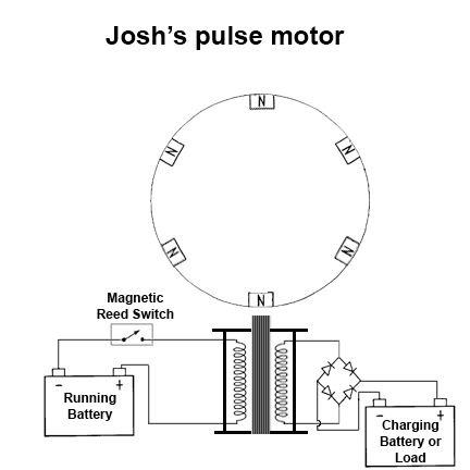
I have created a pulse motor inspired by John Bedini's early patents. I am doing to tests to compare mechanical make/break driving against transistor based driving methods. Right now I am still testing the mechanical driving.
Here is a schematic of how I run it now (after testing I found bridge across reed switch is not needed as long as a load is on the secondary).
This is my first video of it in it's basic form...
YouTube - Monopole Pulse Motor
I have found peculiar things...let me explain
1.Even though the two windings are electrically isolated, I can get either wire of the secondary to arc back to either lead of the primary (one wire energy flow)
2. I can store up to around 250v in a parallel bank of 12 1500uf capacitors, which, I can then dump into a resistive load and get usable power...but, when I attempt to dump it into an inductive load such as a transformer, I get no result...I mean nothing...no spark, no voltage spike on the secondary, the voltage just vanishes.
3.The Arc that usually occurs in the reed switch vanishes if I give the collapsing field somewhere to go (secondary load)
Also, a direct load on the secondary (other then a battery) makes the motor run significantly slower...a capacitively coupled load on the other hand has no problem getting up to full speed.
I will be doing more tests soon...so if anyone can elaborate or provide any insights into any of the things that I have noticed...or that you or others have noticed, I am all ears and would love the feedback


 I have suspected that for a while and so I have always used a single diode on my mono-coil trifilar set ups!
  I think if you put a diode in parellel with the reed switch (in the opposite direction to the current flow so all current from the battery still flows through the reed switch ) it may increase the life of your reed swithces though may sacrifce the rapid on/off time that is provides... just a guess... could be wrong!
 ...however, it is unstable...So, I run it at 23v and have no problem with arc/heat
 Thank you both
")

Comment