Announcement

Collapse
No announcement yet.

Mechanically Driven Pulse Motor

Collapse
X
 
  • Filter
  • Time
  • Show
Clear All
new posts

  • #16
    i was wondering... See the image, what if we added more coils where arrows are pointing (well even anywhere around the wheel)? wont it generate more electricity?


    P.S. im not rly into electronics or physics so bear with me plz.. i just have lots of ideas flowing and figured i should ask ;]
    Last edited by roxaz; 08-25-2008, 11:37 AM.

    Comment


    • #17
      reed motor

      Hi Raiidant this is my exact setup that I did in the past.Konzen helped me to do this.Yes it generate 200v or more.
      I removed the plasma from the reeds by adding a a big zener diode parallel to the reed.
      Thanks.

      Comment


      • #18
        @ Roxaz
        i was wondering... See the image, what if we added more coils where arrows are pointing (well even anywhere around the wheel)? wont it generate more electricity?


        P.S. im not rly into electronics or physics so bare with me plz.. i just have lots of ideas flowing and figured i should ask ;]
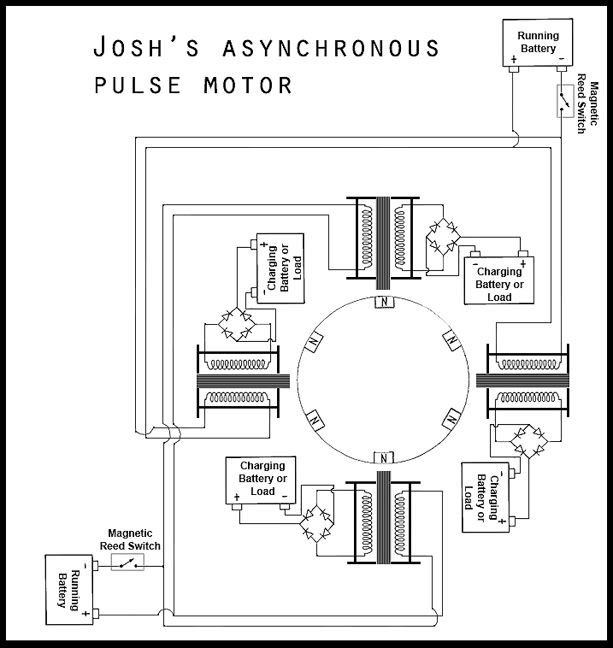
        If you mean un-powered coils to translate the on/off field...yes it will, but it will produce a drag on the motor (I'm basing that off of an iron cored coil...unsure if an air coil would or not), but, that would slow it down and draw a little bit more power...But, there's only one way to find out if the benefits outweigh the cost. I will make a coil that I can slip a core in and out to see what kind of energy it makes. I have seen about 19v by just spinning my rotor by hand over the bifilar coil. So it's worth a try

        But, I am unsure when I can do that because this is what I am planning to build...


        There are two pairs of coils (each pair on a separate circuit)...the geometry allows the linked coils to be aligned at any magnetic moment...but, the two pairs will always be out of sync, due to the trinity of the rotor. (six magnets can be looked at as 2 sets of 3)

        I expect that the RPMs will increased substantially, and also that there will be constant spikes of energy...currently I have a lag time, but the alternating pulses will give me twice the charging speed. (note that in the drawing the outputs all go to separate batteries/loads, in the actual model they will all go to the same load...probably many batteries in parallel).
        Last edited by Radiant-1; 08-25-2008, 01:24 PM. Reason: Forgot some explanation of what I expect from this setup...

        Comment


        • #19
          Single coil BEMF

          @vzon17
          Here is my circuit showing how I modified my bedini motor to run with reed switch and it charges the cap up in a few minutes up to 200 volts or more.
          My coil is just a single wound coil of 24 gauge wire and I put the reed switch right on top of the coil so the magnet just misses it as the wheel spins around. with some adjustment it spins pretty fast.

          So I am wondering if this kind of setup can be used to charge batteries with radiant energy the same way as the regular school girl motor. It would require some interval timer to dump cap I suppose. I will try it in my spare time.
          The answer is yes, something like that can give you the back spikes you need to do some charging. I have disconnected the secondary of my motor and used just the BEMF across the reed switch. I can't say if it is better or worse...but I did notice that the energy seemed to be the same. Meaning when I disconnected the secondary, the reed switch became more powerful. It charged the capacitor bank just as fast...However, my reed switches are under a slight vacuum, so the resistance is much lower then the diodes...so in that mode I could never get the plasma arcs to go completely away. But when I added a load to the secondary with absolutely no rectification on the reed switch it vanishes

          Comment


          • #20
            Originally posted by Matthew Jones View Post
            Why not just diode off the primary to another battery. Instead of using the BackEmf alone to charge another battery. Use all 3 currents that show up.
            The emf coming 0uta the battery, The radient spikes that show up from 2 North collisions, and the backEmf that settles back to the wire.


            Or Load a low farad cap BackWards and during your off time backpop the battery with a forward discharge. Or another cap in front of battery. Reuse the energy.

            The other thing, And this is opposite of what Mr Lindemann says. The bridge is the way the go if your after that Implied Negative Energy. And thats whats coming out of that secondary coil. Not Regular EMF. Put 2 or 3 Bridge rectifiers after the one you have. Take the positive and negative of the one you have and hook them AC outlet on another BR.

            The Voltage will grow. Thats what negative energy Does. Grows through resistance.

            If you have any amperage at all its bleeding via transformer effect off the primary coil. Adding Bridge rectifier will reduce the MEASURABLE amperage. But Negative energy and whatever it has for amperage is not measurable.
            In other words If you want to use it, then grow it out, and then put it to your battery. Or like I said about the previous scenerio Use it to backpop your run battery.

            What you have is nifty. The problem with it, and no else bothers to mention, is if you want true extra energy out of a system than YOU MUST stay off the ground. Do NOT send any current to ground. Every time you do you waste it. And in a motor there is no need to do it.
            The motor simply channels the photon energy emmitted from the Divergant and Non Divergant energy flow on your wire. So why consume the energy on the wire if you don't have to?

            Good work, hope to see you go further.

            Cheers
            Matt
            Perhaps I missed something but won't the "back emf" reverse charge the primary battery on that schematic... I mean, shouldnt the diode be connected to the primary positive and not the primary negative?

            and if the primary battery voltage is higher than the charging voltage the primary battery will discharge directly into the secondary battery through the coil even when the reed switch is in the off position.
            Last edited by Sephiroth; 08-25-2008, 08:20 PM.
            "Theory guides. Experiment decides."

            “I do not think there is any thrill that can go through the human heart like that felt by the inventor as he sees some creation of the brain unfolding to success... Such emotions make a man forget food, sleep, friends, love, everything.”
            Nikola Tesla

            Comment


            • #21
              You tell me!!!

              I have a look at the schematics and i have a sugestion for you guys!!!!
              I have numberd the coils to explain myself better. If you have the coil #4
              coupled the iron coil to #2 and coupled #1 with #3 i think you doubled the spikes going trough the diode. = more energy out.
              PLUS. If you put 2 iron core coupled this way i think the EFFICIENCY of the
              pulses will increase because the pulsed coil will send a south pole to the other coil..This way ATTRACT the comming magnet...Right???????MyPulseMotor2.jpg

              Give me feed backs on this please....

              Alain
              Last edited by peper10; 08-25-2008, 10:59 PM.
              Hope die last!!!

              Comment


              • #22
                more coils more energy

                roxas
                quote:i was wondering... See the image, what if we added more coils where arrows are pointing (well even anywhere around the wheel)? wont it generate more electricity?

                I believe your answer is yes, but you will also be using more energy to make more energy. Line those coils up with your magnets, or stager them like radiant1 suggests or make additional rotors that are out of phase as the first rotor and get some more coils around those magnets. If your additional coils are built the same as your first coil, they will not be any more efficient than the first. You will however have a more powerful motor. Remember this is a motor, you have mechanical energy going on here, design yourself a nice 3 phase alternator(thank you tesla) and hook'er up to the shaft to generate some power. Radiant 1 is correct about it creating a drag on the motor, however these motors when set up correctly do not draw more power under a load. If your motor dosent hit OU on the power side, feed some back from your generator to keep it self running. That is the theory i am working on, but i believe making the power side as efficient as possible is the first step.
                Last edited by cody; 08-25-2008, 10:07 PM.

                Comment


                • #23
                  Perhaps I missed something but won't the "back emf" reverse charge the primary battery on that schematic... I mean, shouldnt the diode be connected to the primary positive and not the primary negative?

                  and if the primary battery voltage is higher than the charging voltage the primary battery will discharge directly into the secondary battery through the coil even when the reed switch is in the off position.
                  __________________
                  Hook one up! See for yourself... If you don't want to beleive me.

                  Current will flow if the run battery is higher than the charge battery. I have an on off switch for resting. This DOES happen and you are correct. But it will only level the batterries out.

                  The pulse in the motor over potentializes the charge in the coil. Then the current flows through the Diode to the batterry. As little as 1 RPM is needed to stop current from flowing to the charge battery the way your talking about. The charge battery will reach voltages as high as 15 - 16 volt.

                  So in all WHEN RUNNING the current doesn't flow across freely. It has to be PUMPED in.

                  The negative diode is not needed but I didn't try that until after I drew the schematic. If the negative is taken out then both batteries seem to level out at the same voltage. So current leaks either way.

                  By the way Its not on the schematic but I use mechanical points. BMW M series, distributor points to be exact.

                  The BACK EMF (In my opinion) Does not reverse charge the primary. I see no extra load on it. I can watch the load while I am running the current to ground and when I am running the current to output battery and they both look the same. If it is reverse charging the primary I have no way to measure it.SO It would be doing it in either case. Grounded or Potentialized.

                  (Still my opinion) The BEMF gets swept from the system into the charge battery and realignes itself in the battery to provide potential and stress.
                  The reason I say this is based on the fact that BEMF, although called EMF, is probably NOT an electron of some sort. More than likely its charged particle of some sort that can induce an electron on the wire or in the lead of the battery. This is why it has the capabilty to grow through resistance. The pressure it creates when it hits resistance allows it to further induce Non Divergent Energy from the Vacuum hence giving it a growth in potential with no measurable amperage.
                  The BEMF also does not show up on the wire at the same time as the EMF shows up. On the Scope I always get a smaller, slightly trailing, and opposite wave form. I believe this to be the BEMF. This even happens at the time when the the Gradient Spike appear. At the same time we turn the the voltage on the spike shows up and then right immediatly after a reverse spike of just a little less power shows up. So I even get BEMF off of my radient spikes.

                  All in all IT WORKS. ITS SIMPLE. And it creates loads of good free energy.

                  I had one that was setup to pulse back and forth between each battery. The hydrogen from the batteries ignited on the spark from the points and the battery fluid left a bad mark on my floor. In which I will never be allowed to forget , every time I run new experiment.

                  Try IT!

                  Matt

                  Oh ya PS
                  For reproduction results, 3/4 core, R60 rods wrapped with 3/4 cpvc pipe, Bifiliar coil, 18 awg, Both wires in the circuit and I used the magnets at the following link.
                  http://www.magnet4sale.com/product.p...cat=256&page=9

                  You can check that the Back EMF is swept by looking at the voltage on the secondary wire, while current is running to ground. and under the above schematic of mine. You'll see the difference.
                  Cheers
                  Last edited by Matthew Jones; 08-26-2008, 04:18 AM.

                  Comment


                  • #24
                    Interesting..

                    @Peper10

                    I have a look at the schematics and i have a sugestion for you guys!!!!
                    I have numberd the coils to explain myself better. If you have the coil #4
                    coupled the iron coil to #2 and coupled #1 with #3 i think you doubled the spikes going trough the diode. = more energy out.
                    PLUS. If you put 2 iron core coupled this way i think the EFFICIENCY of the
                    pulses will increase because the pulsed coil will send a south pole to the other coil..This way ATTRACT the comming magnet...Right???????Attachment 1055

                    Give me feed backs on this please....

                    Alain
                    That is an interesting idea for sure. It would induce an extra pulse in the coil that was off, hmm, I might just try that!
                    I am looking at adding LARGE neo magnets to the back of the coils touching the cores too. This should produce a "bucking" magnetic field, and according to my BEMF theory (which you can read in "BEMF test" thread) it should give out more energy...similar to Bearden's MEG.

                    Check out this guys site
                    Proto Types
                    You will see he is getting alot of power from a single coil...just by adding four 1" cube Neo magnets to the back of the coil!!! , that's right it gets 2 thumbs up

                    Comment


                    • #25
                      Hi Radiant1!!

                      You know there is more interesting thing about this setup.
                      If you take 1 BR of the opposite circuit and coupled that with
                      1 BR of the Primary circuit and join them too the same lead
                      you obtain==YES,alternate voltage!!!!!
                      So with this systhem you have ac,i dont know the voltage
                      output but it is doable..
                      I'll dig ferther but in my oppinion you can have up to 4 or 5 volts ac..


                      Alain
                      Hope die last!!!

                      Comment


                      • #26
                        I was wondering!!!

                        Due to your setup you seam to have good amount of torque on the wheel.
                        Do you have done a load test or tried to stop it by hand??????
                        If you still have your pulse motor in it's primary setup ,do you think it's
                        possible to have a torque test done????


                        Alain
                        Hope die last!!!

                        Comment


                        • #27
                          Still in original stage

                          @Peper10

                          I have kind of switched over to studying the water spark plug, so, I have not made any changes to the motor...I can do a torque test before I change it to the Asynchronous setup that I put down on paper. But, do not expect quick stats because I am not focused on it.

                          Comment


                          • #28
                            I proved the motor , i make my own modifications, the energizer run overunity i think, it's pure bearden theory, if you disconnect the trigger coil you gain the energy in the power coil, a simple pulse motor is better than SG,
                            my setup have two reed switches one in the positive side and one in the negative side, it have one 10 ohm 2 watts resistor in the reed switch for spark suppression. In my setup i recover the energy with a simple diode bridge in the same power coil, plus i have two power coil.

                            it is the best, non dissipative system i have seen.

                            Comment


                            • #29
                              Wondering?

                              Does anybody have work on this to have ferther developpement?
                              Hope die last!!!

                              Comment

                              Working...
                              X