 Tweet
Tweet
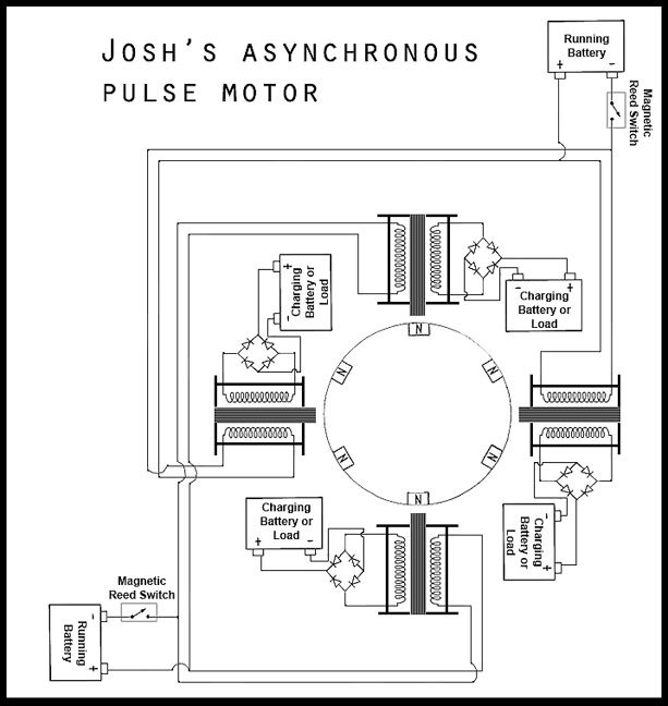
i was wondering... See the image, what if we added more coils where arrows are pointing (well even anywhere around the wheel)? wont it generate more electricity?

P.S. im not rly into electronics or physics so bear with me plz.. i just have lots of ideas flowing and figured i should ask ;]
P.S. im not rly into electronics or physics so bear with me plz.. i just have lots of ideas flowing and figured i should ask ;]


")
 , every time I run new experiment.


Comment