 Tweet
Tweet
Originally posted by lamare
View Post
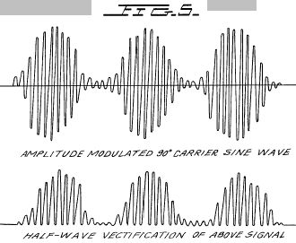
When yo say riding on top of a carrier wave, does this not imply AM modulation? In so doing where are you doing the modulation? In a normal AM transmitter the modulation controls the carrier amplitude and as such the modulator is a separate circuit from the carrier generation and is configured in such a way that the amplitude of the modulation controls the carrier output, so 100% modulation would vary from 0 carrier to 2X carrier. Now if you are talking more towards DSB, then we have a balanced filter that rejects the carrier and only passed the sidebands.
Where you speak of inserting a cap in series with a coil you also are creating a series resonant circuit where the primary frequency is suppressed and the sidebands pass. (Generalized idea)
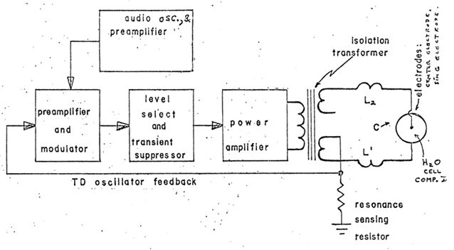
I know you know this, yet you explanation is as confusing to say the least, for us old fellows a simple hand drawn schematic would be great, we can feed the data into the computer and make the needed calculation to follow what you state you want to obtain, humm...
The diagram of Meyer and the rest of course are junk, so what is in your mind, idea sounds great, but we can't wrap around the circuit to match the idea.


Comment