Announcement

Collapse
No announcement yet.

Gray Tube Replication

Collapse
X
 
  • Filter
  • Time
  • Show
Clear All
new posts

  • This makes you wonder what capacitor 38 is for:

    Edwin V. Gray: Electromagnetic Association Motor (Pulsed Capacitance Discharge Motor, &c: US Patent # 3,890,548 )


    The patent claims:
    Upon cessation of the energy pulse (arc) within the conversion switching element tube the inductive load is decoupled, allowing the electromagnetic field about the inductive load to collapse. The collapse of this energy field induces within the inductive load a counter EMF. This counter EMF creates a high positive potential across a second capacitor 38 which, in turn, is induced into the second energy storage device or battery 40 as a charging current. The amount of charging current available to the battery 40 is dependent upon the initial conditions within the circuit at the time of discharge within the conversion switching element tube and the amount of mechanical energy consumed by the work load.
    This sounds like rubbish to me, because the other terminal of the coil is practically open, unless the safety spark gap fires.

    If we speculate that may be Gray got his hands on some earlier designs, like from Tesla, and we remember that in the old days electrolytic capacitors were built much like car batteries with a considerable distance between the actual plates, it is possible that indeed an old school electrolytic capacitor does give you a suitable delay line, while a modern, compact one does not. So, it is possible that the batteries were an addition in the zeventies to an earlier design from somewhere else, because the electrolytic capacitors at that time had considerably different properties than the ones from the thirties in terms of plate distance and therefore delay line properties...

    Update: and also gives us an interesting link to the Meyer/Puharich WFC systems, which also have a considerable plate distance, hence a delay line for currents to occur...
    Last edited by lamare; 12-27-2010, 10:02 PM.

    Comment


    • Thinking this further trough, I don't think the propagation speed of the EM field trough water makes much of a delay for the field. The EM propagation speed is about 9 times slower in water in comparison to air / vacuum, so even a water layer of 1 cm between the capacitor plates would not give any significant delay in the propagation of the field.

      However, with the CSET, we are rapidly discharging a cap trough a spark gap, where the long rod, which is at the potential of the discharging cap, very rapidly goes from a high voltage to zero. This long rod is capacitively coupled with the grid and connected to one terminal of the coil, while the other terminal of the coil is connected to a device that depends on slow moving ions as charge carriers, which need some time to react to an applied electric field. So, there is a delay between the moment a field, a voltage, is applied and the moment a matter based current starts flowing.

      Now the interesting thing is that it is not only currents that can cause a magnetic field:

      Maxwell's equations - Wikipedia, the free encyclopedia
      Ampère's law with Maxwell's correction states that magnetic fields can be generated in two ways: by electrical current (this was the original "Ampère's law") and by changing electric fields (this was "Maxwell's correction").

      Maxwell's correction to Ampère's law is particularly important: It means that a changing magnetic field creates an electric field, and a changing electric field creates a magnetic field. Therefore, these equations allow self-sustaining "electromagnetic waves" to travel through empty space (see electromagnetic wave equation).
      This suggests it is very likelly possible to create a magnetic field inside a coil using only a changing electric field, without having to provide any current to the coil in order to get the magnetic field.

      Interestingly, Bedini uses the same principle the other way around. He energizes a coil trough a transistor and then suddenly switches the transistor off, so no current can flow trough the transistor anymore. He redirects the sharp rising voltage at the coil terminal trough a diode to a charging battery. And then you get a DC spike, exactly because the ion based current inside the battery takes some time to react.

      That suggests that you can steer a CSET like capacitor, the long rod and the grid without the spark gap, from a Bedini motor by connecting the rod in between the coil and the diode to the charging battery, or between the diode and the charging battery. Then, you could connect a second coil in between the grid and the positive terminal of a second charging battery, while the negative of the battery goes to ground.

      If all this is correct, that should give interesting results...
      Last edited by lamare; 12-27-2010, 10:05 PM.

      Comment


      • It seems MUCH simpler to me. The capacitor 38 is charged through the coupling between the arc and the grid. While the capacitor is charging, a magnetic field is forming in the load coil. When the arc is broken, the coupling between it and the grid all but disappears (especially if the voltage field between the grid and the arc is only the voltage of the battery). The grid becomes a 1 terminal capacitor, multiplying its voltage, at the same moment the load coil experiences flyback, so everything is working together. This is the exact same effect used in Joseph Hiddink's patent
        Joseph Hiddink: One-Terminal Capacitor -- Articles & USP#4095162
        Last edited by SuperCaviTationIstic; 12-27-2010, 10:19 PM. Reason: added link

        Comment


        • Originally posted by SuperCaviTationIstic View Post
          It seems MUCH simpler to me. The capacitor 38 is charged through the coupling between the arc and the grid. While the capacitor is charging, a magnetic field is forming in the load coil. When the arc is broken, the coupling between it and the grid all but disappears (especially if the voltage field between the grid and the arc is only the voltage of the battery). The grid becomes a 1 terminal capacitor, multiplying its voltage, at the same moment the load coil experiences flyback, so everything is working together. This is the exact same effect used in Joseph Hiddink's patent
          Joseph Hiddink: One-Terminal Capacitor -- Articles & USP#4095162
          How does that explain the need for the batteries to be present, as Mark McKay said? :

          Originally posted by Spokane1 View Post
          There is meaningful observation documented where the non-classical output was a simple, but huge, DC spike that recharged the storage capacitor(s) and was also directed towards the storage batteries. The batteries were destroyed by this input -BUT they could not be eleminated from the circuit. Their circuit parameters were a requirment for non-classical operation. The motor could never run "closed loop" becasue the energy that was not extracted in the form of torque couldn't be effectively stored. They only needed a 60A alternator to top off the batteries from a functional standpoint. But if the motor ran for more than 30-60 minutes the batteries were toasted. If the motor was ran longer than this they exploded from hydrogen outgassing. Today this challenge might be solved with some huge carbon foam capacitors and sophiscated switch-mode power supply circuits.

          Comment


          • the batteries are there for the power supply to run the high voltage side, and as a direct source to charge the grid and cap 38. It's just a simple way to build a self contained system. And also, it's VERY dangerous to charge the grid/load/cap higher than the low voltage that the battery provides because of the resulting increase of voltage, and the cap/coil will explode or short out from arcing if the result is too impressive.

            If you read Hiddink's account of his experimenting, I believe he states that he charged it(what would be effectively the grid) to 6000 volts, and the result was about a 150kv impulse. The second time he charged 3 up and estimated over 500kv. The impulse was so strong that lightning touched down out of the blue sky.

            This is simple. This is real.

            EDIT: I'm now believe that Stan Meyer did the same thing, using the water as the load. Picture that explosive pulse that the gray tube makes going through water. Also, it is the EXACT same principle that a simple open air nitrogen laser uses, but the geometry is different. The gray tube is nothing more than a RADIAL open air laser.

            EDIT 2: Look at this simple diagram of a TEA laser. Nitrogen TEA laser - HvWiki
            forget about the way it switches for a moment (because this design is constantly running and not fired one shot at a time). If the left or right top plate were the outer grid, and the lower plate and the other top one were the rods, you have yourself a gray tube.
            Last edited by SuperCaviTationIstic; 12-28-2010, 12:42 AM.

            Comment


            • The following capacitive discharge system, while surely it must indeed
              produce substantial magnetic repulsion in coils 27 & 28, does not seem
              as interesting as having the diode there to react to a high voltage signal
              and redirect it into emitting from the spark gap onto a pickup grid.


              Does anyone have a clue as to how these two systems compare, as a matter
              of performance?

              One of my previous circuit illustrations modified to include a second
              pulsing circuit. It is the only logical solution I can think of as to
              why the output of the coil would not even be a fraction of the 70 or so
              volts going into it. The top value I've attained with nearly the entire
              range of the 555 - 386 chip combination circuit is around 3500V with this
              particular ignition coil, the reason it would be nice to utilize the
              secondary wall transformer I've attained.

              Comment


              • Originally posted by geotron View Post
                The following capacitive discharge system, while surely it must indeed
                produce substantial magnetic repulsion in coils 27 & 28, does not seem
                as interesting as having the diode there to react to a high voltage signal
                and redirect it into emitting from the spark gap onto a pickup grid.


                Does anyone have a clue as to how these two systems compare, as a matter
                of performance?
                As far as I can tell, the operation principle of this system is a dual classic Duddel/Poulsen like spark gap oscillator circuit, known as an arc converter circuit, around cap 25, the spark gap and the coil, with the coils 23/24 acting as higher frequency chokes. [There is a difference between what used te be known as a spark gap oscillator and an arc converter: http://www.energeticforum.com/122556-post2116.html ]

                There are two problems with this circuit:

                1. You need a considerable DC bias current trough your spark gap in order to get it into the required negative resistance region of operation, which likely costs you a considerable amount of energy that is wasted.

                2. There are two independent oscillation circuits that are never exactly equal. Even if they are fired at the same time, there will be slight difference in oscillation frequency, but how it is described in the patent, they are fired once the capacitor is sufficiently charged to break the spark gap, which is almost guaranteed to be not at exactly the same time...

                In the fuelless engine plans :
                http://www.tuks.nl/pdf/Reference_Mat...2050-350Hp.pdf

                They appear to use one spark gap across multiple coils in series, fired trough a reed switch, which probably solves problem 2.

                However, problem 1 remains, but if done right, it may very well be that the resonating coils pick up enough energy from the vacuum trough the electric field that the energy loss in the spark gap is made up for.

                Now I know there are a lot of question marks around the business methods of the guy who made these fueless engine plans, but Gary Magratten also claims to have built a working prototype along these principles:
                Pulsed Electromagnetic Motor by G.M. -- Prototype 2

                Magratten also has a nice picture of the negative resistance behavior of a spark gap:

                Additional Research material supplied by Gary Magratten


                To summarize: the variations of patent 3,890,548 appear to work using a classic arc converter to get the coils into resonance.

                It appears that the variations with the CSET does not use the spark gap's negative resistance region in order to get the coil into resonance. It appears it uses the spark gap to rapidly discharge the high voltage capacitor and use the sharp voltage decrease, the spike, to energize the coil trough a capacitive coupling between the long rod and the grid. In that case, according to Mark McKay, you need a battery in the system for "non classic behavior", which I think is needed to get a delay line for currents to occur.

                So, to answer your question: if the CSET variant works as I think it does and you only need a sharp spike in the shape of an electric field but no current per se to energize your coil, that could get you a significant better performance.
                Last edited by lamare; 01-04-2013, 09:42 AM. Reason: moved img to my own server

                Comment


                • Some interesting details about the history of Grays stuff:

                  http://www.free-energy-info.co.uk/Chapter5.pdf

                  In 1957, a Russian immigrant to the USA, one Alexei Poppoff, showed Edwin Gray a circuit which he said that he had been shown by Nikola Tesla. Edwin Gray did not understand the circuit and had no idea how to create anything useful based on it. He then joined up with his next-door neighbour Marvin Cole, who held a Masters degree in Mechanical Engineering and who, unlike Gray, was able to understand the circuitry.

                  In 1958, Ed Gray (shown above) left the Los Angles area in a hurry.

                  From 1958 to 1967 Marvin Cole, working alone, designed and built ever more powerful prototype engines, and it was a small one of these which was tested by Cal-Tech. In this period, Marvin also developed ever more powerful power supplies, which are the really important item in all of this. In 1967, Ed Gray rejoins Marvin Cole and together from 1967 to 1972 they solicited venture capital and promoted the technology.

                  Early in 1972, Marvin Cole disappeared and never saw Gray again. It is not clear if he was intimidated, died, or just did not want to be involved in all the publicity and effort needed to turn the prototype engines into a commercial product. No matter what the reason, the result was that Edwin Gray was suddenly disconnected from the brains behind the project, and that left him in a very difficult position. He didn't want to let go of the dream of becoming rich through this spectacular development, and so he tried to continue the development on his own.

                  As already mentioned, in May of the following year (1973), Gray had a small Marvin Cole motor independently third-party tested at the famous Cal-Tech laboratory in Los Angles, where a measured input of just 27 watts produced a measured output of 10 horsepower (7460 watts). The objective was to provide solid evidence of a new technology which was capable of changing the world and so would attract investors. To further boost his image and convince potential investors, in that same year of 1973, Edwin staged demonstrations which jumped electromagnets up into the air, showing the strength of the power which drove the Marvin Cole engines.

                  It is very important to understand that all of Edwin Gray's patents were applied for after the departure of Marvin Cole. These do not disclose the technology tested by Cal-Tech and it must be understood that Edwin was very much afraid of revealing anything important in any of the patents in case some other person would understand the things which were a mystery to him and snatch away the prize of commercial success. So, please be aware that the patents where applied for solely to encourage investors and most definitely not to show any significant details.

                  Edwin then assembled a small team of people to attempt to understand and advance the work of Marvin Cole. However, the subsequent changes to the Cole implementations did not result in genuine, reliable working motors due to Gray's lack of understanding of the underlying energy-tapping methods used by Cole.

                  The Power Tube shown in Gray's patents has never been shown to provide the COP=100 energy performance which is sometimes mentioned, nor did it form part of Marvin Cole's system. In 1976, Edwin Gray shows three of these Power Tubes driving one (failed version) motor. This technique is in direct conflict with Marvin Cole's successful technique which had 24 separate power supplies driving the motor. Please understand that the power-gathering mechanism of the Cole system is the key feature of all of the successful systems. Unfortunately, as far as I am aware, that technology has never been disclosed.
                  So, according to Patrick J. Kelly Grays technology did originate with Nikola Tesla, which we can speculate may have been the plans for Tesla's famous Electric Pierce Arrow:

                  Tesla's Electric Car
                  The "energy receiver" (gravitational energy converter) had been built by Tesla himself. The dimensions of the converter housing were approximately 60 x 25 x 15cm. It was installed in front of the dashboard. Among other things, the converter contained 12 vacuum tubes, of which three were of the 70-L-7 type. A heavy antenna approximately 1.8 meters long, came out of the converter. This antenna apparently had the same function as that on the Moray converter (see chapter on Radiant Energy). Furthermore, two thick rods protruded approximately 10cm from the converter housing.
                  70L7, Tube 70L7; Röhre 70L7 (70L7)
                  Tube: HalfWave Rectifier
                  Type: BeamPowerTetrode
                  So, there were 9 other kinds of vacuum tubes in Tesla's system.
                  More here:
                  Tesla Electric Car #1 - 01/09/98

                  At the appointed time, Nikola Tesla arrived from New York City and inspected the Pierce-Arrow automobile. He then went to a local radio store and purchased a handful of tubes (12), wires and assorted resistors. A box measuring 24 inches long, 12 inches wide and 6 inches high was assembled housing the circuit. The box was placed on the front seat and had its wires connected to the air-cooled, brushless motor. Two rods 1/4" in diameter stuck out of the box about 3" in length.

                  Mr. Tesla got into the driver's seat, pushed the two rods in and stated, "We now have power". He put the car into gear and it moved forward! This vehicle, powered by an A.C. motor, was driven to speeds of 90 m.p.h. and performed better than any internal combustion engine of its day! One week was spent testing the vehicle. Several newspapers in Buffalo reported this test. When asked where the power came from, Tesla replied, "From the ethers all around us". Several people suggested that Tesla was mad and somehow in league with sinister forces of the universe. He became incensed, removed his mysterious box from the vehicle and returned to his laboratory in New York City. His secret died with him!
                  So, the big question is: Did the first prototypes made by Marvin Cole use a CSET or not? Kelly says not, but is he correct?

                  Comment


                  • ..........................
                    Last edited by geotron; 12-29-2010, 09:07 AM.

                    Comment


                    • Originally posted by SuperCaviTationIstic View Post
                      It seems MUCH simpler to me. The capacitor 38 is charged through the coupling between the arc and the grid. While the capacitor is charging, a magnetic field is forming in the load coil. When the arc is broken, the coupling between it and the grid all but disappears (especially if the voltage field between the grid and the arc is only the voltage of the battery). The grid becomes a 1 terminal capacitor, multiplying its voltage, at the same moment the load coil experiences flyback, so everything is working together. This is the exact same effect used in Joseph Hiddink's patent
                      Joseph Hiddink: One-Terminal Capacitor -- Articles & USP#4095162
                      You do have a strange notion of SIMPLE, if I may say so

                      The abstract of Hiddinks stuff from your link:
                      "The invention provides a capacity changer comprising at least one evacuated glass tube having an ionizable gas disposed therewithin and a pair of mutually spaced electrodes disposed within the glass tube and selectively connectable through a switch to a first power supply, the gas, when ionized, acting as a first capacitor electrode. A conductive coating on the outside of the or each glass tube forms a second capacitor electrode capacitively coupled to the first capacitor electrode when the gas is ionized, the first and second capacitor electrodes thereby forming a two-terminal capacitor. A second power supply is selectively connectable through a further switch between the second capacitor electrode and the first capacitor electrode when the gas is ionized, the second capacitor electrode further forming at least part of a 1- terminal capacitor when the gas is not ionized. The two-terminal capacitor formed by the ionized gas and the second capacitor electrode may be charged and then, when charged, converted into a one-terminal capacitor formed by the second capacitor electrode. In this way, very high voltages may be attained".
                      An intrigueing idea, he may be up to something, but I doubt if this is what happens in the Gray tube.

                      First of all, you talk about a coupling between the arc and the grid. The arc is formed between the two rods and basically is a low resistance current path between the electrodes of the arc, in between which you have a strong electric field. So, any ions and electrons that are formed in between the electrodes should move between the electrodes of the arc and not float away into the space surrounding the arc. So, I don't see any reason to assume charge carriers moving from the rods towards the grids, as many have assumed. All I see is a capacitance between the long rod and the grid, which I have measured to be in the order of 10 pF in my replication. If the grid surrounds the short rod also, there is a capacitance there too, which is smaller, may be in the order of 1 pF. So, to me, the most simple explanation for any coupling of the grid with the components surrounding the arc is this capacitive coupling which we know is there.

                      Secondly, you suppose capacitor 38 to be charged trough the inductor, while it is well known that an inductor acts as a HF choke, it blocks high frequencies, while it is frequently stated that the phenomena associated with Gray's system involve fast switching, so high frequencies. And beside that, the current would have to flow trough the capacitive coupling between the rod and the grid, which will not give you much current, because it is such a small capacitance.

                      So, I don't think this explains it.

                      Comment


                      • How kind you have been helping all of us with this. Many thanks lamare!

                        Tesla could have utilized a vacuum tube with the antenna on his car
                        to amplify the radiant space energy being collected into it. TH Moray
                        had a similar method of collecting energy from the vacuum. pg-9

                        Aaron, I am seeing now most of the things that have been confusing me, although
                        in your following illustration there is something that remains a mystery.

                        In some videos and images I've seen the use of polarized electrolytic capacitors,
                        while you have clearly included non-polarized banks C1 & C2 for unidirectional
                        flow. This tells me that I will have to build or obtain new ones that would allow
                        this, with my current stock of those designed to only flow one way.

                        My graphical interpretation is below - as can be seen I have included a second
                        spark gap to give distance between them, while uncertain whether or not this is
                        truly acceptable or not.


                        Comment


                        • Originally posted by SuperCaviTationIstic View Post
                          the batteries are there for the power supply to run the high voltage side, and as a direct source to charge the grid and cap 38. It's just a simple way to build a self contained system. And also, it's VERY dangerous to charge the grid/load/cap higher than the low voltage that the battery provides because of the resulting increase of voltage, and the cap/coil will explode or short out from arcing if the result is too impressive.
                          You seem to miss the essence of what Mark McKay is saying in the part I quoted above. He says the batteries are essential for "non-classic operation" and that this is a documented observation. To me, this is one of the most important clues I have read ever since I started studying Grays stuff. And since this comes from McKay, one of the most knowledgeable persons on the history of Grays stuff, I have no doubt this is accurate. And beside that, John Bedini has also stated the importance of batteries in his systems. "It's in the batteries!", is what I recall hearing him say on one of his video's.

                          So, whatever you may think of my theoretic explanations, you can count the batteries being important for getting "non-classical" effects as being a fact.

                          I think this is because ions, which are the charge carriers inside batteries as well as electrolytic capacitors, are slow moving and therefore need some time to react. However, the fields that are the actual cause for currents to occur travel with the speed of light. So, because of the slow reacting ions, you have a certain period of time during which there is an applied electric field, but not yet any current flowing trough the battery. And according to the well known Maxwell equations, a changing electric field, radiant energy in Bedini's words, is perfectly capable of giving you a magnetic field on it's own:

                          Maxwell's equations - Wikipedia, the free encyclopedia
                          Ampère's law with Maxwell's correction states that magnetic fields can be generated in two ways: by electrical current (this was the original "Ampère's law") and by changing electric fields (this was "Maxwell's correction").

                          Maxwell's correction to Ampère's law is particularly important: It means that a changing magnetic field creates an electric field, and a changing electric field creates a magnetic field. Therefore, these equations allow self-sustaining "electromagnetic waves" to travel through empty space (see electromagnetic wave equation).
                          So, it is a fact batteries are important for the operation and it is also a fact that a changing electric field can cause a magnetic field. And even though it is well known that the electric field can cause a magnetic field, this is normally not taken into account when talking about coils, because normally currents start flowing trough the coil immediately, so the effects caused by the field itself can be neglected.

                          And since it appears that Gray got his ideas from Tesla and old school electrolytic capacitors were constructed much like car batteries, with a considerable plate distance, one can speculate that capacitor 38 is supposed to be an old school electrolytic capacitor and that modern ones are less suitable for obtaining the non classical effects we are after, which is why Gray needed a battery in his circuit in order to get the non classical effects.
                          Last edited by lamare; 12-29-2010, 09:53 AM.

                          Comment


                          • Originally posted by SuperCaviTationIstic View Post
                            EDIT: I'm now believe that Stan Meyer did the same thing, using the water as the load. Picture that explosive pulse that the gray tube makes going through water. Also, it is the EXACT same principle that a simple open air nitrogen laser uses, but the geometry is different. The gray tube is nothing more than a RADIAL open air laser.
                            There definately is a link there, as well as with Bedini and Puharich. Puharich may have been the origin of Meyer, since he referenced one of Puharichs patents in one of his patents, but that may also have been done by the patent examiner.

                            Anyway, it is now clear that all of them, including the earlier Marvin Cole versions of Gray as far as I can tell, discharged a coil into a device containing metal plates with a water solution in between, either a battery, an electrolytic capacitor or a WFC. The WFCs as built by Meyer was also an electrolytic capacitor with some form of dielectric layer on at least one of the tubes, either by some form of conditioning process, or the natural dielectric layer on stainless steel that normally protects the steel from rusting. For all these systems, hydrogen production has been reported, a desired feature for Meyer and Puharich but a problem for Gray.

                            So, one can speculate that if indeed Gray got his hands on some earlier Tesla plans, which included this strange tube device, Gray concluded that must have been the holy grail and guarded the CSET as his secret. I think it is likely that Marvin Cole constructed the first prototypes along the lines of the later patents, while they thought the CSET was the holy grail. It worked, but they got major problems with the batteries.

                            So, Cole left the scene for one reason or another, and Hackenberger continued. It seems they looked into the old school Duddel/Poulsen arc converter circuits and built the newer models using arc converter oscillators, which got rid of the problems with the batteries, but also ruined the performance, since the batteries are a key element for the non classical process as Mark reported.

                            So, it may be they eventually patented the CSET design because on the one hand it was necessary for the circuit to operate, while on the other hand they ware unable to get it working reliably, because of the problems with the batteries, so their only hope was that someone else solved the problems, so they could cash in on the patent.


                            One other thing. If the CSET relies on sharp rising/falling voltages on the long rod in order to get a large dE/dt to create a magnetic field inside your coil, you don't want a big capacitor to discharge trough your CSET. There are some numbers available about the power consumption of what I think was the Cole prototype:
                            Edwin V. Gray: Electromagnetic Association Motor (Pulsed Capacitance Discharge Motor, &c: US Patent # 3,890,548 )
                            The EMA motor was operated into a 10 HP dynamometer load at 1100 rpm. This power output is 7460 watts. The total battery power available from the four batteries was 5454 watts for one hour. The total battery power consumed by the motor during a 21-minute run was only 9.75 watts; this equals 26.8 watts per hour
                            Evolution of the E.V. Gray Circuit Topology -- by Mark McKay
                            The Hackenburger Technical Discussion2 discloses a possible switching power supply frequency of 360K CPM or 6 KHz and an operating voltage of 3000VDC. This is a reasonable speed for a DC-DC instrument chopper at the time, but a rather low frequency by today’s switch-mode power supply standards7. The operating voltage is also consistent with the Jack Scagnetti Article3 (1973).
                            If we can assume a working system with a CSET to consume about 27 Watts at 6 kHZ, we can make an estimate of the size of the capacitor which is being discharged trough the CSET, since the energy stored in a capacitor, U, equals 1/2 C V^2, so C = 2 U / V^2.
                            When we take U to be 27/6e3 and we take V to be 3 kV, we can calculate C = 2*27/(6e3 * 3e3^2] = 54/54e9 = 1 nF.

                            So, the cap needs to be something in the order of about 1 nF, not something in the range of uF for the proper operation of the CSET.

                            This appears to be confirmed by some very interesting info by earlier experimenters here:
                            www.free-energy-info.co.uk/MKay5.pdf

                            (Tad Johnson) The frequency is adjustable to a degree through adjustment of the spark gap distance and cap size. The caps I am using are 500pF so frequency should be in the KHz range depending on how much amperage the power supply is charging the stack with. Just got the HV resistors today. All I have left to do is build the CSET and figure out the charging circuit. Hydrogen or magnetically quenched gap on the output might be added later for even higher frequency and more protection against current reversals.

                            [...]

                            (Tad Johnson) Interesting findings after running the Gray circuit for a couple hours:
                            ERE does NOT manifest if there is no resistor on the spark gap end of the CSET. Repeat ZERO POWER if no resistor in place. The more resistance, the more the effect appears to manifest.
                            With 300 Ohm or more of resistance the grid starts to put off a FRIGHTENING amount of power.
                            Enough to smoke a 50watt, 500 ohm resistor in less than 30 seconds. My input was 12 watts total from the wall. Output from the CSET grid is UNMEASURABLE. Grounding is also becoming an issue since I cannot run the end of the CSET back to ground with a resistor in between. Also, the energy coming off the grid appears to be harmful even with fast rise and fall times contrary to other information out there.
                            Anyone have any bright ideas on measuring this high amperage, high voltage energy I would be very happy. We need accurate wattage out at this point. I feel confident already with my input measurements.
                            Last edited by lamare; 12-29-2010, 03:25 PM. Reason: typo in cap calculation

                            Comment


                            • gray circuit comments

                              Originally posted by geotron View Post
                              Aaron, I am seeing now most of the things that have been confusing me, although
                              in your following illustration there is something that remains a mystery.

                              In some videos and images I've seen the use of polarized electrolytic capacitors,
                              while you have clearly included non-polarized banks C1 & C2 for unidirectional
                              flow. This tells me that I will have to build or obtain new ones that would allow
                              this, with my current stock of those designed to only flow one way.

                              My graphical interpretation is below - as can be seen I have included a second
                              spark gap to give distance between them, while uncertain whether or not this is
                              truly acceptable or not.


                              Geotron,

                              Actually, I am using polarized electrolytic capacitors for the LV cap banks.

                              That diagram is a bit tricky as c2 is charged from the HV and when at a
                              high enough voltage, causes the effect when HV hits it - again only when
                              the c2 is charged from the HV. The inductor doesn't interefere with HV
                              potential blasting thru it to charge c2.

                              Anyway, c1 is even optional as well.

                              If you have a capacitive discharge ignition as the HV and discharge
                              that across a gap into c2, which is charged from a separate power
                              source, you will get the effect. I'd just make the point going to ground
                              closer to C2 than to C1 so c1 (CDI) is forced to hit C2 before going to
                              ground.

                              The inductor, I'd move it to the line going to ground. It works in either
                              place though.
                              Sincerely,
                              Aaron Murakami

                              Books & Videos https://emediapress.com
                              Conference http://energyscienceconference.com
                              RPX & MWO http://vril.io

                              Comment


                              • Originally posted by Aaron View Post

                                Actually, I am using polarized electrolytic capacitors for the LV cap banks.
                                And you have it in series with the coil....

                                If indeed the ions inside an electrolytic cap cause a delay for currents to flow, then you have the essence of what Gray was doing. A HV sudden discharge into a coil causing a magnetic field because of the changing electric field during a short moment where there is not yet a current flowing, which is possible because the other terminal is loaded with some device containing an electrolyte fluid in between metal plates: an electrolytic cap, a battery or a WFC.


                                Update: If it is correct that the excess energy effects are due to the combination of a coil and an electrolytic cap, it should also be possible to get an excess energy effect by using one spark gap and putting the whole train in series: HV Cap - spark gap - diode - switch - coil - LV Cap. If you take a relay for the switch, you should be able to pulse-charge the LV Cap using very little current from the source and gain energy which is tapped from the changing electric field being converted to a magnetic field in the coil during the brief moment the electrolytic cap needs for a current to get flowing.

                                This may be worth a try, because with this experiment, we can determine whether or not the excess energy effects are caused by a delay trough the LV electrolytic cap, or by mixing of the HV and LV discharge trough the spark-gap.

                                Update 2: Oops, that won't work to charge a cap. There is no path for the charge to flow from one plate of the cap to the other So, everything put in series would just create a series oscillation circuit with the coil and LV Cap, which would just ring for a while and dissipate all energy.
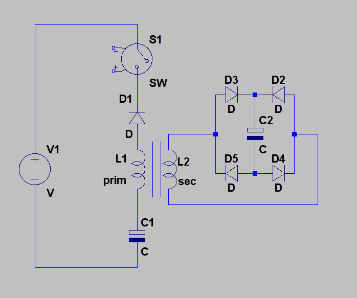
                                However, if you would take the primary of a transformer instead of a single coil, you could a diode bridge at the secondary and use that to pulse charge a third cap.

                                Update 3: See attached schematic for the idea. In this one, the switch acts as spark gap at the same time. When the switch closes, at some point you get an arc across the contacts, which should give you a sudden change in the electric field around the coil, even before any current can flow, which should give rise to a magnetic field in the coil, in proportion with the sudenness of the rise time of the voltage (see Maxwell, dE/dt). This magnetic field is then used at the secondary of the transformer to charge C2. C1 has no other purpose but to delay the moment a current starts flowing trough the coil and should be an electrolytic cap. Of course, V1 would be a high voltage source.

                                Update 4: here's a high res version of the schematic:
                                Attached Files
                                Last edited by lamare; 12-31-2010, 08:54 AM.

                                Comment

                                Working...
                                X