Announcement

Collapse
No announcement yet.

Gray Tube Replication

Collapse
X
 
  • Filter
  • Time
  • Show
Clear All
new posts

  • yes this is why a 10 turn coil is required on each side of the circuit. stationary waves and reflections play a part. Tesla's circuits were all about stationary waves and the reflections (Tesla's zinc box) amplify it


    Tesla presumably got the idea of reflections from hertz's work with zinc sheet on a wall in his experiments
    Comment


    • Historical Facts about E.V.Gray's technical contribution

      Originally posted by antigraviticsystems1 View Post
      Decoding Gray's Patents
      significance might be. Also, Gray claims that
      he uses only a positive form of energy.

      Therefore, everything Gray said makes sense.

      Gray must have figured out that he could create an electronic charge on his
      receiving grids if he intercepted the Electro-Radiant Event on copper.

      But in Gray's smaller system, this was just what he needed. The more
      the Electro-Radiant energy interacts with copper again, the sooner it returns to a form of electricity that will actually charge the battery in a fairly normal way. This then is how Edwin Gray produced cold electricity.

      To summarize, Gray's cold electricity circuit runs like this:

      Gray could keep the system going indefinitely, and still produce a sizable
      output.
      Dear antigraviticsystems1,

      Your discussion about the proposed function of the E.V. Gray technology is what good speculative dialog is all about.

      However, please keep some historical perspective in this matter about crediting E.V.Gray with all these observations, discoveries, and technical solutions.

      1. E.V. Gray DID NOT DISCOVER OR DEVELOP THIS TECHNOLOGY

      2. E.V. Gray was an auto-body fender man who was a salesman and promoter of this technology.

      3. E.V.Gray never did learn Ohms law or any other basic electronic relationship about electromagnetics or electrostatics. His alledged attendence in military technical schools was a complete fabrication.

      4. E.V. Gray never understood nor could build a complete Free Energy Engine, however he probably did have an partial understanding of about 75% of what was in one.

      5. E.V. Gray did not compose the Pulse Engine patent. In fact he probably didn't contribute a single sentence to the document. The patent was written by Dr. Norm Chalfin - for a fee, based upon existing drawings and limited observations of the EMA4 engine.

      The E.V.Gray technology is still valid and PFM, but it is incorrect to present a technical argument about Gray doing this or Gray doing that when in fact Mr. Gray did nothing to advance the technical develompent of this marvelous discovery.

      Mark McKay, PE - E.V. Gray Historian
      Last edited by Spokane1; 08-10-2011, 04:25 PM. Reason: Wrong Person

      Comment


      • Update 42 - Edwin Gray Tesla / disruptive discharge hybrid circuit - paralleled thyratrons - YouTube

        ok i have setup my circuit to be almost 100% the same as grays patent. I am now running thyratrons in parallel (control grid powered by 10-20 VAC) and it appears to be running more reliable. I got this idea from the youtube video entitled gray motor found.

        Also finally got diode 46 into the circuit. I now believe this is quite important.

        I am now seeing the beginnings of battery charging

        The next step for me is to now replace the run batteries with higher amp hour rated batteries.

        Comment


        • Comment


          • geotron,

            not sure what you are trying to say...


            All,

            I am starting to suspect that the cap shorting (16) and the commutator (26) need to be syncronized. I will test this next. It sort of makes sense based on what i have seen so far. But i can't see how the thyratron will work when i test it. I guess we shall find out soon

            Comment


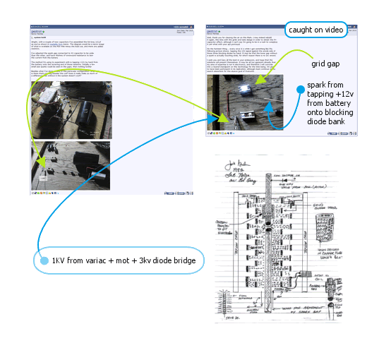
            • The purpose of my experiment was to demonstrate the results
              of operating the system as shown by Mr Bedini. The diagram
              I have included above is showing the two electrodes facing
              eachother with a gap, while there is a second gap onto the
              grids and a blocking diode on the low-voltage side.

              The gap onto the grids, in my case just a standard spark gap,
              leads to a 2KV cap and the other side of it connects to the anode
              of the diode bank.

              On the MOT charger is another 2KV cap, its cathode side connected
              onto the (-) battery post while the (+12v)bat is being tapped onto
              the anode of the diode bank.

              The results indicate potential success, even in such a primitive form.

              Forseeably this version of the Gray Tube system will now be more
              readily accepted as being a valid technology. It is my hope that
              others will confirm this and post their results, hopefully in a
              form more closely resembling the way it ought to be built.

              Performance figures remain unknown.

              Comment


              • Originally posted by Spokane1 View Post

                <snip>

                5. E.V. Gray did not compose the Pulse Engine patent. In fact he probably didn't contribute a single sentence to the document. The patent was written by Dr. Norm Chalfin - for a fee, based upon existing drawings and limited observations of the EMA4 engine.

                The E.V.Gray technology is still valid and PFM, but it is incorrect to present a technical argument about Gray doing this or Gray doing that when in fact Mr. Gray did nothing to advance the technical develompent of this marvelous discovery.

                Mark McKay, PE - E.V. Gray Historian
                If that is the case, then the Gray patents should not be considered to be describing the actual theory, but merely as giving a possible interpretation/theory of a working system.

                Based on Eric Dollard's work on the Tesla Coil and given that earlier Gray prototypes used no CSET but rotating spark gaps, I think the CSET is nothing but a triggering device, while around "spark gap protection device 42" you have a classic negative resistance spark gap discharge circuit, which produces "an extreme impulse of M.M.F. (magnetic force)" as Dollard describes.

                Since I think this same principle can be applied to Bedini motors using a lamda diode as negative resistance device, I created a separate thread for this idea:

                Gray's secret and its application to Bedini's motors.

                Any comments welcome, of course.

                Comment


                • Negative Resistance Considerations

                  Originally posted by lamare View Post
                  If that is the case, then the Gray patents should not be considered to be describing the actual theory, but merely as giving a possible interpretation/theory of a working system.
                  Dear lamare,

                  You are correct. The pulse engine patent was composed of many of the actual mechanical drawings used for the construction of the working EMA4 Free Energy Engine. But, like you say the theory of operation was just a shot in the dark made by a person who was never given the actual operational information. There is a lot of missing data in that patent document, especially in the schematics that were disclosed and certainly in many details of the power supply.

                  QUOTE=lamare;151781]
                  Based on Eric Dollard's work on the Tesla Coil and given that earlier Gray prototypes used no CSET but rotating spark gaps, I think the CSET is nothing but a triggering device, while around "spark gap protection device 42" you have a classic negative resistance spark gap discharge circuit, which produces "an extreme impulse of M.M.F. (magnetic force)" as Dollard describes. [/QUOTE]

                  I agree with you and your observation. I also think that is where the non-classical process takes place. The E.V.Gray technology exploits the process with a modified arc. The Bedini technology (from my observation) uses the negative resistance in his NPN switching transistor during secondary breakdown. Both conditions involve a matrix of positive ions being stressed with a sudden change in energy density.

                  If Eric Dollard observed this process as well - then I missed it in my reading of his work. I shall have to review your analysis of his efforts and see what he is talking about. Every little idea helps.

                  However, I think that overall the Gray technology was able to acheive huge COP's while the Bedini technology seems to yield low level and intermittant results.

                  QUOTE=lamare;151781]Since I think this same principle can be applied to Bedini motors using a lamda diode as negative resistance device, I created a separate thread for this idea: [/QUOTE]

                  No doubt that is a viable line of investagation. I hope that something becomes of it since it does relate well with the more powerful Gray technology.

                  Mark McKay

                  Comment


                  • I think that process required also inductance which is missing from Gray patent schematic. Because large capacitor was used inductance could be small and contained directly inside CSET tube near carbon rod or just motor coils were used as inductance.

                    Comment


                    • Gray Technology Inductance

                      Originally posted by boguslaw View Post
                      I think that process required also inductance which is missing from Gray patent schematic. Because large capacitor was used inductance could be small and contained directly inside CSET tube near carbon rod or just motor coils were used as inductance.
                      Dear boguslaw,

                      You are certainly right there. I have some audio recordings of Mr. Hackenberger talking with GD about the importance of the "Transformer". At the time he was convinced that this trnasformer was the heart of the non-classical oepration for both the rotary engines and the non-rotary electrostatic Generators. As you know these transformers were custom made by Mallory Electric Company, but Mr. Hackenberger thought they could be made by any transformer fabricator for a 20% premium. They were constructed much like an automotive ignition coil in that they had "open" cores and provisions for HV isolation on the secondary. I'm sure the primary was would on the outside.

                      If there is any correlation to this subject then the "Brown" Motor aka the "Gold Motor acquired by Al Francouer a few months ago has a transistor inverter power supply that came with it. This unit appears to be a 24VDC to 3000VDC regulated chopper. The transformer in this unit is unique since two HV power taps are provided with seperate HV bridge rectifiers. This circuit was built in the late 70's becasue of the components used. And who ever did it knew their way around quality prototype construction. Given the time line it seems that this was Mr. Hackenbergers work and this power supply was not originaly part of this motor series since it was missing from the 1986 family photo of motors. This might have been the power supply for the "Blue" Motor. The transformer is much more modern with a ferrite "E" core that could have a gap in it to limit potential magnetic saturation.

                      In my opinion the "inductance" used was a complex circuit and not a straight simple inductor. I suspect its overall purpose was to provide the right voltage-current profile to the arc to get it to do its thing. Just like Bedini has his trifilar open core coil designed to stress the switching transistor in the right way.

                      The Pulse engine patent is missing a lot of things, so there is nothing new in that department. I believe that the complex inductance used in the EMA4 was to be found in the "Major" and "Minor" electromagnets. These units are open core and they provide a variable inductance with rotation. We know that the "Major" electromagnet was at least a two coil transformer, probably wound as an auto transformer.

                      My WAG is that the combination of coils provided a 15 KV strike voltage for the initial arc. Once the arc was struck it was current regulated to allow for a continuous burn time on the order of 8 milliseconds. Getting all these parameters to work out is harder than it seems, but I'm still worlking on it.

                      Mark McKay

                      Comment


                      • Hi mark,

                        Do you know if al francouer is going to release any details on these motors/circuits?

                        Thanks
                        N.

                        Comment


                        • Originally posted by Spokane1 View Post

                          If Eric Dollard observed this process as well - then I missed it in my reading of his work. I shall have to review your analysis of his efforts and see what he is talking about. Every little idea helps.
                          Dear Mark,

                          Dollard writes about the production of extreme pulses of magnetic force using a negatice resistance device, in Eric Dollard's "Condensed Intro to Tesla Coils":

                          http://www.tuks.nl/pdf/Eric_Dollard_...Coils(OCR).pdf

                          The formation of the energy impulse involves the discharge of a capacitor with the highest practical stored energy into an impedance (inductive) of the lowest practical value, and the discharge path is coupled to an energy supply through a negative resistance device. This negative resistance is classically a spark discharge, but a superior plasma device needs to be developed to enhance efficiency. Under optimal conditions the exponent of oscillation amplitude will be positive over a sustained period of time.
                          The net result of this system is the production of an extreme impulse of M.M.F. (magnetic force).
                          This is how he describes what happens in the primary of his three-coil Tesla coil, which he uses to produce plasma effects. However, he used an extremely short primary air-core coil with a very low series resistance, while Gray probably used a coil with a (very) long and thin wire, which means the resonance frequency of Gray's coils is waaaay lower than Dollard's one. So, Gray's coils are more like Newmann's than Dollard's, but apparantly these show the same kind of effects:

                          JLN Labs - The Newmans's Machine Cooling effect
                          The following is prompted by a recent experimental observation by Jean-Louis Naudin of an anomalous cooling effect in a large coil of wire.

                          I would like throw out an idea to the members of this open forum to consider and comment on.

                          It came to me in an attempt to explain the cooling effect in a large coil of wire observed by the physicist Leon Dragone in an experiment he called the electroentropic device in 1989, as well as in his investigations of a Joseph Newman type electric motor. Sadly, his experiments were cut short by a heart condition that caused him to die at an early age.

                          Leon measured a temperature drop of up to 2 degrees F. (0.8 C) in a large coil of wire connected to his special cold cathode arc switch.

                          I met Leon Dragone at a conference hosted by the Planetary Association for Clean Energy in Canada. Leon and I immediately became friends as I stayed up all night talking to him about energy ideas at the conference.
                          We had very similar ideas about the possibility of organizing (or cohering) fluctuation energy such as thermal and quantum zero point fluctuation energy. Sadly, he died a few months later he died of a heart attack. He did not publish much information but I had many phone conversations with him in which he described his ideas and experiments.

                          At the conference Leon showed me and others, his "electroentropic device" which seemed to show an excess energy gain. It consisted of a Neon sign transformer secondary coil connected in series with a micrometer adjustable spark gap also in series with a light bulb and a 575 volt battery pack. The battery pack also had a 3.5 uFD 4000 volt capacitor connected in parallel across it. The spark gap device was a small black box with a micrometer adjustment knob and two wires sticking out. The wires were connected with alligator clips and small gauge wire.

                          When the spark gap was shorted, the bulb would not glow at all as only 25 milliamperes was flowing through it due to the 18000 ohms of resistance in the neon sign transformer. When Leon would carefully adjust the spark gap device the light would glow quite brightly and the current would increase to over 1000 milliamperes.

                          Leon told me that he would get the same effect with a Newman type coil connect instead of the Neon sign transformer. Leon told me and this was later confirmed by Dr. P.T. Pappas ( a physicist from Athens, Greece ) that when the spark gap was operating in "excess energy mode" they were able to measure a drop in temperature of the coil of about 2 degrees Fahrenheit or (0.8 Celsius). The spark gap was what they called cold cathode glow discharge spark.
                          Seems to me that "excess energy mode" == "negative resistance mode".


                          So, it looks like we have to dig up some old school literature about how to work with spark gaps.

                          What makes a negative resistance device so interesting for steering coils into resonance for applications in magnetic motors is that the current trough a practical negative resistance device, like a spark gap or lambda diode, is always positive! See for example the I-V curve of a typical lambda diode circuit:

                          Lambda diode


                          That means you can get a coil into a resonance mode where you have a superposition of a DC current and a complex AC wave going trough it, such that the magnetic field is directed into one direction. In other words: there are no areas in the coil where a reverse direction of the magnetic field occurs. So, this DC offset is very important for the application of resonating coils in attracting/repelling motors. What happens is that besides the normal DC current going trough the coil, generating a magnetic field, you get additional wave-like impulses going trough the coil, which travel at a much greater speed than electrons (DC current), and therefore generate an extremely powerful magnetic field inside the coil, which you can harnass using magnetic attraction/repelling in a motor as well as by capturing the BEMF when allowing the magnetic field to collapse.

                          Comment


                          • The Arc

                            Dear lamare,

                            What makes the Gray technology different from the researchers you mentioned is that the arc is dynamacaly stretched across the surface of a dielectric in the presense of an axel magnetic field. These additional factors probable make the differance between a COP of 1.5 and 275. No doubt it is being manipulated during its negative resistance mode.

                            The associated transformer has to be designed to strike the arc and then modify the current to maintain the negative resistance condition for as long as possible.

                            The next question is "so what happens then"? What ever OU is created in the arc has to be harvested and converted into real world work.

                            From my study of the Gray technology this "Whatever" was created and then stored in short sections of large coax delay lines. It was made in one part of the engines rotation and then used in the remaining portion. This "Whatever" was utilized just like classical electricity in that it was conducted through opposing electromagnets made of copper wire, however the torque created was several orders of magnitude greater than what classical electricity could produce and the coils got cold.

                            If this storage phase actually did take place back in 1973 then it appears that we are dealing with the creation of new kind of particle or energy carrier or something else that has a pretty long life.

                            This particle would be created in the negative resistance arc.

                            I'll study your references from Mr. Dollard in more detail and comment later.

                            Mark McKay

                            Comment


                            • Al Francouer's &quot;Gold&quot; Motor

                              Originally posted by nat1971a View Post
                              Hi mark,

                              Do you know if al francouer is going to release any details on these motors/circuits?

                              Thanks
                              N.
                              Dear nat1971a,

                              Normaly Al is quite generous with the information he has. However his present employment rith now is seasonal and involves long hours. Apparently he is now working as a Forest Fire Camp Manager. This is long hours away from home and way out in the boonies. But, I think it pays pretty good.

                              Just before his season started this year Peter Lindemann and I visited Al and took several photographs. Al had already transcribed the surviving wiring. I reproduced these sketches into AutoCAD. I would be happy to relsease this information but it is based on Al's work and is his property. So, to maintain professional form I will let him be the one to disclose what he wants to and when. I think his season is over with by the end of October.

                              Keep in mind that the "Gold" Motor was an early pulse motor (circa 1964) and not a Free Energy Engine - there is a big differance between the two technologies. The Free energy phenomena was discovered while developing these industrial Pulse Motors (five models), so the Free Energy Engines have their roots in this design. However in 1980 Nelson Schlaft rewired this motor so that it would run on Ignitrons and 5000 VDC. What is left are these modifications. How the original Pulse motor was wired and how the electromagnets were wound has been lost, darn. But, there is still some information to be observed from the mechanical construction of the remaining hardware.

                              The puzzling issue is the power supply box that came with the motor. This was built in the late '70's. Mr Schlaft did not have the technical expertise to construct such a device, nor did Gray have anyone in his emlpoy after 1980 who could do it either. Given the history, only Mr. Hackenberger could have done this. This power supply was not electrically connected to the rest of the equipment on the cart.

                              This power supply employed two early IC pulse width modulators for voltage regulation (possibably a positive and negative version since the part numbers are different). Since only one adjustable potentiometer is provided I would assume that the dual 3KV voltage outputs were ment to track each other. Mr. Hackenberger must have had more time than money to build this device. I would estimate it took at least 200 man-hours of construction and engineering time by someone who knew what they were doing. The need for this power supply must have been urgent. Had this unit been built when the money was coming in Gray would have had this circuit custom fabricated. The switching elements are a cluster of four large power NPN transistor with TO-3 cases. There are two clusters on massive heat sinks. Most of the worked was tied up in the con struction of the controller.

                              I suspect that Mr. Hackenberger was very short of money. This was the circumstance that he found himself in in 1978. However he was in ernest to get this technology running again and he knew how to do it. The professional power supplies that were built for the EMA6 for the 1976 show had been confiscated by the FCC. So he probably canabalized the existing power supply from the "Gold" pulse Motor and upgraded it to meet his needs. As a result the chassis still fits the hole on the Gold Motor cart, so that is where it ended up when Gray packed up and left town.

                              As time permits I shall attempt to wring out a little more information about this power supply, but it will be up to Al as to what he chooses to disclose.

                              mark McKay

                              Comment


                              • Thanks for the feedback mark.

                                I have acquired a dual pole relay to test my theory that the HV capacitor shorting and the commutator need to be syncronized. Will hopefully test it this weekend!!

                                Comment

                                Working...
                                X