Announcement

Collapse
No announcement yet.

Gray Tube Replication

Collapse
X
 
  • Filter
  • Time
  • Show
Clear All
new posts

  • Originally posted by kalena555 View Post
    Dear Mark,

    The bit of info of getting the motor to run without the tubes is new info to me. So much learn XD. Well now I'm gonna scale back my test setup a bit, I'm on limited funds (aren't we all) but I still will build it just to test it. It's an interesting device regardless and if nothing it will teach me a lot. My experienced in the FE is quite limited in terms of actually building circuits (joules thief mostly and working on a solid state state ssg type circuit). Theory is all well and good but until I start more projects I won't learn more so I'm diving head first into this XD
    Hello, dier Mark, kalena555 and all members this site!
    For you - about principles of work CEST of Edvin V. Gray:
    All wishing to receive the free energy:

    Free Energy can be obtained with a low cost electric energy only in microwave-active resonance of physical processes, when it haves an internal positive feedback with ether (physical vacuum). The dimensions of elementary particles, atoms, molecules and so forth, and a dimensions basic resonant connections is extremely small (as compared with the wave-length), but their number per unit volume is enormous. In such systems the total energy of radiation/absorption on active centers is determined by their concentration per unit of volume taking into account all kinds and forms of its interaction.
    The Hydrogen Generator microwave oscillation with internal positive feedback (MASER) works in the interstellar space and the energy converter Edwin gray (CEST) at a frequency of f = (1,420,405,701.800 ± 0.028) Hz. It described in Feynman's lectures on Physics: The entire set of lectures:
    Download Feynman_Lectures_on_Physics_Complete.pdf for free on Filesonic.com
    See Vol. 3, Lecture 12, pp. 12_1 – 12_12. (At the counter pages: the third volume begins with page 1050).

    Now see fig. 12-2; 12-3; 12-4:


    These Feynman's figures show, that in "neutral" atoms of hydrogen an energy of electrons with reverse spin (state of the II and IV) with increasing magnetic field strength DECREASES, but for the electrons with normal spin (state I and III) it INCREASES -as it should be in our World.

    Edwin Gray somehow reached the understanding, that in order to obtain free energy, should be somehow from the entire mass of the electrons of atoms of hydrogen in the neutral state, to separate the electrons with reverse spin, which are in a states II and IV (the state of a positrons).
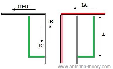
    M-r Gray founded decision of this task by very simple and original way – for separated “the new type of positive electricity” he used quarter-wave coaxial symmetric transformer, called “BALUN” (BALance to UNbalance). (See Fig. 4).


    About “THE BALUN” see: К. Rothammel: “Antennenbuch”, Kapitel 7: “Symmetrier und Sperrglieder”. Udgave 10 – 1991; 11 - 1995, Verlag Franckh-Kosmos; Udgave 12 – 2001, Verlag DARC Rothammels Antennenbuch, 48,60 €, DARC Verlag GmbH


    Quote from Feynman Lectures (p. 12-12):
    “The shift of the energy levels of an atom due to a magnetic field is called the Zeeman effect. We say that the curves in Fig. 12-3 show the Zeeman splitting of the ground state of hydrogen. When there is no magnetic field, we get just one spectral line from the hyperfine structure of hydrogen. The transitions between state | IV> and any one of the others occurs with the absorption or emission of a photon whose frequency 1420 megacycles is 1/h times the energy difference 4A. When the atom is in a magnetic field В, however, there arc many more lines. There can be transitions between any two of the four states. So if we have atoms in all four states, energy can be absorbed — or emitted — in any one of the six transitions shown by the vertical arrows in Fig. 12-4. …
    …What makes the transitions go? The transitions will occur if you apply a small disturbing magnetic field that varies with time (in addition to the steady strong field B)”.
    End of quote.

    It goes without saying that most likely such transitions can be obtained if the gas environment containing Hydrogen atoms, placed in the resonator, which amplifying "small perturbation magnetic field" at a frequency of 1420 MHz.

    If the resonator is a coaxial BALUN length 211.1/4 = 52.78 mm, so in his working volume will go the separation of electrons with reverse spin (positrons) from the usual electrons, аnd it will happen automatically, because at its exit the microwave currents along the Central electrode and along the cylinder have a different phases of the current = 180°. (See Fig. 4).
    The spin of electrons in a hydrogen atom - normal (0) and inverted (1) - have exactly the same different angles, as well as the different direction of currents (mobility) of electrons.
    Continue to read Mr. Edwin Gray patent Publication No. US 04661747 published on Apr 28, 1987 Application No 791508 filed on Oct 25, 1985. He writes that to improve the efficiency of the converter, you can increase the number of the cylinders (collectors) in the CEST - two, three, etc.

    Also see here. table “The transition of an ultra-thin structure of some isotopes”

    (G.M. RUDNITSKY. LECTURE COURSE "RADIO ASTRONOMY" (Rus))
    Êîíñïåêò ëåêöèé ïî ðàäèîàñòðîíîìèè. Ñîäåðæàíèå) see Chapter 5. Interstellar medium and star formation in the Galaxy, 5.4. Recombination radiolines

    To run the maser’s mechanism of "positive feedback" you need to create a strong magnetic field, which is generated in the BALUN by magnetic soliton wave. It’s formed by the powerful current boost through central electrode of the BALUN from the condenser discharge through the spark gap, which is located at the begin of the Central electrode of BALUN. (See Fig. 4).
    As Edwin Gray, who was no had special education, found the best way to integrate all the above achievements of quantum- and radio- and astrophysicist - incomprehensible! But he did it!!!

    © Leonid Volkov, Zaporozhzhje, Ukraine

    More see my works on site:
    ðÅÒÅ×ÏÄÞÉË Google


    To Mark McKay and Eric Dollard - a huge thanks at the historical submissions files about Ed Gray
    With respect
    Leonid Volkov

    P.S. How I can insert a Figures and Images to this text?
    At what address I can to download them?
    Tell me, please!

    Download pic_79.jpg for free on Filesonic.com
    Download pic_81.jpg for free on Filesonic.com
    Download pic_70-1.jpg for free on Filesonic.com
    Download pic_84.jpg for free on Filesonic.com
    Last edited by lvleon; 07-27-2013, 03:14 AM.

    Comment


    • Lecture #7 Broken Arc Switch Concept Experiment

      Dear E.V. Gray Lost Technology Researchers,

      Here is an interesting document (see attached pdf file) that you might consider in your quest to reverse engineer the E.V. Gray technology. It comes from the GD collection. Mr. GD didn’t personally know the author, Mr. Chris Gutier, but some how collected these few pages on one of his trips to California while constantly requesting all the documentation he could get.

      This paper appears to be an attempt by a person with some technical knowledge, but I doubt their understanding was totally consistent with what would be taught in a first year college physics course.

      Mr. Gutier discusses his interpretations of the electrical oscillations that take place between an inductor (the popping coils) and the storage capacitor.

      It appears that the Mr. Gutier believes that 90% of the energy used to pop a coil is wasted in useless oscillations. From my perspective it all depends upon the parameters involved. In my older experiments I found that I could only recover about 13% of the energy after the first zero crossing. However, what is important in this paper is the comment, “But the fact that the magnets has jumped, and broken the circuit, the oscillation of static electricity surges back into the capacitors”

      This implies that the movement of the popping coil activates some sort of mechanical switching process to interrupt the circuit. Now, Mr. Gutier was strictly referring to the “popping coil” applications and didn’t really tie this process into the engine operation. But it is not difficult to go from a popping coil to a pulse engine if there is a huge overall energy gain along the way.

      My study of the Pulse Engine patent, the GD and Valentine photos has convinced me that the opposing “Major Electromagnets” were intended to strike arcs between their cores for at least part of the rotation of the engine. The purpose behind this construction feature is still unknown. (Although I have a few good speculations)

      To experimentally follow up on this concept using the NST I rearranged my coil popping apparatus to be configured so that when the popping coil moved it would break the circuit. (See photo) Since this is DC the resulting arc will continue for some time before being quenched. In this case it lasts 15 mS. If the interrupter switch is not employed then the current pulse lasts 20 mS. So, some energy is saved. In my setup, when the capacitor is charged to 2700 VDC and popped through the opposing coils then about 1100 Volts (or less) remains. At 2700 VDC we have stored 18 Joules in the 5 uF capacitor. At 1100 VDC we have only 3 Joules left. This means we have recovered only 16% of the starting energy – a far cry from 90%. Perhaps there were other circuit conditions that I’m not aware of.

      What I have noticed in this topology is that placing the popping coils in series reduces their performance by 50% when compared to the same coils wired parallel. This might be expected since the circuit loop inductance is doubled.

      Since the total energy harvested is directly related to the maximum height of the popping coil it appears that a stretched (copper to copper) arc does not result in an immediately observable energy gain. Since there is such a change in physical performance with a change in inductance this implies that there is an optimum inductance that would best absorb the mechanical pulse. I will have to dig through my reference material and see if there are equations that can predict what this value would be. I’m sure the size of the moving mass is an important factor.

      You all have a Merry Christmas and don’t spend all your holiday time in the basement (or attic) doing experiments.

      Mark McKay
      Attached Files

      Comment


      • A quick update on my tube replication. I got the tube working to a degree, I get grid output( lights a neon bulb) but its quite weak possibly due to the homemade cap I'm using. No scope to test but I wouldn't risk trying to scope the grids output even if I had one. Learn a lot threw this project tho, recieved a shock or two from my HV power supply(won't make that mistake again!) And overall just getting a project built instead of thinking about it.

        Mark, thanks for your input it was much appreciated. I do believe that the CEST while interesting, is a project I should undertake at a later time( I seriously need more experience with hv experiments!). Thanks again and happy holidays!!
        9

        Comment


        • interview of Marvin Cole ?

          Hello Mr. McKay, is Marvin Cole still alive and can be interviewed ?

          Wicaksono

          Comment


          • Marvin Cole Interview?

            Originally posted by Wicaksono View Post
            Hello Mr. McKay, is Marvin Cole still alive and can be interviewed ?

            Wicaksono
            Dear Wicaksono,

            If I knew that Mr. Cole were alive and also knew where he lived I would immediatly take a week off work and book a plane ticket to that location.

            According to George Gray: Mr. Cole moved on with his girl friend.

            According to Nelson Schlaft: E.V. Gray was investigated for possible murder of the original inventor of the technology. Apparently some court proceedings were involved and Gray had to hire a lawyer. He didn't have the money to do so and had to lean on friends and relatives for help. Apparently the charges were dropped.

            So, the accounts vary widly.

            If Edwin and Marvin were the same age that would make Mr. Cole about 86 today.

            Mark McKay

            Comment


            • GD electrostatic generator

              Thanks Mr. McKay, also I wonder what happened to Electrostatic Generator that Edwin Gray gave to Mr. GD ? Does Mr. GD still have it ?

              Wicaksono

              Comment


              • Fate of the 2nd Generation Electrostatic Generators

                Originally posted by Wicaksono View Post
                Thanks Mr. McKay, also I wonder what happened to Electrostatic Generator that Edwin Gray gave to Mr. GD ? Does Mr. GD still have it ?

                Wicaksono
                Dear Wicaksono,

                According to GD: He returned both Electrostatic Generators to Richard Hackenberger on Jan. 9, 1976 when he attended the last stock holders meeting in California. He even has a written receipt to this effect.

                Side Notes:

                According to a phone conversation with Mr. Hackenberger the 2nd generation devices didn't work near as well as the originals. This is understandable. It seems that "Hack" hadn't yet figured out the technology completly in 1976. The EMA6 Pulse Engine only managed 2% of its design output and I suppose the Electrostatic Generators didn't do much better. Hack admitted that the new Coleman floresent camp lamp lasted 22 hours while his olnly lasted about 16-18 hrs. This is hardly an endorsement for a Free-energy device.

                The Electrostatic Generators were never produced even though there seems to have been a substantial effort to due so. They had the design all figured out but couldn't get the right fianacial flooring arrangements worked out with a manufacturer. No one wanted to be on the hook for the cost of the parts and labor with only the "if come" on sales for payment.

                Then the "Energetic" [No relation to this fourm] company from Denver bought the rights and just sat on them. By late 1975 they were sueing Gray for breech of contract.

                After these events the Electrostatic Generator was never seen again. Which is odd. It appears to me that Gray was in sore need of working equipment from 1980 on. A working Electrostatic Generator would have certainly aided in his selling efforts. Perhaps he was making so much money with the Caymen Island venture that he didn't need it?

                I speculate that with the death of Mr. Hackenberger in 1980 Gray didn't have a clue as to how to build an original working Electrostatic Generator and the plans he had for the 2nd generation device were usless. He probably had viable plans for the "Blue Engine" and that was what he might have been hocking.

                The original Marvin Cole Electrostatic Generator was an impressive device by itself. It could operate 1400 Watts of connected load (according to Dowd Cannady) from a 6 Ahr motor cycle battery. I conjecture that it was this demonstartion device that inspired the early investors to contribute money for the construction of the late 60's pulse motors.

                Mark McKay

                Comment


                • Dr James Gray interview

                  Mr. McKay, after I read about your e-mail correspondence with Dr. James Gray, I am surprised about what he said about Peter Lindemann involvement with Gray motor from early years. What is Peter Lindemann's comment about this, do you ever confirm this to him ?

                  Wicaksono

                  Comment


                  • Dr. James Gray and Peter Lindemann

                    Dear Wicaksono,

                    Yes, I was surprised as well when Dr. Gray said he thought that Peter Lindemann was one of E.V. Gray's "Insiders".

                    As far as I can tell the "Insiders" were given the boot in about 1971 to 1972 -just after Marvin Cole left and E.V. Gray Sr. claimed the technology as his own creation.

                    If I understand my dates correctly Peter was still in high school at the time. He did have an active interest in this technology but was denied any opportunity for an interview. It seems he was not in a position to be an "Insider" despite his desire to do so.

                    He later was able to talk with a few relatives but was largely black-balled by the rest of the family.

                    Peter received the Tom Valentine research documents years later and that became the foundation of his book:"The Free Energy Secrets of Cold Electricity".

                    I speculate that Dr. Gray assumed that Peter must have been an "Insider" to have such a vast knowledge of the E.V. Gray history.

                    If Peter had been a member of that group we would be not much better off than we are today as far a understanding the fundamental physics of the process. It appears that the "Insiders" numbered between 6 and 30 individuals who were acting as investors/consultants. I speculated that they had technical backgrounds and were convinced about the power of this technology before the first FE Engines were ever constructed.

                    Since Marvin Cole never gave up his day job it seems that a lot of work must have been done by these people. Perhaps a great deal of supportive design and innovation as well.

                    When Gray gave all these early supporters the boot, not one of them was able to carry on with the technology on their own. And I'm sure every one of them would have, if they knew the secret(s). E.V. Gray was lacking a lot of technical skills but he somehow knew that all of these people would be no threat to the future disclosure of this technology after he showed them the door. Yet, all of them probably had a close association with the Motor/Engine design as it was being developed.

                    These circumstances further support that concept that the real secret was in the power supply/converter and not in the rotary portion of the FE Engine. These people probably worked out a lot of details of a workable electromagnetic pulse engine, but Gray/Cole held the details of the "Cold" Electricity generator. If any of these people saw the internals of the real generator then they never saw the whole picture, therefore any reproduction efforts carried on after their dismissal were in vain.

                    As it was it took Mr. Hackenberger about 3-4 years to figure out what was going on with the original working equipment right in front of him.

                    Mark McKay

                    Comment


                    • I would risk a brave assumption that Edwin Gray circuit worked the same way as Kapanadze device and was in close relation to Hubbard generator.
                      All seems to emerge after Word War I and seems to originate from Tesla or Tesla's assistants among a few others.Yeard between WWI and WWII are full of incredible situations when ordinary people were inventing overunity devices.

                      Comment


                      • Other Similiar OU Systems

                        Originally posted by boguslaw View Post
                        I would risk a brave assumption that Edwin Gray circuit worked the same way as Kapanadze device and was in close relation to Hubbard generator.
                        All seems to emerge after Word War I and seems to originate from Tesla or Tesla's assistants among a few others.Yeard between WWI and WWII are full of incredible situations when ordinary people were inventing overunity devices.
                        Dear boguslaw,

                        Right now, just about any idea is good. WE have no clue as to just where, let alone how, the non-classical conversion took place. Everything is a crap shot.

                        I find relationships to the Prentice Circuit, The Hendershot Device, The Tesla Table Top Oscillator, the Myer Cell, and the Swiss ML Machine. I'm sure there are many more.

                        We are in sore need of an understandable theory of operation (That works thank you). I suspect that when we crack this nut the operation of a lot of old OU devices will become apparent. But we are not there yet.

                        I have always thought that a solution to these challenges will come from a study of all these old devices. Picking up clues from here and there might be the only way we can move forward.

                        Until then we will just have to muddle through with what we have to work with.

                        Mark McKay

                        Comment


                        • Originally posted by Spokane1 View Post
                          Many of us have speculated on a possible correlation between Dr. Tesla's experiments with disruptive discharges (1892) and his radiant energy experiments (1907) as described by Gerry Vasalatos in his book "Lost Science" and his other book.

                          However, I don't believe that anyone has proved that these two reported seperate phenomena are one in the same - though it seems they might be. Eric Dollard and Peter Lindemann are the only ones thay have developed a setup that demonstrated the radiant energy phenomena. However neither Eric, Peter, or anyone else has replicated this two decade old important demonstration. So we are really in the dark as to how "radiant energy" is created, much less as to how to measure it. there are a lot of clues in Dr. Tesla's writings but we have a long way to go to even begin to duplicate his work.

                          Now, is the Gray technology also a "Radiant Energy" process? We don't know. Peter Lindemann made this thesis the foundation of his book "The Cold Energy Secrets of Cold Electricity", and it sounded really good. But, technically we haven't proven anything - yet.

                          The unfortunate fact is that no one has constructed repeatable apparatus (at least in the public domain) that demonstrates:

                          1. disruptive arc shock waves that penatrate dielectrics and conductive shields.

                          2. all of the Tesla radiant energy claimed phenomena as proposed by Tom Bearden

                          3. The E.V. Gray technology

                          So it is really hard to take what we think we know from one phenomena (based on Gerry's speculations) and make engineering judgements that applies to another phenomena that we know even less about.

                          If you think that insulated grids for the CEST is the way to go - then have at it. But, you will have to build and test the equipment yourself. The rest of us are spending our precious time and limited money chasing our own pet ideas. And there is always more wild ideas than what we have money or time to explore.

                          It is unfortunate, but we don't even has enough understanding about the physics of the phenomena we are searching for to even begin a useful and constructive discussion on the subject - like two structural engineers might discuss the construction of a bridge. About all we have are interesting speculations.

                          Never the less, I firmly believe that Gray and company hit upon something powerful and important.
                          We know a lot more than a few months ago. First of all, it is clear that the Maxwell equations in their currently accepted form are NFG, which means Einstein's relativity has to go. See my article on this matter:
                          Tuks DrippingPedia : Ruins 96 Years Einstein Relativity

                          This means that we will have to return to the aether model in order to understand the physics we are talking about. Paul Stowe did an excellent job in the direction of formulating a unified aether theory, as I posted a.o. here:

                          Originally posted by lamare View Post
                          I think Paul Stowe already derived an interesting mathematical “adapter”. He essentially describes a superfluid medium in terms of familiar Newtonian mechanics ( aether populational momenta (p)). Since the only way we have to interact with the aether is by means of electro-magnetic waves, it does not make much difference how you describe your fluid-like medium, as long as it correctly models the electro-magnetic (and dielectric) waves propagating trough the medium. So, a description in terms of Newtonian mechanics is as good as any mathematical description of the medium. I think you could easily replace his description with the electrical engineering analogies for momentum, etc.
                          From that, we can theorize about the nature of all that can exist in an eather-like medium:

                          Originally posted by lamare View Post
                          I don't know how Tesla looked at it, but from my point of view matter is essentially ether in a specific steady-state flow of motion, a flow of motion along some kind of vortex pattern in some kind of medium with fluid-like properties. As I posted here, we have no way to know what the ether is really like. All we can investigate is it's properties in terms of the way the elctromagnetic fields can propagate trough it:

                          http://www.energeticforum.com/renewa...tml#post164759

                          The problem is that there is no way to really know this from an Engineering point of view, because all we know is that everything that exists in the ether is:

                          1. steady state flows;
                          2. longitudinal waves;
                          3. vortexes.

                          All that is [physical], is a combination of these three phenemenon taking place in a substance called ether, with fluid-like properties in terms of the way it behaves with regard to electrical phenomena taking place.

                          This is all we really know about it's properties from an Engineering point of view:
                          A Dissident View of Relativity Theory by William H. Cantrell, Ph.D. :

                          "Given that the nothingness of a perfect absolute vacuum is bestowed with the physical properties of a permittivity, e_o 8.854 pF/m, a permeability, m_o 4p x 10-7 H/m, and a characteristic impedance of 377 ohms, is the concept of an aether really that outlandish?"

                          Now the problem is that the only way we can interact with the ether is trough electro-magnetic phenomena in all the various ways these occur. So, how are we going to know what the ether is like, if we can only investigate it's electro-magnetic properties?

                          Now even though you cannot know what the ether really is made of, you can mathematically define an ideal "superfluid" and match it's properties to the known properties of the actual ether (permittivity, permeability and characteristic impedance) and then you have a theoretical model of the ether with which you can describe everything that we can know about the ether from an engineering point of view, because we can only interact with the ether by means of electro-magnetic interactions.

                          And that is basically what Paul Stowe did:
                          <snip>
                          What is missing in our current engineering models is the understanding of longidudinal dielectric waves, sound waves trough the aether. These are non-existing in all of our theories. These waves can have all a number of different shapes and forms, which all propagate with a speed of pi/2 faster than electromagnetic waves, regardless of the medium. The most basic form of longitudinal dielectric waves, of course, are harmonic sine waves, but you can also have impulses, block waves, etc.

                          I am currently working on proving the existence of these waves by means of a longitudinal moon-bounce and have constructed an antenna that at least resonates at the designed frequency, while it is not supposed to resonate according to current theory:

                          http://www.energeticforum.com/renewa...tml#post173559

                          Note that I found that I needed to use a balun and needed a dipole in order for my antenna to work. Connect the dots to the Kapagen device...

                          While this in and of itself is is not conclusive evidence, it is clear that Tesla as well as Wheatsone measured propagation speeds in the order of 1.5 - 1.6 times c as early as 1834.

                          So far, so good.

                          In essence, what we have with the aether theory is a scaling down of the kinds of waves that we see in water or air. This gives us some insight in the conditions needed for penatrating dielectrics and conductive shields, which is a phenomenon known as diffraction:

                          Diffraction - Wikipedia, the free encyclopedia
                          Diffraction refers to various phenomena which occur when a wave encounters an obstacle. Italian scientist Francesco Maria Grimaldi coined the word "diffraction" and was the first to record accurate observations of the phenomenon in 1665. In classical physics, the diffraction phenomenon is described as the apparent bending of waves around small obstacles and the spreading out of waves past small openings. Similar effects occur when light waves travel through a medium with a varying refractive index or a sound wave through one with varying acoustic impedance. Diffraction occurs with all waves, including sound waves, water waves, and electromagnetic waves such as visible light, x-rays and radio waves. As physical objects have wave-like properties (at the atomic level), diffraction also occurs with matter and can be studied according to the principles of quantum mechanics.
                          This means that the capability of longitudinal shock waves to penetrate dielectrics and conductive shields depends on the wavelength c.q. frequency characteristics of the particular wave. Extremely steep impulses (high frequencies) are capable of penetrating dielectrics and conductive shields, while RF frequency harmonic waves are not. So, in order to create penetrating waves you need an extremely steep impulse, for which you need a sophisticated device, a real Tesla coil (not those blown up ignition coils called "Tesla coils" today) as described by Dollard:

                          http://www.tuks.nl/pdf/Eric_Dollard_...s%28OCR%29.pdf

                          The transformer's principals of operation are as follows:

                          The first requirement is the sudden collapse of an energy field thereby producing a sudden impulse of energy,

                          second is the transforming properties of the odd harmonic ordered single wire delay line (coil) which allow for the production of enormous E.M.F. and M.M.F.,

                          and third, the dielectric phenomena surrounding the free space capacity terminal.

                          Whithout these extremly steep impulses, what is being called "radiant energy" is basically longitudinal dielectric (or electrostatic) waves, *without* magnetic component, which propagate at a speed of pi/2 times the speed of normal, transverse waves, irrespective of the medium. So, the medium may also be a coil, which means you can also find specific transverse resonance frequencies as well as specific longitudinal resonance frequencies in a coil, provided you terminate your coils correctly. And you have to make sure your coils are in the proper resonance mode.

                          Eric Dollard also posted some suggestions:
                          http://www.energeticforum.com/renewa...tml#post172894

                          Characteristic for the longitudinal mode is that the wave travels in the length direction of the coil, perpendicular with respect to the coil windings, but it may also be possible to create higher order resonance modes whereby the longitudinal wave follows the coil winding, because it looks like you can also get a dipole antenna to resonate in a longitudinal resonance mode. At least my dipole prototype has a near perfect SWR at the designed frequency, according to the ham that tested it:

                          http://www.energeticforum.com/renewa...tml#post173559

                          This antenna also has interesting parallels to Tesla's TMT, especially when one realizes that Tesla also had a 1/4 lambda (I assume) "antenna" structure buried into the ground:
                          http://www.tuks.nl/img/Anderson%20Drawing.jpg

                          You can more or less say that my 1/4 lambda whip antenna can be compared to the above ground part of the TMT, while the other half of the dipole is the part Tesla buried underneath the surface of the Earth.....

                          The pieces of the puzzle are slowly coming together more and more...

                          Comment


                          • E. V Gray &quot;insider&quot;

                            Originally posted by Spokane1 View Post
                            If I understand my dates correctly Peter was still in high school at the time. He did have an active interest in this technology but was denied any opportunity for an interview. It seems he was not in a position to be an "Insider" despite his desire to do so.

                            He later was able to talk with a few relatives but was largely black-balled by the rest of the family.

                            Peter received the Tom Valentine research documents years later and that became the foundation of his book:"The Free Energy Secrets of Cold Electricity".

                            I speculate that Dr. Gray assumed that Peter must have been an "Insider" to have such a vast knowledge of the E.V. Gray history.
                            Thanks Mr. McKay, if Mr. James Gray assumes this, then by his definition you should be an "insider" of E. V. Gray group. Well, please continue your NST experiment, I still have tons of ideas to check with.

                            Wicaksono

                            Comment


                            • Spokane1

                              We have enough data to make conclusions. Large electrostatic field around device, recreating lightning (which is electrostatic discharge) and huge magnetic field impulse from special custom made coils.

                              Coils you will find in early Tesla lecture from 1893, powered by single line Tesla currents (commonly known as radiant electricity or cold current).

                              Kapanadze and Don Smith used the same technique to convert cold current into hot current (from magnetic induction) and this knowledge slowly emerge (from a total mess of disinformation) mostly due to Russian fellows experimenting days and nights like crazy and some brave wise persons here and there (vide Don Smith thread). If you short two kinds of cold currents , strong magnetic impulse is generated, the same if one kind of cold current is shifted in phase and interfence with itself (as Tesla did).Vide various caduceus coil experiments and other very strange coils used nowadays.Power by simplicity.

                              Comment


                              • Comparing Tesla Tower and Gray tube

                                Yesterday, I posted some info on the Tesla tower, where I proposed there may have been a structure like a sleeve/bazooka balun under ground in Tesla's actual tower:


                                Originally posted by lamare View Post

                                I am just thinking about Tesla's Wardenclyffe tower, after printing the so-called Anderson drawing:

                                Wardenclyffe Tunnels Investigation

                                <snip>

                                (high res version here: http://www.tuks.nl/img/Anderson%20Drawing.jpg )

                                <snip>

                                An interesting detail on this Anderson drawing is that the mains power is fed to the bottom of the shaft, suggesting that the transmitter transformer must have been positioned at the bottom of the 120 feet deeo shaft, a shaft that has been plated with iron.

                                This suggests that the shaft may have functioned similar to a sleeve / bazooka balun as I use in my longitudinal dipole antenna:
                                http://www.energeticforum.com/renewa...tml#post172852

                                Such a balun is essentially a short-circuited transmission line:

                                Antenna Theory - Bazooka Baluns

                                The green sleeve in Figures 1 and 2 acts as a transmission line, that is short circuited at the end. From Gauss's law, it is (basically) true that the current on the inside of the outer arm of the bazooka (green line) must be the opposite of that flowing on the outside of the coax (grey line). Hence, the current IC actually sees a short-circuited transmission line. If the length L of the sleeve is chosen to be a quarter-wavelength (at the desired frequency of operation), then the impedance that the current IC sees is infinite (this is the principle of a short-circuited quarter-wave transmission line - see the impedance page for a brief introduction to transmission line theory).
                                So, if you think away the coax core, then you would essentially have a structure that keeps the current (== magnetic component) above the bottom of the shaft in Tesla's case and therefore the only component that can propagate along the 300 feet 1/2 lambda iron "earth grip" starting at the bottom of the shaft would be a longitudinal dielectric wave....

                                <snip>
                                Now compare this sleeve/balun thing to Gray's tube and one of Tesla's earlier sketches of his tower:


                                This suggests that the grids may very well be a short-circuited 1/4 lambda transmission line / balun, such as I use in my longitudinal antenna design, which appears to block any current to flow out at the bottom part of the balun, while it's voltage does vary.

                                So, if the grids work along the same principle, you would get a longitudinal dielectric (current and magnetic field free) wave propagating from the bottom of the balun, which would be terminal 60.

                                If that were true, then the central rod would have to be acting like an oscillating coil, whereby the length of the grids would have to be 1/4 lambda longitudinal (pi/2 times as large as the corresponding transverse lambda for the same frequency). If the length of the grids were about 10 cm, then we would be talking about a resonance frequency just a bit over 1 GHz.

                                If this is the basic operation principle, then you would have to match the length of the wire from the HV capacitor trough the main rod to the spark gap to be some multiple of 1/4 lambda.


                                I have no idea if this is correct or not, but it may be helpful...


                                Update: earlier experiments by Tad Johnson a.o. does suggest the use of high(er) frequencies may very well be of importance:

                                http://www.free-energy-info.co.uk/MKay5.pdf

                                (Tad Johnson) The frequency is adjustable to a degree through adjustment of the spark gap distance and cap size. The caps I am using are 500pF so frequency should be in the KHz range depending on how much amperage the power supply is charging the stack with. Just got the HV resistors today. All I have left to do is build the CSET and figure out the charging circuit. Hydrogen or magnetically quenched gap on the output might be added later for even higher frequency and more protection against current reversals.

                                [...]

                                (Tad Johnson) Interesting findings after running the Gray circuit for a couple hours:
                                ERE does NOT manifest if there is no resistor on the spark gap end of the CSET. Repeat ZERO POWER if no resistor in place. The more resistance, the more the effect appears to manifest.
                                With 300 Ohm or more of resistance the grid starts to put off a FRIGHTENING amount of power.
                                Enough to smoke a 50watt, 500 ohm resistor in less than 30 seconds. My input was 12 watts total from the wall. Output from the CSET grid is UNMEASURABLE. Grounding is also becoming an issue since I cannot run the end of the CSET back to ground with a resistor in between. Also, the energy coming off the grid appears to be harmful even with fast rise and fall times contrary to other information out there.
                                Anyone have any bright ideas on measuring this high amperage, high voltage energy I would be very happy. We need accurate wattage out at this point. I feel confident already with my input measurements.
                                Last edited by lamare; 01-05-2012, 12:59 PM.

                                Comment

                                Working...
                                X