Opinions on New CEST Schematic
Dear Aaron,
Here is my opinion on the operation/history of this circuit. Subject to change with additional data and/or experimental results.
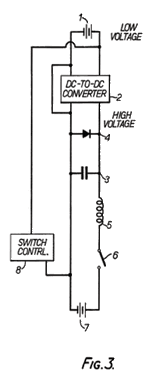
1. This circuit was in development in 1973 when John Bedini and Ron Cole called on E.V. Gray. It probably originated with Mr. Marvin Cole and really was not a bad concept if it had worked.
2. Its purpose (speculated) was to replace the Thyratron/ Ignitron switching system (that was energy hungry and used on the early Pulse Motors) and used to discharged the anomalous energy in the storage capacitors through the opposing electromagnets in the engine. The other switching method used on the EMA4 was direct rotating contacts, but these didn't provide precise enough switching times to maximize the HP output.
3. The circuit that generated the anomalous converted energy is not shown or disclosed in this circuit; except for the shunt diode and storage capacitor. I believe that the OU part of the circuit included the Floating Flux Field (FFF) but also several other required components (one being a spark gap) that were not disclosed in the patent.
4. The Lion's share of the stored energy does not go through the CEST but rather through the sealed spark gap #42 (probably a commercial sealed hydrogen device). Only 10% or less of the switching energy goes through the CEST. See the reference Patent by Phinney which is listed on the Pulse Engine patent to see how this all works out. For those who are interested I have a 30 page paper on the subject to explain my speculated development of the various circuits that have been observed. The polarity of the series diode was an artifact error from Mr. Ron Cole’s notes. (But who knows)
5. This CEST approach was only used on the EMA6 Free Energy Engine for about four months and then discarded. Mr. Hackenberger went back to the direct rotating contacts and got the system to work. There was something about a fixed arc that failed in this application. A stretched or dynamic arc seems to have worked much better. This was in 1976. The non-classical energy converters were hidden in those three each four terminal cans that were held out to be capacitors. Actually they were custom made passive circuits that processed the two opposing HV square waves from the power supplies. I'm sure that those cans also contained the storage device. It is rumored that it was a mica capacitor (to be verified)
6. By 1979 Richard was back to using Thyratrons/Ignitrons. By this time the team was no longer working on automotive engines but rather irrigation pumps in which the energy overhead of the switching elements was no longer as much of a consideration.
7. In 1980 Nelson Schlaft removed all of the Thyratrons in favor of a Zener Diode trigger approach for the Ignitrons. His retrofit (unknowingly) probably removed all of the circuit components that were generating the anomalous energy on the "Blue Engine". Or else the OU circuits (that looked like capacitor cans) were already removed. However, one of the dual two phase HV power supplied survived.
8. From 1981 until his death E.V. Gray was attempting to sell licensing rights to this technology, but was in sore need of approved patents that would satisfy his investors. A re-work of the failed CEST approach seems to have filled the bill and would certainly not disclose anything about the real technology yet look exotic enough to be genuine.
9. The only CEST type device built after 1976 was the single unit used just for bogus video advertisement production. In my opinion, attempting to figure out any of the details of the CEST circuit is not a good use of time or effort. The REAL non-classical circuit was never disclosed and perhaps never written down. It was too simple and to easy. No patent document could protect it for very long. It somehow takes the HV square wave pulses and converts them into "something" that can be stored in a capacitor device.
Never the less, the idea of finding some kind of non-classical response in a CEST type of device (like what lamare is proposing) is still a possibility. I just don't think that is what Hackenberger was doing with it.
The 80's British patent appears to me to be just a block diagram of the CEST circuit. I never paid much attention to it. However it does hint at the OU converter circuit as being "an inductive device". I'm sure that this circuit is indeed a general block diagram of the Free Energy Engines, but does not disclose enough detail to engineer the system. It does establish that the wet cell battery is a required component and not just a means to recapture the excitation energy. It also shows the importance of the shunt diode coupled with the storage capacitor.
For now we need to know how that "inductive device" (that includes the FFF) was constructed and why it needs those HV square waves.
Mark McKay
Originally posted by Aaron
View Post
Dear Aaron,
Here is my opinion on the operation/history of this circuit. Subject to change with additional data and/or experimental results.
1. This circuit was in development in 1973 when John Bedini and Ron Cole called on E.V. Gray. It probably originated with Mr. Marvin Cole and really was not a bad concept if it had worked.
2. Its purpose (speculated) was to replace the Thyratron/ Ignitron switching system (that was energy hungry and used on the early Pulse Motors) and used to discharged the anomalous energy in the storage capacitors through the opposing electromagnets in the engine. The other switching method used on the EMA4 was direct rotating contacts, but these didn't provide precise enough switching times to maximize the HP output.
3. The circuit that generated the anomalous converted energy is not shown or disclosed in this circuit; except for the shunt diode and storage capacitor. I believe that the OU part of the circuit included the Floating Flux Field (FFF) but also several other required components (one being a spark gap) that were not disclosed in the patent.
4. The Lion's share of the stored energy does not go through the CEST but rather through the sealed spark gap #42 (probably a commercial sealed hydrogen device). Only 10% or less of the switching energy goes through the CEST. See the reference Patent by Phinney which is listed on the Pulse Engine patent to see how this all works out. For those who are interested I have a 30 page paper on the subject to explain my speculated development of the various circuits that have been observed. The polarity of the series diode was an artifact error from Mr. Ron Cole’s notes. (But who knows)
5. This CEST approach was only used on the EMA6 Free Energy Engine for about four months and then discarded. Mr. Hackenberger went back to the direct rotating contacts and got the system to work. There was something about a fixed arc that failed in this application. A stretched or dynamic arc seems to have worked much better. This was in 1976. The non-classical energy converters were hidden in those three each four terminal cans that were held out to be capacitors. Actually they were custom made passive circuits that processed the two opposing HV square waves from the power supplies. I'm sure that those cans also contained the storage device. It is rumored that it was a mica capacitor (to be verified)
6. By 1979 Richard was back to using Thyratrons/Ignitrons. By this time the team was no longer working on automotive engines but rather irrigation pumps in which the energy overhead of the switching elements was no longer as much of a consideration.
7. In 1980 Nelson Schlaft removed all of the Thyratrons in favor of a Zener Diode trigger approach for the Ignitrons. His retrofit (unknowingly) probably removed all of the circuit components that were generating the anomalous energy on the "Blue Engine". Or else the OU circuits (that looked like capacitor cans) were already removed. However, one of the dual two phase HV power supplied survived.
8. From 1981 until his death E.V. Gray was attempting to sell licensing rights to this technology, but was in sore need of approved patents that would satisfy his investors. A re-work of the failed CEST approach seems to have filled the bill and would certainly not disclose anything about the real technology yet look exotic enough to be genuine.
9. The only CEST type device built after 1976 was the single unit used just for bogus video advertisement production. In my opinion, attempting to figure out any of the details of the CEST circuit is not a good use of time or effort. The REAL non-classical circuit was never disclosed and perhaps never written down. It was too simple and to easy. No patent document could protect it for very long. It somehow takes the HV square wave pulses and converts them into "something" that can be stored in a capacitor device.
Never the less, the idea of finding some kind of non-classical response in a CEST type of device (like what lamare is proposing) is still a possibility. I just don't think that is what Hackenberger was doing with it.
The 80's British patent appears to me to be just a block diagram of the CEST circuit. I never paid much attention to it. However it does hint at the OU converter circuit as being "an inductive device". I'm sure that this circuit is indeed a general block diagram of the Free Energy Engines, but does not disclose enough detail to engineer the system. It does establish that the wet cell battery is a required component and not just a means to recapture the excitation energy. It also shows the importance of the shunt diode coupled with the storage capacitor.
For now we need to know how that "inductive device" (that includes the FFF) was constructed and why it needs those HV square waves.
Mark McKay


Comment