Announcement

Collapse
No announcement yet.

Gray Tube Replication

Collapse
X
 
  • Filter
  • Time
  • Show
Clear All
new posts

  • Under the FFF

    Originally posted by nat1971a View Post
    I have read Tad Johnsons's description of his experiment many times. Wonder what ever happened to him.

    Anyway in my opinion the photos of the coil popping experiment, with a pvc pipe and FFF, are really a crude representation of the EMA motor. Of which the best performing motor was made of brass. Hence the reason why i have setup mine this way.

    In the attached photo you can quite clearly see a second layer on top of the pvc pipe. And why is there (black paint?) either side of the FFF. He must be trying to hide something.
    Dear Nat,

    Yea, we all have looked at the coatings under the FFF and noticed that there is something there that is not disclosed in its construction -at least in that demonstration equipment. It will probably be one of the many details that will never be solved completly.

    One speculative idea - PVC water pipe gets its color from added lamp black (carbon dust). This additive gretaly reduces the surface dielectric strength of this material. I understand that this is sometimes a problem in the construction of Tesla Coils. Anyway, perhaps Mr. Cole was not happy with the natural insulation properties and took measures to increase the integraty of the non-conductive surface, but who knows.

    If there was something under the FFF windings then its impact on the individual delay lines would not be balanced since the outer winding is further away than the inner winding. At lease if it was an electrostatic process. Now if it were a magnetic process then it would be a much more balanced system. Especially if that magnetic process was between the windings directly and not between the windings and the surface of the coil form.

    The EMA4 Engine definatly had the grounded engine case under the FFF windings, perhaps Mr. Cole thought that a ground plain would be needed here as well. Now, the Cannady demonstration claims that Mr. Gray used a coil of cable about 30" (6-8 turns)in diameter as his "Resses Coil". If this was the FFF then there was no ground plain involved.

    The EMA6 Engine doesn't display a component that can be taken as a FFF device, however there was plenty of room in those three switching power supplies to put them there. Maybe Mr. Hackenberger figured out a way to eliminate them from the technology? (I think not - he only hid it better).

    In any case, for what we see of the FFF cables it seems that they are built for HV - much higher than the nominal 3KV that the storage capacitors are alledgely to have attained. If 10-20KV pulses were being derived from the induction coils then the FFF would see a pretty hefty voltage drop from end to end as a sharp HV pulsed started its journy to the storage capacitor. The voltage at the capacitor would be much lower than the initial peak voltage of the pulse. Now, once the actual current wave was established the voltage would drop like a rock, but for the first few nano seconds the FFF would have to have the dielectric strenght to survive these impulses.

    I suspect that the FFF was the means to store the generated non-classical particles for a few millisceconds before they were used to fire the opposing electromagnts. Thus, all the insulation is intended to keep these particles contained. I further suspect that there were two polarities of these particles and they strongly attracted each other - that is why they stayed in the FFF reflecting from end to end until a low impedance path was provided. Perhaps, the ground plain help with the storage properties, but who knows?

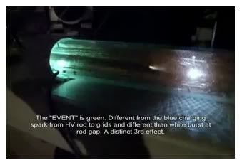
    I have never placed any kind of transducer in the center of my FFF coils, but it is certainly something to keep in mind. I'm still examining the details of short sparks that are generated with components lile this.

    Mark McKay

    Comment


    • Mark,

      It seems logical that they were trying to hide the FFF. The popping coil photos highlight the fact that the FFF was required for the magic to work. I just think that having a coil inside it is the missing part of the puzzle. Actually i have information in my possession that backs up this idea but it is based on Tesla technology.

      I hope you find some time to test having a coil inside the pvc pipe.

      I havent had a chance to continue testing much further. But i have noticed one thing. My transistors are being destroyed at an unprecedented rate. I think i am being forced to switch to relays which will mean my circuit will be 100% identical to the patent schematics.

      Cheers
      Nat

      Comment


      • Originally posted by Spokane1 View Post
        Dear penno64,

        A number of well qualified non-funded researchers have faithfully explored the technology that was suggested in Gray's 1986 patents and the novel proposals found in Peter Lindemann's Book "The Free Energy Secrets of Cold Electricity". It has been almost a decade and several dozen variations of this concept have been built but the hoped for "radiant energy" has not been found. (at least not disclosed)

        The interesting work that Aaron and his colleges on this thread are doing is a huge variation from the patent materials and should be considered a valid exploration subject in its own right.

        The detailed history of the CSET is far more grim and disappointing than most free-energy researchers want to face.

        The three so called CSET's that appeared on the EMA6 Free Energy Engine in Jan 9, 1976 were a far cry from the design presented in 1986, Even so these devices were removed from that Engine four months later because they apparently didn't work as planned. That Engine only produce 2 HP at first. It took at least a years to make it work right and that was without the CSET's.

        The only other CSET constructed by Gray after that was the one displayed in the 1986 promotion video. In an interview with Mark Gray (E.V. Gray's son working with him at the time) it can be easily determined that the effort was a fake and just a means to provide video footage for his sales campaign.

        There are a lot of other facts and circumstances that prove to me that the CSET started out (in 1973) as a means of HV switching in an attempt to eliminate the power hungry Thyratrons. But, it didn't work out, and then became a prop for bogus demonstrations.

        Don't get me wrong, The overall Gray Technology is vastly powerful and just short of pure magic. It appears (to me)that the non-classical process does indeed take place within an arc - just not the one contained within the CSET. The anomalous particles do not appear to exit the conductors at 90 degrees, but flow according to their own rules like classical electrons contained within the wires.

        This is my personal assessment from a long and detailed study of the available documentation and the testimony of a number of first hand players. If there is anyone who has a different view, based upon validated history, I would certainly like to discuss the issue with them in detail.

        If you want to mess around with HV light shows and interesting looking setups then the CSET and a Neon Sign transformer are the place to go. The equipment is cheap and you can pretend that you are going to solve the world's energy problems all day long. If you are really interested in a reverse engineered solution to the actual E.V.Gray technology then you are in for a very long and difficult road (plan on at least 10 years). There is just not that much left for us to go on. But, a few things have shaken out of the tree recently.

        Mark McKay, PE
        Dier Mark!
        I am one of those who have followed with interest your works. Some of them I have translated into Russian and posted on the website at the address given below.
        But this is not important. In my opinion, I was able to penetrate into the " great mystery " CSET Edwin Gray, as you and I would like to report. Despite the fact that I'm pretty sure I translate technical articles from English into Russian, ( including yours, and with comments ), my translation of his or others' works and from Russian into English is terrible. So I'm not even going to try to translate the articles into English - you are much simpler and more reliable to include in the Google Chrome browser interpretation, special. You know the terms... - I think you will understand.
        I suggest you look at my articles at

        ðÅÒÅ×ÏÄÞÉË Google

        If you are interested in my articles, you can transfer them to a good English (of course, with an indication of the author). Your article about the study Edwin Gree I translated into Russian as possible. Finished my translations of your work on Russian already posted at the above website.
        Sincerely yours,
        Leonid Volkov - (Zaporizhzhja, Ukraine).
        Last edited by lvleon; 07-27-2013, 03:10 AM.

        Comment


        • E.V. Gray Research in Russia

          Dear Ivleon,

          Thanks for passing on my articles and comments about the E.V.Gray technology to your research associates.

          If you would like more technical history, photos, drawings, and engineering speculations please email me at mmckay@simplexgrinnell.com

          I have several pages of additional documentation that you might like to consider for your research.

          I find the contributors on the blog that you referenced to be highly technical and very aware of other parallel classical studies. It is good to find such open minded individuals with an interest in this fringe subject.

          Mark McKay

          Comment


          • In regards to the Plasma Burst - Gray Event, it seems that without a
            coil connected to the output there is no 'Green Plasma'.

            Has the source of this colorful light been determined yet?
            Could it be the impedance of the coil is such that this already
            momentus event is caused to increase in magnitude and
            somehow oxidize stuff?

            Would using steel or silver-plated metal parts remove the hue?

            [ video ]

            Last edited by geotron; 10-30-2011, 11:37 AM.

            Comment


            • Originally posted by geotron View Post
              In regards to the Plasma Burst - Gray Event, it seems that without a
              coil connected to the output there is no 'Green Plasma'.

              Has the source of this colorful light been determined yet?
              Could it be the impedance of the coil is such that this already
              momentus event is caused to increase in magnitude and
              somehow oxidize stuff?

              Would using steel or silver-plated metal parts remove the hue?

              [ video ]

              All is as it should be! Open any book, directory on microwave technology, and look at the distribution of electric charges and magnetic field lines along the coaxial waveguide.
              Now compare the picture of the book that you see here. It seems???
              If connected to the collector inductance, the situation is compounded, which is also quite natural.
              It's for this reason Edwin Gray in his patent provided a special spark gaps - to prevent the ionization of the gas where it's absolutely not need!
              Any steels, any metals don't remove the ionization lights hue!
              Only two gap spark!
              Last edited by lvleon; 10-30-2011, 10:12 PM.

              Comment


              • mark,

                How are your experments going? Are you able to post some pictures?
                I have been busy converting my circuit to use relays as transistors are a waste of time

                Cheers
                Nat

                Comment


                • Gray Technology Exploration Experiments

                  Originally posted by nat1971a View Post
                  mark,

                  How are your experments going? Are you able to post some pictures?
                  I have been busy converting my circuit to use relays as transistors are a waste of time

                  Cheers
                  Nat
                  Near Nat,

                  Thanks for the interest. I have filled up memory allotment for photos on this site and I don't have the access resources to set up an account with a photo hosting service. But I shall describe what I'm doing.

                  Consider some basic reported facts about the nature of this technology that Gray's associates developed/discovered as described from the Cannady Interview and the Hackenberger Engineerign report.

                  1. 30 seconds was needed to charge up something (assumed to be the storage capacitors but may have been the common mode choke) before there was enough "Cold Electricity" to do the demonstration. Peter Lindemann claims that this delay time requirement was common to all of Gray's demonstrations including the original "Black Boxes"

                  2. During this entire charging process a small spark gap was operating.

                  3. Mr. Gray disclosed in this intervew report that all of "his" circuits required a spark gap.

                  4. Mr. Hackenberger, in his report, describes how the arc is the foundation of this technology and how it might interact with Oxygen to produce the excess energy and still be a calssical process.

                  The fact that the "Cold Electricity" has to be generated and stored over a period of many seconds implies that this is some kind of particle that can be stored and not a longitudinal wave or other similar EM phenomena.

                  Now, consider the power supply schematic disclosed in the Pulse engine patent. WHERE IS THE CONTINOUS ARC? Its not there. It has been purposily removed. OK, so where should it have been put? Really, there are not many places it could have gone. The most obvious (to me) is right between the two large storage capacitors. This requires that the 2nd power supply needs to have a polarity change. Now we have a circuit the resembles several other historical Free energy circuits.

                  They are: (with slight variations in each)

                  The Tesla Radio Transmitter (as describes on Wikipedia under Spark Radio)
                  The Sir Oliver Lodge Radio Transmitter
                  The Prentice Circuit
                  The Eric Dollard Radiant Energey Transmitter (The Video)
                  The Stan Myer power supply (the common mode choke portion)

                  This circuit involves two equal capacitors, two equal inductances and/or a delay line (or transmission line transformer), and a spark gap. The Gray and Myer circuits employ a diode.

                  How much do we know about the operation of this kind of circuit in pulse mode? Not much, most of the historical work was done with RF frequencies.

                  so, I'm learning about how this circuit functions under conditions that might have been found in the Gray Technology.

                  Some Tid-Bits I have observed:

                  1.The large series storage capacitors will allow an arc to take place.

                  2. Each spark will charge the capacitors to some degree until a voltage is reached where the spark will no longer strike. In this setup it is about 2-3 shots. This implies that at the frequencies that Gray's associates used (between 100 and 8KHz) each individual pulse was very low energy - far lower that what I'm working with. They were using the pulsed output of a transformer and I'm using an isolated charged capacitor - which is not really the same thing.

                  3. The series inductance will limit the peak current. With a 5 uf capacitor charged to 3000VDC discharging through a 0.014" gap and 46 mH of inductance the peak current is about 2.3 Amps

                  4. The lowest resistance of the arc is about 14 Ohms - this is the lower limit of the negative resistance process.

                  5. The current pulse duration is aobut 400 micro seconds. When using a diode as shown in the Gray Pulse engine patent a half wave sine wave results.

                  6. The size of the storage capacitor determines the pulse width. The initial charge on that capacitor determines the loop voltages and peak current.

                  7.The initial supply voltage from the capacitor is divided between the two large loop capacitors and results in a major reduction in the actual voltage avaliable to strike the arc. This suggests that a higher strike voltage was used.

                  8. In this setup a minimum voltage is required to get the gap to strike quickly. If the voiltage is to low the gap "Dithers" (the technical term is "Jitter") and will sit there for several micro seconds before the arc strikes. Different materials for the electrodes may improve this. Right now I'm using slotted round head brass #6 screws gapped at 0.014".

                  9. My FFF adds a whole bunch of "Hash" to the observed current trace as the current is increasing. Once the current pulse reach its peak all this "Hash" dissapears.

                  10. This current hash is a series of generally consistant wave packets composed of four frequencies that range from 20 MHz to 774 MHz (the range of my scope). The frequencies switch from one to the next in a regular fashion. This is certainly more complex than I expected. I have no idea where these come form (could be instrument artifact) or how they are generated. But when the FFF coil is removed they dissapear and all I get is the residual Hash from the initial striking arcs generated in my mechanical switching contactors at the start and end of the current pulse. I would like to eleminate this contact Hash, but I want to make sure it is not asscoiated with the phenomena that I'm looking for.

                  11. I'm using a Pearson 110 Wide Band Current Transformer - 50 MHz. This Hash manifests as quick and large magnitude spikes riding on the current base line. Now with 46 mH of inductance in the loop circuit the current can't change that fast with that magnitude. So, I'm not measuring current. I'm picking something else up that the probe and the scope are reporting as current spikes and they seem to come from the FFF and the mechanical contactor.

                  So, How and where does one look for non-classical particles when using equipment that may not even detect them, or worse yet may allow them to escape through the instrument ground? (Issues to keep me awake at night).

                  One proposed method is to eleminate the instrumentation (after all the basic tests are done) then attempt to store these unseen particles and then pop them through a small set of opposing coils to observed any increase in the degree of stored energy.

                  The question is "Where were these particles stored?" The dual storage capacitors like Gray would have you believe? Or the transmission line? Maybe both? Maybe neither.

                  I'm certainly going to be occupied this winter attempting to answer these questions.

                  I do know that Mr. Hackenberger designed an advance transistor switching power supply for the "Blue Engine" that still has two HV outputs. Why two outputs? Two power supplies were used in the Pulse Engine Patent as well - so it must be important.

                  I suspect that the FFF was a 1:4 Transmission Line Transformer to boose the strike voltage - but it may have done other things as well - if this Hash I'm observing is anything important.

                  Mark McKay

                  Comment


                  • @Mark: you may want to subscribe to Dropbox. Works very well and you get 2 GB of free storage space, which includes a nice photoalbum....

                    One of my albums: Dropbox - Photos - Simplify your life
                    Last edited by lamare; 11-03-2011, 05:09 PM.

                    Comment


                    • Photo Hosting

                      Originally posted by lamare View Post
                      @Mark: you may want to subscribe to Dropbox. Works very well and you get 2 GB of free storage space, which includes a nice photoalbum....

                      One of my albums: Dropbox - Photos - Simplify your life
                      Nice idea Lamare - but those sites are blocked on my company computer and I don't have Internet at home - to far out in the country.

                      I have drafted a schematic of this week’s experimental circuit. But my memory allotment is full. Does anyone know how I can deleat old photos from this forum?

                      Mark McKay

                      Comment


                      • http://www.energeticforum.com/forum-...ed-images.html

                        perhaps this helps

                        Comment


                        • Mark,

                          sounds like you have been busy with experimenting and research! i am still betting my money on the FFF interacting with the motor casing or some variation of it.

                          Hope you can post some photos of your setup. Out of curiosity are using transistors or relays?

                          Cheers
                          Nat

                          Comment


                          • Experimental Circuit of the Week

                            Originally posted by nat1971a View Post
                            Mark,

                            sounds like you have been busy with experimenting and research! i am still betting my money on the FFF interacting with the motor casing or some variation of it.

                            Hope you can post some photos of your setup. Out of curiosity are using transistors or relays?

                            Cheers
                            Nat
                            Dear Nat,

                            I finally got the method down on how to delete old photos. It reqired that I re-visit each past post and then use the photo manager to remove the material. Time consuming. I removed all my photos from the first 30 pages of this thread. I hope who was ever interested in that material got copies of it because its now all gone. At the most only 41 people viewed any of my attachments.

                            We sure could use a few minor breakthroughs to generate some more interest in this important field of exploration.

                            The attached drawing is the "Circuit of the Week". It is designed to examine individual pulses. The switches are motor contactors. The "Charge" contactor is rated at 550VAC @ 100 Amps. The "Fire" contactor is rated at 550VAC @ 30 Amps. I'm charging my storage capacitor up to 3500 VDC, so I have already exceeded the voltage rating of both contactors - but they seem to work. The problem with the contactors is that they introduce Hash into the observed wave forms. Perhaps that is anecessary evil for now.

                            Monday I shall have a fe photos for you to look at.

                            Mark McKay
                            Last edited by Spokane1; 02-10-2012, 05:29 PM. Reason: Attachment removed to make space

                            Comment


                            • wow!!! thats some professional setup you have there...can't wait to see the photos...well done

                              Comment


                              • Old Coax FFF Setup

                                Originally posted by nat1971a View Post
                                wow!!! thats some professional setup you have there...can't wait to see the photos...well done
                                Dear nat,

                                Here are some photos of an old (2008) attempt at generating "radiant energy" using a coax FFF (RG59) with a conductive coil form and a chopper power supply suggested by the Gray Pulse Engine patent.

                                I'm using a ignition coil for the step-up transformer with transistor choppers. The aim of this experiment was to charge the 40 uF capacitor bank to 3KV and see how high the popping green coils on the right would go (they jumped about 45"). Then charge the capacitor bank directly from the 5KV Fluke power supply in the back. Then compare the differance.

                                In this attempt there was no differance in the height obtained from the Gray power supply or the Classical Power Supply. Obvisouly I hadn't hit upon the "Trick" in this round.

                                Best of luck in working with FFF's with conductive coil forms. I certainly didn't do an exhaustive exploration of this approach.

                                Mark McKay
                                Last edited by Spokane1; 02-10-2012, 05:32 PM. Reason: Remove attachments to free up space

                                Comment

                                Working...
                                X