Announcement

Collapse
No announcement yet.

Gray Tube Replication

Collapse
X
 
  • Filter
  • Time
  • Show
Clear All
new posts

  • reversed diode

    Lamare,

    Doing it this way:


    is the only way to get the capacitor to discharge at a much faster rate. If you can get the capacitor to discharge like that with the diode in the conventional direction, I'd like to see it but all my experiments show me otherwise.

    Doing it the direction Bedini shows in his diagram - the capacitor discharge is accelerated as if it is actively pulled out of the capacitor and the resistance is gone that normally controls the discharge speed. (negative resistance)
    Sincerely,
    Aaron Murakami

    Books & Videos https://emediapress.com
    Conference http://energyscienceconference.com
    RPX & MWO http://vril.io

    Comment


    • Originally posted by Aaron View Post
      Lamare,

      Doing it this way:

      <snip image>

      is the only way to get the capacitor to discharge at a much faster rate. If you can get the capacitor to discharge like that with the diode in the conventional direction, I'd like to see it but all my experiments show me otherwise.

      Doing it the direction Bedini shows in his diagram - the capacitor discharge is accelerated as if it is actively pulled out of the capacitor and the resistance is gone that normally controls the discharge speed. (negative resistance)
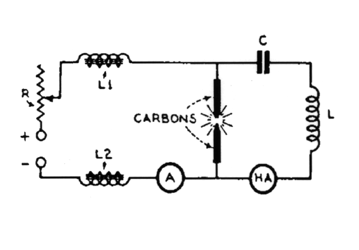
      What is essential is to get the spark gap into it's negative resistance area of operation, because that is needed to create a high frequency resonator using the self-induction of the rod as you would normally use a coil. In order to do that, you need a certain DC bias current trough your spark gap.

      Once you get the situation that the self-inductive rod is oscillating, then it radiates either Hertzian or longitudinal waves, which means you get transmission of energy into space in the shape of waves, energy that is drawn from the capacitor and therefore rapid discharge of your capacitor.

      In other words: with the correct bias, you get oscillation and therefore discharge of the capacitor energy into space. Without the correct bias, you don't get an oscillation and therefore no discharging of energy into space and thus no rapid discharge of your capacitor.

      In your case, the diode is operated in reverse mode, because you have high voltage at the spark gap, which discharges into the direction of the low voltage. And apparantly, the reverse characteristics of a diode are such that they can, under certain conditions, provide the proper bias for your spark gap.

      A triode is a device with other characteristics. So, you can't just see it as a diode in the other direction, especially not when you apply a steering voltage to its grid. By applying a voltage to the grid of the triode, you can control the amount of current that flows trough your spark gap and therefore can get it into it's negative resistance region of operation, which gets you the oscillation and therefore the discharge of energy into space in the shape of either an EM or a LD wave.


      So far, so good.

      So, we can get the rod into a high frequency oscillation, with a frequency in the order of 1 GHz, very similar to the Poulsen arc converter.

      The trick is to get this oscillation such that the discharge into space comes in the shape of a longitudinal dielectric wave and NOT an electromagnetic wave, which means you have to kill the HF magnetic component and therefore the HF current, meanwhile maintaining the DC bias current.

      And it appears that can be done using a balun, as I do with my antenna, which actually has quite a lot of similarities with the Gray tube.
      Last edited by lamare; 01-10-2012, 09:10 PM.

      Comment


      • diode position

        If anyone can get the capacitor to discharge at a very high speed with the diode in the conventional direction, that will be interesting.

        I just know that when the diode is reversed like what I point out, the capacitor discharges much faster than the "ambient" discharge speed 100% of the time.

        Normal discharge follows a fairly steady slope similar to a 45 degree angle going down.

        Doing it my method, 66% of the capacitor is discharged almost instantaneously and the last 33% of the capacitor then goes down at a 45 angle slope.

        The reverse diode method causes this to happen every single time. The impedance that the capacitor's discharge normally sees is almost completely removed with this method.

        My theory is simple - you are forcing both high voltage and low current over the gap simultaneously with low voltage and high current. This forces the high voltage positive to be associated with the high current and thus attracting it from the cap at a higher speed because of the higher pressure/vaccum associated with the higher voltage. The current from the low voltage source is being pulled on by a much higher voltage than its own low voltage positive and this is why the resistance disappears. And this works with or without an inductor in line - so with an inductor, the cap discharges into it without (at least greatly reduced) the impedance of the coil slowing down the rise time - so the coil actually gets charged almost instantaneously because of this negative resistance.

        By having the diode in the conventional forward direction, the low voltage high current source appears to be prohibited from mixing with the high voltage low current over the same gap.

        When you say oscillation, you're wanting to see an oscillation across the terminals of the capacitor discharging? A typical dampened oscillation waveform like this?

        Sincerely,
        Aaron Murakami

        Books & Videos https://emediapress.com
        Conference http://energyscienceconference.com
        RPX & MWO http://vril.io

        Comment


        • Originally posted by Aaron View Post
          If anyone can get the capacitor to discharge at a very high speed with the diode in the conventional direction, that will be interesting.

          I just know that when the diode is reversed like what I point out, the capacitor discharges much faster than the "ambient" discharge speed 100% of the time.

          Normal discharge follows a fairly steady slope similar to a 45 degree angle going down.

          Doing it my method, 66% of the capacitor is discharged almost instantaneously and the last 33% of the capacitor then goes down at a 45 angle slope.

          The reverse diode method causes this to happen every single time. The impedance that the capacitor's discharge normally sees is almost completely removed with this method.

          My theory is simple - you are forcing both high voltage and low current over the gap simultaneously with low voltage and high current. This forces the high voltage positive to be associated with the high current and thus attracting it from the cap at a higher speed because of the higher pressure/vaccum associated with the higher voltage. The current from the low voltage source is being pulled on by a much higher voltage than its own low voltage positive and this is why the resistance disappears. And this works with or without an inductor in line - so with an inductor, the cap discharges into it without (at least greatly reduced) the impedance of the coil slowing down the rise time - so the coil actually gets charged almost instantaneously because of this negative resistance.

          By having the diode in the conventional forward direction, the low voltage high current source appears to be prohibited from mixing with the high voltage low current over the same gap.

          When you say oscillation, you're wanting to see an oscillation across the terminals of the capacitor discharging? A typical dampened oscillation waveform like this?

          I'm not sure you understood that I agree that a semiconductor diode should be in reverse in order to provide a DC bias for the spark gap, which is the direction you have drawn it.

          This is the schematic of Duddel's singing arc, on which the Poulsen arc converter is based:

          Any piece of wire has a certain self inductance and a certain self capacitance, and can be put into resonance as a tank circuit, which normally consists of an LC circuit, either in series or in parallel.

          If you want to get such a tank circuit into continuous oscillations, you have to make up for the energy that is lost c.q. radiated into space. One of the ways to do that is to use a power supply and put a component with a negative resistance characteristic in the resonant loop.

          In this sense, negative resistance means that the device has an area of operation wherein an increase in voltage over the device, results in a decrease of the current trough the device.

          See this article: LAMBDA DIODE


          To make a negative resistance oscillator we simply connect a tuned circuit in series with the Lambda circuit and the drain to source supply and set the supply voltage to a suitable level for oscillation to occur.


          The advantage of this type of oscillator is that two-terminal (i.e. no taps) inductance coils are all thats needed!
          And of course a coil has a self-capacitance, so you can also do without the capacitor. And a piece of wire also has a self-induction as well as a self-capacitance, so the main rod in the CSET can act as a tank circuit, albeit that the operation frequency will be very high.

          As you can see, the negative resistance region of such a practical negative resistance device is not in the area around 0V, but it needs a bias, an offset, which is why there is an adjustable resistor in the circuit with the tunnel diode.

          A spark gap also has such a negative resistance region of operation, but it needs current-based biasing, not a voltage based biasing, which can be provided by a semiconductor diode in reverse mode. So, that is why I agree that a semiconductor diode has to be in the direction you have drawn it and that my earlier conclusion that you need a triode is incorrect.

          However, a triode does not conduct at all in reverse direction and it has a grid to control the current trough it in its forward direction. So, I think the triode, as an active component, is also drawn in the correct direction.

          Different component, same result: a DC bias to put the spark gap in its negative resistance region of operation flowing from the HV cap trough the rod towards ground, trough a series of other components.

          The oscillation I am talking about is a standing wave propagating back and forth along the rod itself, along the principles of the Tesla coil as described by Dollard:

          http://www.tuks.nl/pdf/Eric_Dollard_...Coils(OCR).pdf

          The formation of the energy impulse involves the discharge of a capacitor with the highest practical stored energy into an impedance (inductive) of the lowest practical value, and the discharge path is coupled to an energy supply through a negative resistance device. This negative resistance is classically a spark discharge, but a superior plasma device needs to be developed to enhance efficiency. Under optimal conditions the exponent of oscillation amplitude will be positive over a sustained period of time.
          The net result of this system is the production of an extreme impulse of M.M.F.
          He essentially describes the production of extreme impulses of magnetic energy by the discharge of a cap into an inductor with a low value, Like a straight wire of a few centimeters, such as the rod in a CSET...

          Hereby you get a standing impulse wave with growing amplitude, because of the energy supply trough the negative resistance device, the spark gap, and the resonance characteristics of the practical inductance, which also has a certain (distributed) self-capacitance.

          So, in the case of the CSET, your energy supply is the high voltage capacitor...


          And about the idea of electron based currents in these kinds of systems, let me just quote Eric Dollard:

          Originally posted by T-rex View Post
          When considering waves on coiled windings, leave out the electrons, let us forget them once and for all. They are for electronic devices (RG) NOT for electrical devices (LC). Forget the electrons, forget it!
          Of course, this also applies to waves on straigt-wire inductors...
          Last edited by lamare; 01-10-2012, 11:44 PM.

          Comment


          • Arc Oscillator details

            Dear lamare,

            In your review of the Polson and Duddel arc oscillators keep in mind that both systems require the introduction of external substances to promote the negative resistance process. Duddel used various kinds of ionic salts while Polson used organic carbon compounds.

            There was another Spark Radio system used in Germany by the Telefunken company that employed zinc electrodes. It appears that zinc provides the necessary environment for negative resistance - however its maximum current range was limited so that when Marconi copied everyones work he snatched the Polson design for his across the Atlantic station.

            I understand that to get a Polson arc to work right requires some serious constant current. I don't know what the Duddel arc system requires for stable operation. I know that the zinc-zinc approach will function with as little as 300 mA.

            Do you suppose that the silver-silver electrodes might have been a means to have a low current negative resistance oscillatior? I certainly haven't tested the arrangement yet to see if silver works like zinc (or maybe better).

            All of these systems have serious issues with bandwidth vs. power output.

            Mark McKay

            Comment


            • cap discharge speed reduced - different from neg resistance component effects

              Originally posted by lamare View Post
              I'm not sure you understood that I agree that a semiconductor diode should be in reverse in order to provide a DC bias for the spark gap, which is the direction you have drawn it.

              One of the ways to do that is to use a power supply and put a component with a negative resistance characteristic in the resonant loop.

              In this sense, negative resistance means that the device has an area of operation wherein an increase in voltage over the device, results in a decrease of the current trough the device.
              Lamare, I get what you're saying, was just referring to you saying both directions are correct but with the triode in the conventional direction, yes needs a trigger but to date, nobody has achieved the fast discharge and have destroyed triodes at $100 a pop doing it this way - if that is what you're referring to. Nobody has ever demonstrated anything unusual using a triode in the conventional manner to allow the HV to go through to the battery. The discharge is normal and nobody has shown any difference in the discharge speed of the capacitor.

              The removal of resistance from the capacitor when using the reverse diodes doesn't seem to caused by any certain component like a transistor that has a negative region like a 2n2222 or mjl21194, etc... I have found these regions in some mosfets too. But in any case, the removal of resistance is from a blending of hv/low current with lv/high current. This is a completely different kind of discharge than a conventional discharge of the cap over the gap (which isn't even a true disruptive discharge) - and is completely different from a disruptive discharge like a peaking cap. The mixing of hv and lv with their associated currents is what removes the resistance - it is a pressure/suction effect - in my opinion of course and is independent of the devices or components.

              Basically, seems very different from this: "the device has an area of operation wherein an increase in voltage over the device, results in a decrease of the current trough the device. " I understand this in terms of different transistors, etc... but the mixing effect with the cap is different. The cap discharge time is decreased substantially.

              Using this method and discharging the cap into an inductor, it is as if there is no lenz law happening - no back emf to oppose the forward charge. That appears to be completely different from the typical negative resistance of a gap, transistor going negative, etc...
              Sincerely,
              Aaron Murakami

              Books & Videos https://emediapress.com
              Conference http://energyscienceconference.com
              RPX & MWO http://vril.io

              Comment


              • Originally posted by Aaron View Post
                The removal of resistance from the capacitor when using the reverse diodes doesn't seem to caused by any certain component like a transistor that has a negative region like a 2n2222 or mjl21194, etc... I have found these regions in some mosfets too. But in any case, the removal of resistance is from a blending of hv/low current with lv/high current. This is a completely different kind of discharge than a conventional discharge of the cap over the gap (which isn't even a true disruptive discharge) - and is completely different from a disruptive discharge like a peaking cap. The mixing of hv and lv with their associated currents is what removes the resistance - it is a pressure/suction effect - in my opinion of course and is independent of the devices or components.
                If your theory is correct, then I think the attached schematic should also work. With this, you get a very steep pulse to your load coil when the spark gap breaks (make sure the ignition coil produces a positive HV spike; polarity of primary may be drawn wrong, I always confuse these), whereby the electric field, which propagates with either c or pi/2 times c, might energize the load coil, provided you have a steep rise time and a slow fall time of the pulse.

                Then, the diode with booster cap ensures that the discharge is uni-directional.


                The problem I have with this theory is:

                a) It does not explain why you would need grids in the CSET nor how the energy would be transferred trough the grids to the coil, unless you get an arc/spark discharge towards the grids too.

                b) It is very similar to Bedini's systems, which do produce COP>1, but are far less powerfull than what Gray was apparantly capable of.
                Attached Files

                Comment


                • Gray circuit and plasma discharge

                  Originally posted by lamare View Post
                  If your theory is correct, then I think the attached schematic should also work. With this, you get a very steep pulse to your load coil when the spark gap breaks (make sure the ignition coil produces a positive HV spike; polarity of primary may be drawn wrong, I always confuse these), whereby the electric field, which propagates with either c or pi/2 times c, might energize the load coil, provided you have a steep rise time and a slow fall time of the pulse.

                  Then, the diode with booster cap ensures that the discharge is uni-directional.


                  The problem I have with this theory is:

                  a) It does not explain why you would need grids in the CSET nor how the energy would be transferred trough the grids to the coil, unless you get an arc/spark discharge towards the grids too.

                  b) It is very similar to Bedini's systems, which do produce COP>1, but are far less powerfull than what Gray was apparantly capable of.
                  I think your drawing will work. I have placed the reverse diode on the other side of the gap before for different tests. But why not just put the coil in place of the diode?

                  I do want to clarify my previous statement about the plasma not being a true disruptive discharge. It is a real disruptive discharge - even more so than a peaking cap type discharge (it is quite a big faster) or other conventional disruptive discharge. The cdi discharge into the ignition coil of course is not disruptive - but the plasma effect that follows is disruptive. Not a comment in response to your reply - just a clarification.

                  The booster cap would need to be disconnected from the primary or it is just shorted out through the windings. I always placed the booster in parallel with the gap so that there isn't too much being discharged into the primary. The positive of the primary is usually in the middle instead of the bottom but doesn't matter in concept.

                  a) You don't need grids, I think that is all bogus to throw people off. What is important to understand is that the gap you see is the same as the gap between the rods and the grids in the Gray tube setup. That gap is NOT analogous of the gap between the rods. The gap between the rods is substituted with the HV diode between the primary cap and HV. 1 - hv discharges backwards into HV diode before jumping gap - that is analogous to the HV jumping over the gap between the rods into the LV side - lv side being the capacitor. THEN, when the diode shuts off, the HV turns away and has nowhere to go but over the gap (same as going from LV rod over to grid then through coil).

                  Here is an example of the comparison between my method and the Gray circuit. The LV source I show is the booster cap - however, the CDI cap on the front is also a LV source and works without the booster cap. Recovery cap and recovery battery are just there for examples - anyway, it is a perfect analogy to the Gray circuit (with the reverse diode as Bedini shows):


                  Another explanation showing what is happening in Gray tube according to the popular Gray patent diagram:

                  Sincerely,
                  Aaron Murakami

                  Books & Videos https://emediapress.com
                  Conference http://energyscienceconference.com
                  RPX & MWO http://vril.io

                  Comment


                  • When the energy of the tube is sent through the motor coil, sparking through it
                    to ground, the lower voltage capacitive resevoir ought to receive an uptake of
                    energy while it is happening to help replenish what is used. It would go through
                    the coil energizing another coil connected directly onto the source.

                    Comment


                    • Originally posted by Aaron View Post
                      a) You don't need grids, I think that is all bogus to throw people off. What is important to understand is that the gap you see is the same as the gap between the rods and the grids in the Gray tube setup. That gap is NOT analogous of the gap between the rods. The gap between the rods is substituted with the HV diode between the primary cap and HV. 1 - hv discharges backwards into HV diode before jumping gap - that is analogous to the HV jumping over the gap between the rods into the LV side - lv side being the capacitor. THEN, when the diode shuts off, the HV turns away and has nowhere to go but over the gap (same as going from LV rod over to grid then through coil).

                      Let's take a look at the fundamental physics behind these phenomena. Eric Dollard often referred to the work of C.P. Steinmetz, and the work particularly interesting in this regard is his "Elementary lectures on electric discharges, waves and impulses, and other transients (1911)", which can be found here:
                      Elementary lectures on electric discharges, waves and impulses, and other transients : Steinmetz, Charles Proteus, 1865-1923 : Free Download & Streaming : Internet Archive

                      The phenomena we are talking about here is what Steinmetz refers to as "transients" and which are fundamentally connected to the storage of energy in the space surrounding the conductors:

                      NATURE AND ORIGIN OF TRANSIENTS.

                      Electrical engineering deals with electric energy and its flow, that is, electric power. Two classes of phenomena are met: permanent and transient, phenomena.

                      To illustrate: Let G in Fig. 1 be a direct-current generator, which over a circuit A connects to a load L, as a number of lamps, etc. In the generator G, the line A, and the load L, a current i flows, and voltages e exist, which are constant, or permanent, as long as the conditions of the circuit remain the same. If we connect in some more lights, or disconnect some of the load, we get a different current i', and possibly different voltages e'; but again i' and e' are permanent, that is, remain the same as long as the circuit remains unchanged.

                      Let, however, in Fig. 2, a direct-current generator G be connected to an electrostatic condenser C. Before the switch S is closed, and therefore also in the moment of closing the switch, no current flows in the line A. Immediately after the switch S is closed, current begins to flow over line A into the condenser C, charging this condenser up to the voltage given by the generator. When the condenser C is charged, the current in the line A and the condenser C is zero again. That is, the permanent condition before closing the switch S, and also some time after the closing of the switch, is zero current in the line. Immediately after the closing of the switch, however, current flows for a more or less short time. With the condition of the circuit unchanged: the same generator voltage, the switch S closed on the same circuit, the current nevertheless changes, increasing from zero, at the moment of closing the switch S, to a maximum, and then decreasing again to zero, while the condenser charges from zero voltage to the generator voltage. We then here meet a transient phenomenon, in the charge of the condenser from a source of continuous voltage.

                      Commonly, transient and permanent phenomena are superimposed upon each other. For instance, if in the circuit Fig. 1 we close the switch S connecting a fan motor F, at the moment of closing the switch S the current in the fan-motor circuit is zero. It rapidly rises to a maximum, the motor starts, its speed increases while the current decreases, until finally speed and current become constant; that is, the permanent condition is reached.

                      The transient, therefore, appears as intermediate between two permanent conditions: in the above instance, the fan motor disconnected, and the fan motor running at full speed. The question then arises, why the effect of a change in the conditions of an electric circuit does not appear instantaneously, but only after a transition period, requiring a finite, though frequently very short, time.

                      2. Consider the simplest case: an electric power transmission (Fig. 3). In the generator G electric power is produced from mechanical power, and supplied to the line A . In the line A some of this power is dissipated, the rest transmitted into the load L, where the power is used. The consideration of the electric power in generator, line, and load does not represent the entire phenomenon. While electric power flows over the line A , there is a magnetic field surrounding the line conductors, and an electrostatic field issuing from the line conductors. The magnetic field and the electrostatic or "dielectric " field represent stored energy. Thus, during the permanent conditions of the flow of power through the circuit Fig. 3, there is electric energy stored in the space surrounding the line conductors. There is energy stored also in the generator and in the load ; for instance, the mechanical momentum of the revolving fan in Fig. 1, and the heat energy of the incandescent lamp filaments. The permanent condition of the circuit Fig. 3 thus represents not only flow of power, but also storage of energy. When the switch S is open, and no power flows, no energy is stored in the system. If we now close the switch, before the permanent condition corresponding to the closed switch can occur, the stored energy has to be supplied from the source of power; that is, for a short time power, in supplying the stored energy, flows not only through the circuit, but also from the circuit into the space surrounding the conductors, etc. This flow of power, which supplies the energy stored in the permanent condition of the circuit, must cease as soon as the stored energy has been supplied, and thus is a transient.

                      Inversely, if we disconnect some of the load L in Fig. 3, and thereby reduce the flow of power, a smaller amount of stored energy would correspond to that lesser flow, and before the conditions of the circuit can become stationary, or permanent (corresponding to the lessened flow of power), some of the stored energy has to be returned to the circuit, or dissipated, by a transient.

                      Thus the transient is the result of the change of the amount of stored energy, required by the change of circuit conditions, and is the phenomenon by which the circuit readjusts itself to the change of stored energy. It may thus be said that the permanent phenomena are the phenomena of electric power, the transients the phenomena of electric energy.

                      [...]

                      As seen, the capacity current is the exact analogy, with regard to the dielectric field, of the inductance voltage with regard to the magnetic field; the representations in the electric circuit, of the energy storage in the field.

                      The dielectric field of the circuit thus is treated and represented in the same manner, and with the same simplicity and perspicuity, as the magnetic field, by using the same conception of lines of force.

                      Unfortunately, to a large extent in dealing with the dielectric fields the prehistoric conception of the electrostatic charge on the conductor still exists, and by its use destroys the analogy between the two components of the electric field, the magnetic and the dielectric, and makes the consideration of dielectric fields unnecessarily complicated.

                      There obviously is no more sense in thinking of the capacity current as current which charges the conductor with a quantity of electricity, than there is of speaking of the inductance voltage as charging the conductor with a quantity of magnetism. But while the latter conception, together with the notion of a quantity of magnetism, etc., has vanished since Faraday's representation of the magnetic field by the lines of magnetic force, the terminology of electrostatics of many textbooks still speaks of electric charges on the conductor, and the energy stored by them, without considering that the dielectric energy is not on the surface of the conductor, but in the space outside of the conductor, just as the magnetic energy.
                      This last statement is very important. It totally turns our understanding of electricity upside down. Think about it. Dielectric or electrostatic energy is NOT stored on the surface of a conductor, but in the space OUTSIDE of a conductor. If this is true, how on earth could electrostatic energy be conveyed by "charge" (electrons) flowing INSIDE of a conductor?

                      WTH is going on here?

                      What more is totally misunderstood?

                      Tesla had some interesting things to say:

                      Tuks DrippingPedia : Tesla Prepared Statement80st Birthday
                      I returned to this country in 1892 eager to devote myself to the subject of predilection on my thoughts: the study of the universe.

                      During the succeeding two years of intense concentration I was fortunate enough to make two far-reaching discoveries. The first was a dynamic theory of gravity, which I have worked out in all details and hope to give to the world very soon. It explains the causes of this force and the motions of heavenly bodies under its influence so satisfactorily that it will put an end to idle speculations and false conceptions, as that of curved space. According to the relativists, space has a tendency to curvature owing to an inherent property or presence of celestial bodies. Granting a semblance of reality to this fantastic idea, it is still self-contradictory. Every action is accompanied by an equivalent reaction and the effects of the latter are directly opposite to those of the former. Supposing that the bodies act upon the surrounding space causing curvature of the same, it appears to my simple mind that the curved spaces must react on the bodies and, producing the opposite effects, straighten out the curves. Since action and reaction are coexistent, it follows that the supposed curvature of space is entirely impossible. But even if it existed it would not explain the motions of the bodies as observed. Only the existence of a field of force can account for them and its assumption dispenses with space curvature. All literature on this subject is futile and destined to oblivion. So are also all attempts to explain the workings of the universe without recognizing the existence of the ether and the indispensable function it plays in the phenomena.

                      My second discovery was a physical truth of the greatest importance. As I have searched the scientific records in more than half dozen languages for a long time without finding the least anticipation, I consider myself the original discoverer of this truth, which can be expressed by the statement: There is no energy in matter other than that received from the environment.
                      All right. So gravity can be explained with aether theory and it's energy is obtained from the invironment: the aether a.k.a. "space outside the conductor"...

                      Break - more to follow.

                      Comment


                      • plasma discharge

                        Lamare,

                        I'll have to look at the diagrams in the book to be more clear on what Steinmetz is saying - but it sounds like the energy outside the conductor is not just the ambient aether but polarized/organized aether outside the conductor aka "Heaviside Flow". Is that not the same thing?

                        It has been my understanding for quite a while that the energy flow over the wire is the "Heaviside Flow" and that we are only tapping 10 -13th (1/11 trillionths) of what we are polarizing/organizing by the source dipole.

                        Whether Dollard agrees with Bearden or not, on this matter, Bearden is essentially pointing out the exact same thing. Bearden isn't saying he discovered this - he is simply pointing out the references.

                        I'll have to look more at what Steinmetz is saying but I don't see at the moment that he is simply talking about the aether that just happens to be in the space around the conductor. I think the aether in the space around the conductor has been polarized by the potential difference between the + and - of the source dipole/capacitor/power supply, etc... then the aether is polarized and flowing over the space surrounding the conductor and is definitely not some "charge" just sitting on the wire. The charge claimed conventionally to be on the surface of the conductor I believe may be referred to as the "Poynting" component - just the part in contact with the conductor that ignores the entire massive flow of polarized aether around the conductor.

                        I agree 100% with that Tesla quote. I deduced that quite a while back. The reaction of aether to mass such as the earth is what I refer to as the "rebounding" of the aether - you push your finger into a balloon and that balloon pushes back on your finger. The effect of gravity is the reaction of the aether to the mass that displaces it. The curvature of space described by Einstein is simply a joke.

                        But in regards to this plasma - if it is the same kind of transient effect described by Steinmetz, I'm not sure. Do you know of a capacitor discharge by Tesla that had this same plasma effect? I know he described some like a gun shot, etc... but I'd like to see the circuit that did it.
                        Sincerely,
                        Aaron Murakami

                        Books & Videos https://emediapress.com
                        Conference http://energyscienceconference.com
                        RPX & MWO http://vril.io

                        Comment


                        • Remember one of Eric's first posts on this forum?

                          Originally posted by Dollard, E. P. (N6KPH) View Post
                          There are some very serious misconceptions in the world of Electrical Engineering today. (The writings of Oliver Heaviside and Proteus Steinmetz gravely warned about this...) Let us start with the YouTube MIT Physics Demo video that Armagdn03 posted a link to on 11-10-2009 on page 2 of this thread. This is a good demonstration for several reasons.

                          (This video: MIT Physics Demo -- Dissectible Capacitor - YouTube)

                          1.) Glass is a dielectric which can store electrical energy within its physical form. This should be common knowledge and not a surprise to anyone today…

                          2.) That this simple fact and reality “blows some people’s minds” clearly illustrates that it’s just all gone way, way, too far… The Einsteinian Lie has succeeded in instilling a mind virus in most everyone and also in confusing Main Stream “Scientists”, who today waste billions of dollars of funding each year, only to chase their own tails in a canonic sequence.

                          <snip>

                          I had a young student from Korea visit me a few years back. He had no problem understanding the basic concept of producing an energy synthesizing apparatus, because his mind was uncontaminated by all of the Bedini/Bearden falsehoods. The term Scalar Wave is an oxymoron, as scalar is part of the propagation constant that is NOT A WAVE! (Idiots!)

                          Most are clueless about the importance of the Variation of Inductance and Capacitance with respect to time – and synchronous parameter variations. Read chapter 21 (XXI) titled REACTION MACHINES in Charles Proteus Steinmetz’s book titled “Alternating Current Phenomena”. There is also a Russian paper (brought to me by the Korean student as a gift) titled: “UBER DIE ERREGUNG VON ELETRISCHEN SCHWINGUNGEN DURCH PARAMETERAENDERUNG” von L. Mandelstam und N. Papalexi, published in 1934 in: J. ZEITSCHRIFT FUR (umlaut on the U - as should also be on the first U in the title of the paper) TECHNISCHE PHYSIK Band IV, Heft 1, that continues with what Steinmetz teaches in his books, and takes it all the way (Title translation: Concerning the Excitation of Electrical Waves Through Parameter Changes). In one picture in the paper, there appears to be a brightly glowing incandescent lamp connected to a network, with no apparent connection to a power source. It appears to be an Alexanderson type Mag. Amp. operating in a self oscillation mode. (Alexanderson Patent # 1,328,797 Jan. 20, 1920): Even though my copy of the paper is in Russian, the equations speak for themselves and echo the work of Steinmetz and Alexanderson. Ernst Alexanderson emigrated to America because of Steinmetz’s book, - he was determined to work with Steinmetz after studying it. Steinmetz was forced to reverse many of his equations in later books and was severely criticized by physicist Michael Pupin of Columbia University for not using Maxwell’s ideas and instead developing a methodology that was actually useful and practical for engineers. (Read, “Steinmetz, Engineer and Socialist” written by Ronald R. Kline.) Here it was said that General Electric gave Steinmetz permission to create Electricity form the square root of minus one…
                          BTW, the Russian paper Eric referred to has recently been translated to English:
                          http://www.tuks.nl/pdf/Reference_Mat...ion%201934.pdf


                          All right.

                          So, dielectric (or electro-static) energy in/around a conductor is actually stored in the space outside the conductor, the aether, a medium with fluid-like properties. And we can see that this is true from the MIT dissectible capacitor demo. Does this mean that electrons are not for real and total utter rubbish?

                          No, I don't think so.

                          I think the idea of the existence of flowing electrons trough a wire or component is real and gives good results, provided you are using low frequencies, which also means: no sudden changes. No sharp edges, such as the discharge of a cap trough a spark gap. If electron flows were total rubbish, you could not explain semi-conductors and would also have a hard time explaining chemical reactions, such as occur in batteries.

                          So, if we want to get a better understanding of what electricity is, we have to change the idea that electricity is a flow of electrons trough a hollow tube with stiff walls. That one only goes so far and cannot explain the radiation of waves, etc. If we want to understand these, all we have to do is thinking about our tubes as being elastic. So, a conductor would be much more like a very elastic garden hose filled with motor oil, submerged under water. When one gently puts pressure on one side of the hose, the oil will start moving, but the hose also expands a bit. After a while, you get a steady state of oil flowing trough the hose and nothing happens in the water.

                          However, if you were to suddenly push a huge amount of oil into the hose under high pressure, the hose has no other choice but to swell up like a balloon at the side you apply the pressure, which also gives you a pressure wave in the water your hose is submerged in. The interesting thing is that the water moves much faster than the motor oil inside your hose, so the wave propagating trough the water will create pressure variations along your hose, which are not caused by the movement of the oil, but by the movement of the water.

                          So, now we have a much more accurate analogy of thinking about conductors and currents flowing trough them as well as waves propagating trough the water, the aether, around your conductor. Now let's take a look at what Eric had to say a couple of weeks ago:

                          Originally posted by T-rex View Post
                          The T.E.M. wave is always along the axis of the metallic geometry, tangent to the metallic boundary. Such is given by the “Co-axial Cable”. Conversely, the L.M.D. wave is always perpendicular to the axis of the metallic geometry, normal to the metallic boundary. Such is given by the “Transformer Winding”. The resulting complex propagation of v and u is a spiral with a tilt angle from the metallic axes of the coiled winding. Where T.E.M. waves drag into the metallic (electron flow) the L.M.D. wave bypasses the metallic (no electron flow) hence no Ohmic resistance. The factor pi over two is the composite propagation for only a unique set of parameters. See “The Oscillating Coil” part of the “Theory of Wireless Power” E.P. Dollard. Note here that errors found a way into the tables, but the equations are right. Now why could not the Corum’s figure this out? Why is it they make no reference to any work on this by Blume, Bewely, Dollard, and etc? The Corums, Well?
                          He clearly talks about waves interacting with electron flows, whereby one kind of waves DOES interact with an electron flow in the metallic, the conductor, and another kind of wave does NOT interact with the electron flow.

                          All right. So when we apply a sudden change of pressure to one terminal of a conductor, we are making big errors when we consider our conductor as being a stiff tube. What happens is that this sudden explosive pressure applied to our conductor cannot get the electrons flowing inside the conductor instantly, so the pressure has to go somewhere, at least temporary. So, shockwaves are being transmitted into the space surrounding the conductor, the aether. And these waves propagate much, much faster than the electrons inside the wire, while at the same time these shockwaves "drag into the metallic", which is why you get something extra with a "disruptive" or sudden discharge of a cap into a coil trough a spark gap.

                          And it is this shockwave that is responsible for the effect Aaron described:
                          Originally posted by Aaron View Post
                          Doing it the direction Bedini shows in his diagram - the capacitor discharge is accelerated as if it is actively pulled out of the capacitor and the resistance is gone that normally controls the discharge speed. (negative resistance)
                          So, I think the effect Aaron describes is real, but there are more tricks that can be pulled with these waves trough the aether. And Steinmetz also gave some hints in that direction in his already referred book on transients, etc.:

                          Standing waves and traveling waves, in which the coefficient in the exponent of the time exponential is positive, that is, the wave increases with the time, may, however, occur in electric circuits in which the wave is supplied with energy from some outside source, as by a generating system flexibly connected (electrically) through an arc. Such waves then are "cumulative oscillations." They may either increase in intensity indefinitely, that is, up to destruction of the circuit insulation, or limit themselves by the power dissipation increasing with the increasing intensity of the oscillation, until it becomes equal to the power supply. Such oscillations, which frequently are most destructive ones, are met in electric systems as "arcing grounds," "grounded phase," etc. They are frequently called "undamped oscillations," and as such find a use in wireless telegraphy and telephony. Thus far, the only source of cumulative oscillation seems to be an energy supply over an arc, especially an unstable arc. In the self-limiting cumulative oscillation, the so-called damped oscillation, the transient becomes a permanent phenomenon. Our theoretical knowledge of the cumulative oscillations thus far is rather limited, however.
                          Last edited by lamare; 01-13-2012, 10:58 PM.

                          Comment


                          • Originally posted by Aaron View Post
                            But in regards to this plasma - if it is the same kind of transient effect described by Steinmetz, I'm not sure. Do you know of a capacitor discharge by Tesla that had this same plasma effect? I know he described some like a gun shot, etc... but I'd like to see the circuit that did it.
                            I think it is the shockwave outside the wire that gives you this "sucking" force, which also expands to the LV booster cap and thus sort of gives the electrons at the LV part of the circuit a "push" in the right direction. Something "extra".

                            Something extra, which apparantly can be used to pull some energy out of the aether which you can use in your system. Basically the same "spike" Bedini likes to use.

                            However, now we understand that this has to do with "transients" and "interactions" with the aether, we can start thinking about possibilities of getting this principle into high gear.

                            And that means we have to design our interactions with the aether, we have to optimize our interactions with the aether. And that means HF radio engineering. Engineering of the transient..

                            And Eric told us exactly how to choose where in the system we want to get the aether to get our electrons moving, and where in the system we want the aether to stay away from our electrons:

                            Where T.E.M. waves drag into the metallic (electron flow) the L.M.D. wave bypasses the metallic (no electron flow) hence no Ohmic resistance.


                            (i.e.: L.M.D. should be L.D., but that's just a detail)

                            So, the trick seems to be to generate LM "no ohmic resistance" waves to get the aether going and to propagate that motion to where we want to use it (our coil), but to do it continuously instead of "disruptive".

                            And then we need to convert our LD wave into a TEM wave around our coil in order to let it "drag into" the metallic, our coil.

                            And that most of all means: matching of LD to TEM resonance frequencies in various parts of the system...

                            Comment


                            • There is a certain video in which a pulse motor is shown running with
                              the E.Gray technology, without the use of a flyback-type coil. It
                              appears they have mastered the technique. [ pulse motor experiment ]

                              Comment


                              • connection of FFF to commutator ring

                                Originally posted by Spokane1 View Post
                                The attached drawing shows the location of the FFF cables (the 18 each little circles on the outside of the Engine case in the middle) in relation to the end-to-end spacing of the "Major" electromagnets.

                                Mark McKay
                                Mr. McKay, do you have connection diagram of FFF to commutator ring to motor electromagnets ? The commutator is made of alumunium slip ring and copper contacts, what material is the brush made of ? Thanks.

                                Wicaksono

                                Comment

                                Working...
                                X