Announcement

Collapse
No announcement yet.

Gray Tube Replication

Collapse
X
 
  • Filter
  • Time
  • Show
Clear All
new posts

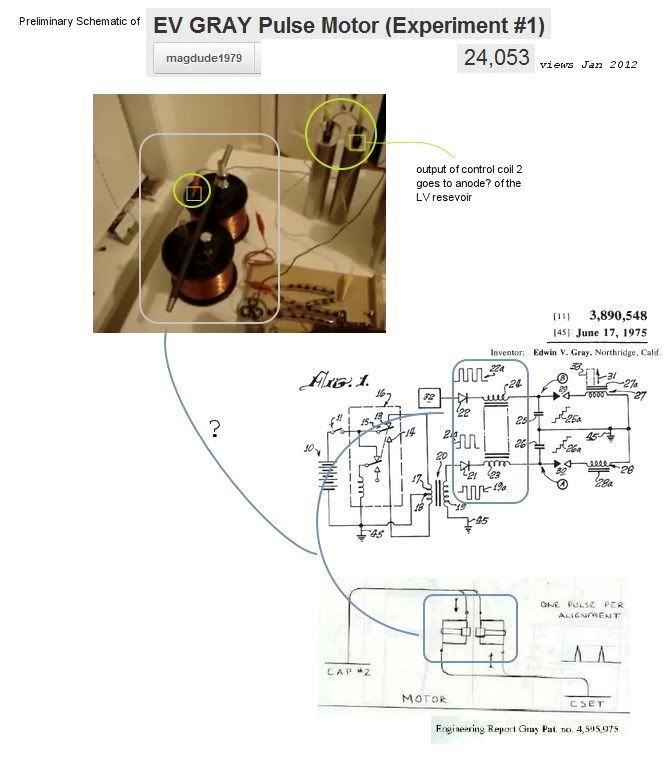
  • plasma discharge to power inductor

    Originally posted by geotron View Post
    There is a certain video in which a pulse motor is shown running with
    the E.Gray technology, without the use of a flyback-type coil. It
    appears they have mastered the technique. [ pulse motor experiment ]
    Few years ago, he said he agreed with my explanation. There is some schematic somewhere on his setup.

    Here is a demo I did later than his.
    Murakami-Gray Motor Replication - YouTube

    Here is the first demo ever shown utilizing this plasma effect to charge an inductor. Water Sparkplug | Plasma Ignition | With current restriction - YouTube
    I actually posted that early 2008 but youtube disabled one of my accounts and this was a repost months later.

    The reason I added a coil in series with this type of circuit was because I was thinking if I can limit current, I can have less electrons at the gap for H & O to recombine back into water moisture in order to have real thermal expansive power from exploding water with the plasma. I just happened to notice that the coil was jumping and I instantly saw a motor - the Ed Gray concept in my opinion. Anyway, you can see the sound gets quieter on the plasma plus the color changes.
    Last edited by Aaron; 01-15-2012, 08:44 PM.
    Sincerely,
    Aaron Murakami

    Books & Videos https://emediapress.com
    Conference http://energyscienceconference.com
    RPX & MWO http://vril.io

    Comment


    • ld vs tem

      Originally posted by lamare View Post
      And Eric told us exactly how to choose where in the system we want to get the aether to get our electrons moving, and where in the system we want the aether to stay away from our electrons:

      (i.e.: L.M.D. should be L.D., but that's just a detail)

      So, the trick seems to be to generate LM "no ohmic resistance" waves to get the aether going and to propagate that motion to where we want to use it (our coil), but to do it continuously instead of "disruptive".

      And then we need to convert our LD wave into a TEM wave around our coil in order to let it "drag into" the metallic, our coil.

      And that most of all means: matching of LD to TEM resonance frequencies in various parts of the system...
      Lamare,

      The flow over the wire has no ohmic resistance anyway. I see the distinction you're making between LD and TEM but the EFFECT of this is 100% identical to what Bearden points out with very conventional references.

      The dipole breaks the symmetry of the vacuum flux (or polarizes the aether) - to me these differences are insignificant because the end result is that the medium (aether) is simply ordered so that it can do work in a circuit. The flow (positive component of it) from the aether flowing over the space surrounding the wire (Heaviside flow) is moving from the positive terminal over the wire towards the negative terminal. That flow has no ohmic resistance. However, the part of this flow that is in contact with the surface of the wire "diverges" into the copper itself since it is positive and attracts the negatively charged electrons in the 3rd shell of the copper atom, which are the most loosely bound. Those electrons are then attracted towards the positive terminal. The are slow to move at a few inches per hour and this "Druid electron gas" is what the electron current is and how it is made.

      So your explanation of what Eric says is the LD is a flow over with no resistance and then there is TEM which "drags into the metallic" to get electrons moving, etc...

      With Bearden's explanation, the entire flow is the Heaviside Flow which happens to have 10 to the -13th amount of it that diverges or gets "dragged into the metallic" to cause electron current movement. Is that whole Heaviside flow the longitudinal component? Probably. Just because some of it gets dragged (diverged) into the metal, does that mean it is a completely different energy flow (transverse)?

      Eric says they are two different flows. Bearden says one flow, which part of it gets dragged into the metal.

      Besides the differences in the distinctions, the underlying effect of what is happening is no different between either one of their explanations.

      So far, I'm not seeing much of a difference between either one of their explanations.

      So from my interpretations, any electrical circuit, regardless of how it operates is never free of the "longitudinal" component that is flowing over the space surrounding the conductor.

      There are simply ways to have more, less or no drag of it into the metal.

      To get this longitudinal "wave" to be constant instead of disruptive, the Leedskalnin perpetual motion holder maintains just this - a very steady current at no voltage potential difference. Amps without volts or or wattless magnetic power. This is one example of constant flow without being disruptive.
      Sincerely,
      Aaron Murakami

      Books & Videos https://emediapress.com
      Conference http://energyscienceconference.com
      RPX & MWO http://vril.io

      Comment


      • The web search brought up some interesting websites also
        containing information on magdude's system. Without all
        the rest of what he has built in view, this coil system he
        has positioned next to the circuitry looks to be helping
        the motor. The true schematic still around?


        Engineering report Diagram by Gary Magratten
        Last edited by geotron; 01-16-2012, 10:17 AM.

        Comment


        • Over Unity Concepts at Nu Energy™ Research Archive has a patent application showing
          what could be one of the basic concepts behind how these systems work.


          Motor Report Directory

          Comment


          • gray circuit

            Originally posted by geotron View Post
            Over Unity Concepts at Nu Energy™ Research Archive has a patent application showing
            what could be one of the basic concepts behind how these systems work.


            Motor Report Directory
            That diagram has been discussed here before.

            There are not many fans left for Nu Energy. If you research, you'll see why.
            Sincerely,
            Aaron Murakami

            Books & Videos https://emediapress.com
            Conference http://energyscienceconference.com
            RPX & MWO http://vril.io

            Comment


            • After a bit of searching around there aren't a whole lot of results to
              base a decision on.

              Has the Figure 3 diagram been built, or otherwise proven not to work?

              Originally posted by Aaron View Post
              That diagram has been discussed here before.

              There are not many fans left for Nu Energy. If you research, you'll see why.

              Comment


              • simple diagram

                It has been a while since I've seen that but - a few years. Do you have the patent or app #?

                You have common grounds between everything as they should.

                You have a hv cap discharged through a coil when switch is contacted and that goes into the LV battery 7, which is of course a path to ground since it is a lower voltage positive with a common ground to the HV.

                In this setup, I'd have to see how that and when that switch controller comes into play. But it seems to put bother batteries in series for 24v if they're both 12v. It also puts that battery in series with the HV cap as well as in series with the diode. So when switch is closed, HV discharges and the low voltage current source is available to it through the common ground to mix. In principle, it seems to accomplish the mixing just like in the plasma ignition circuits.
                Sincerely,
                Aaron Murakami

                Books & Videos https://emediapress.com
                Conference http://energyscienceconference.com
                RPX & MWO http://vril.io

                Comment


                • The specification delves into some interesting tidbits, and while it
                  does not state the use of a spark gap it gives the impression of a
                  versatile system perhaps open to such modifications.

                  [ Edwin Gray's Patent Application ] at Nu Energy


                  Note : pdf from Nu Energy website is secured, upload to Scribd invalid,
                  link modified to original file at Nu Energy
                  Last edited by geotron; 01-18-2012, 07:58 AM.

                  Comment


                  • Ed Gray - Zetex

                    Thanks Geotron,

                    You can see how hard nuenergy tries to hide the reference #'s.

                    Here is the real thing: espacenet - Original document just hit the download button for a real copy.

                    That is one of the zetex ones. I think Mark McKay can give the history on it. When I see the diagram now, I see it a bit differently than I used to.

                    I'll check it out when I have time. Not sure what anyone else thinks about this one.
                    Sincerely,
                    Aaron Murakami

                    Books & Videos https://emediapress.com
                    Conference http://energyscienceconference.com
                    RPX & MWO http://vril.io

                    Comment


                    • Gray Circuit

                      Ok, I think it is just like I said earlier.

                      First, battery 1 charges the hv cap through the converter.

                      When HV cap is charged, switch 6 closes.

                      When switch 6 closes, that activates switch 8 which essentially puts the positive of battery 1 at the anode of diode 4.

                      As soon as that happens, the mechanical switch (which is what 6 looks like) conducts the HV over it towards 7 recovery battery and simultaneously, the LV + goes through the diode and follows the HV through the inductor over the switch and to battery 7. The current in battery 1 is obviously then going backwards through the circuit through the switch and through the inductor.

                      What this diagram shows is that Bedini is right about the diode placement being in reverse. Why?

                      When switch 6 is closed, the diode 4 is the same as the diode at the LV rod in the tube - it absolutely is because look at the battery 1, it's positive is connected to common ground which is exactly at the diode 4's anode. There is no difference from the tube setup. This diagram shows the truth.

                      Switch 6 closes and when battery 1 + is at the diode 4 anode, the hv from cap 3 has 2 paths. Towards the cathode of diode 4 or towards the inductor. Diode 4 shuts off and hv cap 3 can only go through inductor 5 and switch 6 to recovery batt 7. And LV battery mixes with the HV through the inductor.

                      I'm just thinking out loud here, but what this shows me in my opinion again, is that this shows the diode is supposed to be reversed at the LV rod in the tube like Bedini shows. I'm of course open to correction but this diagram is simply another variation of mixing the hv low current with lv and high current.

                      Look at battery 1. The negative is bypassed around the converter so that it shares common ground with the rest of the circuit - a current path to go backwards through the inductor when switch is closed. It appears switch 8 would just short battery 1 to itself but the positive I believe will go through the diode 4 and through the inductor.

                      It is spelled out in figure 1 & 2 in that application. The + of the battery 1 goes through switch 8 and then through diode 4!
                      Sincerely,
                      Aaron Murakami

                      Books & Videos https://emediapress.com
                      Conference http://energyscienceconference.com
                      RPX & MWO http://vril.io

                      Comment


                      • GB2030801a Ed Gray British application zetex

                        Here, I put up a direct download for everyone:

                        http://www.feelthevibe.com/free_ener...gb2030801a.pdf

                        And I don't know if the usage of "current" is proper. It looks like the description believes current flows in the direction of positive towards negative - so it looks like when you see "current" used in this application, it is actually the positive voltage potential is taking that route from battery 1 through 4, 5, 6, 7 and back around through diode 4.

                        It seems like at least, for now.
                        Last edited by Aaron; 01-18-2012, 08:58 AM.
                        Sincerely,
                        Aaron Murakami

                        Books & Videos https://emediapress.com
                        Conference http://energyscienceconference.com
                        RPX & MWO http://vril.io

                        Comment


                        • Gb2031665

                          Have you guys seen this one before?

                          espacenet - Original document

                          It was filed in 1978.

                          It has a very interesting schematic, which differs from the other ones I have seen:


                          Here, the grid of the triode is connected to the commutator, and there is another diode connected to the CSET...


                          Direct download link:
                          http://www.tuks.nl/pdf/Patents/Gray/...GB2031665A.pdf

                          More Gray Patents:
                          Directory contents of /pdf/Patents/Gray/

                          Comment


                          • Ed Gray circuit Zetex

                            Thanks Lamare,

                            I don't remember if I saw that one or not but it is another Zetex one.

                            You can see the overshoot gap 42 is not shorted like they are in the other patents.

                            Lines 81~83 states: "This voltage is produced by drawing a low current from a battery source 18 through the vibrator 20."

                            That appears to define Gray's terminology that he DOES believe current is moving from the positive of a battery, through the vibrator to the step up transformer. So this seems to be consistent with my perspective of the other diagram posted by Geotron in regards to Gray's reference of how current is moving.

                            Lines 101~106 states: "When the commutator current path through the thyratron is closed, current from the voltage source 18 is routed through a resistive element 30 and a low voltage anode 32. This causes a high energy discharge between the annodes within the conversion element 14."

                            So, we know 100% for sure that the + of the source battery 18 is available right there at the low voltage rod when tyratron is switched on - of course when commutator also connects the circuit.

                            @Lamare - The thyratron looks self triggered.

                            Q1 - When commutator is switched on, battery voltage is at the control grid. Is that actually sufficient to conduct between anode and cathode?

                            Q2 - Lets say grid is triggered and there is conductivity, will there be battery + potential available at the anode of the thyratron? The positive potential (that Gray calls current) is moving through commutator into cathode and out anode to be available at the LV rod.


                            Lines 91~96 states: "When the low-voltage anode 32 is connected to a source of current (battery positive), an arc is created in the spark gap designated 62 of the conversion element equivelant to the potential stored on the high-voltage anode, and the current available from the low-voltage anode.

                            What gray means by calling the HV potential is not only a reference to the voltage potential positive as in polarity even though it is + polarity, is it referred to as potential because it is sitting on the rod and not moving.

                            He calls the LV current from the battery current even though it is still positive polarity only because it is moving into the rod.

                            But the above underlined is telling the whole story. It appears that the entire Ed Gray methodology does simply revolve around the mixing of the HV low current with LV and higher current. It creates the plasma discharge as expected. When the commutator or thyratron is off, the only ground is over the 3rd point or gap to the grid through the inductor back to the battery + or over the overshoot gap to ground on the battery. My demos are exactly this - no different - with the exception of using diodes instead of a thyratron.

                            There is however something bogus in the diagram you posted. The HV cap 16 does NOT share a common ground with the LV source and therefore will not arc across when thyratron and commutator are on.
                            Sincerely,
                            Aaron Murakami

                            Books & Videos https://emediapress.com
                            Conference http://energyscienceconference.com
                            RPX & MWO http://vril.io

                            Comment


                            • In reference to GB2031665A,

                              This system shown in Figure 1 has the rectifiers on the LV anode such
                              that pull is generated on the cathodes of both the source and recovery
                              batteries; a reverse flow mechanism?

                              It seems highly different to the schematic of our systems, for which are
                              provided only a bank of enough diodes to block the HV pulse from the ignitor.

                              Might the items 26 and 28 instead be an SCR switch positioned before a
                              blocking rectifier? With a HV level not exceeding 5KV, it seems as though
                              the system would use two banks of five 1KV rectifiers, one for the item 28
                              and the other at 46.

                              It seems unclear what effect is attained by combining the fullwave
                              rectifier 24 with the halfwave 44 into the HV capacitor.

                              Comment


                              • common ground missing

                                Geotron,

                                I think fig 1 can't be properly understood if there is not a common ground the HV cap share with the LV source batteries.

                                If you only have HV coil discharge without a cap - it WILL jump the gap to the other rod because it is finding ground through the air - most people experience this with a simple ignition coil, which will spark to an object - a weak spark but a spark nevertheless because it finds ground through the air. But that is not enough to give this HV cap in this circuit a real discharge.

                                And I'd like to get Lamare's comments on the Thyratron - or Mark's if the LV + from the battery potential will be available at the rod if the thyratron is triggered and the LV goes into the cathode and out the annode - or is it directional, which would prevent the battery + from being available at the rod.
                                Sincerely,
                                Aaron Murakami

                                Books & Videos https://emediapress.com
                                Conference http://energyscienceconference.com
                                RPX & MWO http://vril.io

                                Comment

                                Working...
                                X