Announcement

Collapse
No announcement yet.

Gray Tube Replication

Collapse
X
 
  • Filter
  • Time
  • Show
Clear All
new posts

  • Opinions on New CEST Schematic

    Originally posted by Aaron View Post
    Geotron,

    And I'd like to get Lamare's comments on the Thyratron - or Mark's if the LV + from the battery potential will be available at the rod if the thyratron is triggered and the LV goes into the cathode and out the annode - or is it directional, which would prevent the battery + from being available at the rod.

    Dear Aaron,

    Here is my opinion on the operation/history of this circuit. Subject to change with additional data and/or experimental results.

    1. This circuit was in development in 1973 when John Bedini and Ron Cole called on E.V. Gray. It probably originated with Mr. Marvin Cole and really was not a bad concept if it had worked.

    2. Its purpose (speculated) was to replace the Thyratron/ Ignitron switching system (that was energy hungry and used on the early Pulse Motors) and used to discharged the anomalous energy in the storage capacitors through the opposing electromagnets in the engine. The other switching method used on the EMA4 was direct rotating contacts, but these didn't provide precise enough switching times to maximize the HP output.

    3. The circuit that generated the anomalous converted energy is not shown or disclosed in this circuit; except for the shunt diode and storage capacitor. I believe that the OU part of the circuit included the Floating Flux Field (FFF) but also several other required components (one being a spark gap) that were not disclosed in the patent.

    4. The Lion's share of the stored energy does not go through the CEST but rather through the sealed spark gap #42 (probably a commercial sealed hydrogen device). Only 10% or less of the switching energy goes through the CEST. See the reference Patent by Phinney which is listed on the Pulse Engine patent to see how this all works out. For those who are interested I have a 30 page paper on the subject to explain my speculated development of the various circuits that have been observed. The polarity of the series diode was an artifact error from Mr. Ron Cole’s notes. (But who knows)

    5. This CEST approach was only used on the EMA6 Free Energy Engine for about four months and then discarded. Mr. Hackenberger went back to the direct rotating contacts and got the system to work. There was something about a fixed arc that failed in this application. A stretched or dynamic arc seems to have worked much better. This was in 1976. The non-classical energy converters were hidden in those three each four terminal cans that were held out to be capacitors. Actually they were custom made passive circuits that processed the two opposing HV square waves from the power supplies. I'm sure that those cans also contained the storage device. It is rumored that it was a mica capacitor (to be verified)

    6. By 1979 Richard was back to using Thyratrons/Ignitrons. By this time the team was no longer working on automotive engines but rather irrigation pumps in which the energy overhead of the switching elements was no longer as much of a consideration.

    7. In 1980 Nelson Schlaft removed all of the Thyratrons in favor of a Zener Diode trigger approach for the Ignitrons. His retrofit (unknowingly) probably removed all of the circuit components that were generating the anomalous energy on the "Blue Engine". Or else the OU circuits (that looked like capacitor cans) were already removed. However, one of the dual two phase HV power supplied survived.

    8. From 1981 until his death E.V. Gray was attempting to sell licensing rights to this technology, but was in sore need of approved patents that would satisfy his investors. A re-work of the failed CEST approach seems to have filled the bill and would certainly not disclose anything about the real technology yet look exotic enough to be genuine.

    9. The only CEST type device built after 1976 was the single unit used just for bogus video advertisement production. In my opinion, attempting to figure out any of the details of the CEST circuit is not a good use of time or effort. The REAL non-classical circuit was never disclosed and perhaps never written down. It was too simple and to easy. No patent document could protect it for very long. It somehow takes the HV square wave pulses and converts them into "something" that can be stored in a capacitor device.

    Never the less, the idea of finding some kind of non-classical response in a CEST type of device (like what lamare is proposing) is still a possibility. I just don't think that is what Hackenberger was doing with it.

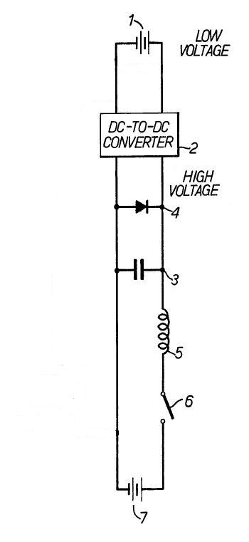
    The 80's British patent appears to me to be just a block diagram of the CEST circuit. I never paid much attention to it. However it does hint at the OU converter circuit as being "an inductive device". I'm sure that this circuit is indeed a general block diagram of the Free Energy Engines, but does not disclose enough detail to engineer the system. It does establish that the wet cell battery is a required component and not just a means to recapture the excitation energy. It also shows the importance of the shunt diode coupled with the storage capacitor.

    For now we need to know how that "inductive device" (that includes the FFF) was constructed and why it needs those HV square waves.

    Mark McKay

    Comment


    • thyratron

      Hi Mark,

      So far on the experiments I did, I couldn't see a different with or without the tube. If the tube was supposed to be filled with nitrogen that gets ionized and conductive to conduct the battery over to the grids then the nitrogen atoms recombine to stop that conductivity and shut if off abruptly - or something like that to increase impulse speed, then there may be something to it but I guess there is no evidence of that.

      The rotating spark gap is something I want to try on my ignition method with an inductor to see what a difference would be.

      As far as that thyratron, if it is as depicted in the patent diagrams in the conventional direction, can the battery + potential be available at the LV rod by moving backwards through the thyratron's cathode then to the anode when the it is triggered?
      Sincerely,
      Aaron Murakami

      Books & Videos https://emediapress.com
      Conference http://energyscienceconference.com
      RPX & MWO http://vril.io

      Comment


      • Originally posted by Aaron View Post
        Ok, I think it is just like I said earlier.

        First, battery 1 charges the hv cap through the converter.

        When HV cap is charged, switch 6 closes.

        When switch 6 closes, that activates switch 8 which essentially puts the positive of battery 1 at the anode of diode 4.

        As soon as that happens, the mechanical switch (which is what 6 looks like) conducts the HV over it towards 7 recovery battery and simultaneously, the LV + goes through the diode and follows the HV through the inductor over the switch and to battery 7. The current in battery 1 is obviously then going backwards through the circuit through the switch and through the inductor.

        What this diagram shows is that Bedini is right about the diode placement being in reverse. Why?

        When switch 6 is closed, the diode 4 is the same as the diode at the LV rod in the tube - it absolutely is because look at the battery 1, it's positive is connected to common ground which is exactly at the diode 4's anode. There is no difference from the tube setup. This diagram shows the truth.

        Switch 6 closes and when battery 1 + is at the diode 4 anode, the hv from cap 3 has 2 paths. Towards the cathode of diode 4 or towards the inductor. Diode 4 shuts off and hv cap 3 can only go through inductor 5 and switch 6 to recovery batt 7. And LV battery mixes with the HV through the inductor.

        I'm just thinking out loud here, but what this shows me in my opinion again, is that this shows the diode is supposed to be reversed at the LV rod in the tube like Bedini shows. I'm of course open to correction but this diagram is simply another variation of mixing the hv low current with lv and high current.

        Look at battery 1. The negative is bypassed around the converter so that it shares common ground with the rest of the circuit - a current path to go backwards through the inductor when switch is closed. It appears switch 8 would just short battery 1 to itself but the positive I believe will go through the diode 4 and through the inductor.

        It is spelled out in figure 1 & 2 in that application. The + of the battery 1 goes through switch 8 and then through diode 4!

        I think the basic principle of this circuit can be reduced to this:


        When the switch closes after the HV cap has been charged, what happens is:

        1) You get a (HF) transient, a sudden (large!) change of voltage on one of the terminals of the coil, with an extremely short switching time, because of the use of a mechanical switch which also forms a spark gap just moments before closing.

        2) This transient gives you a shockwave, generating a wave with an extreme dE/dt propagating (with the speed of light or so) along your coil windings, which on its turn energizes the coil by generating a magnetic field along Maxwell's extension of Ampere's law:

        Ampère's circuital law - Wikipedia, the free encyclopedia

        3) Current starts flowing (within nano-seconds or so after closing the switch, but *after* the transient shock wave already energized the coil), whereby the HV cap discharges trough the coil towards the battery.

        4) Now the coil has been energized by two sources (transient wave and HV discharge) and therefore the (B)EMF will contain more energy than expected when considering only the energy contained in the HV cap.

        5) (B)EMF maintains the current in the direction it had before, trying to discharge the HV cap. When the voltage on the HV cap becomes 0 V, the diode prevents further discharge of the cap and the coil continues to charge the battery trough the diode. This way, all the (B)EMF energy contained is used to charge the battery.


        And if this is the basis principle, then you would expect problems arising with the switch, especially when you scale this up to an engine delivering considerable horsepower. The contacts of the switch would wear-out pretty fast, resulting in problems with timing, etc. And then you may end up looking at special high-current spark gaps, which you somehow trigger, which may also be what the CSET is for, as I suggested earlier.

        Comment


        • thyratron

          Lamare,

          All the articles, patents, etc... have always said the "key" is in mixing DC with "static" or HV - as the basic principle. Removing the DC mixing with the HV will cause the HV cap to discharge much slower.


          Whatever the case may be, can you comment on this?

          "As far as that thyratron, if it is as depicted in the patent diagrams in the conventional direction, can the battery + potential be available at the LV rod by moving backwards through the thyratron's cathode then to the anode when the it is triggered?"


          [IMG]file:///C:/DOCUME%7E1/MASTER%7E1.MON/LOCALS%7E1/Temp/moz-screenshot.png[/IMG][IMG]file:///C:/DOCUME%7E1/MASTER%7E1.MON/LOCALS%7E1/Temp/moz-screenshot-1.png[/IMG]
          Sincerely,
          Aaron Murakami

          Books & Videos https://emediapress.com
          Conference http://energyscienceconference.com
          RPX & MWO http://vril.io

          Comment


          • The E. V. Gray Block Diagram - Comments

            Dear lamare,

            Yes, you have pretty well described the discharge part of the Gray circuit.

            In an analysis of the "Popping Coil" Demo apparatus the series location of the switching device and the opposing electromagnets are reversed. I’m not sure if it makes a whole lot of difference either way.

            I have experiment with this circuit several times. When the switch closes the current through the overall series loop increases in a half since wave form according to the RLC formula. Once the peak current is established, or first zero crossing of the capacitor voltage, the diode conducts and cuts the capacitor completely out of the circuit until all the energy is dissipated. From here on, the current decays at an exponential rate according to the LR formula. There is no resonance in this circuit. It is a unidirectional current pulse through the inductor. The overall pulse width is determined by the size of the capacitor. The peak current is determined by the initial charge on the capacitor. Of course both of these parameters are related to the size of the inductor. Even if the circuit would ring due to low series damping resistance it will not happen when a diode is involved.

            This is a typical Mass Driver circuit. To get the best transfer of energy from the drive coil to the projectile coil the L and C parameters need to be adjusted according to the mass of the projectile.

            On the subject of transients in this circuit: I don't see them and I have a fast scope (300 MHz). The large capacitor (I use a 5 uF at 5 kV) just sucks up any fast change in voltage across its terminals.

            Now on to additional speculations concerning this layout from my WAG department:

            1. The Wet Cell Battery is not there to be charged. It is there because it is the means to draw the stored anomalous particles out of the storage capacitor. Hackenberger was having serious problems with these batteries exploding. He certainly didn't need the few Joules of energy that could be harvested from this approach with a COP of 275 resulting from non-classical torque. The back end battery is a fundamental component in this technology. Gray was probably attempting to patent this concept to some extent in the British application. If so, then it was a weak attempt since he didn't specify it in his claims.

            1-a. Also the power level of the Engine was controlled by what voltage level was used to draw the non-classical particles from the storage capacitors. The EMA4 and EMA6 tapped the wet cell batteries at 6 locations. We know very little about the physics of these proposed non-classical particles. Perhaps not all of them were utilized in each discharge so that a little "Cold Electricity" could go a long ay and be spread out over several power strokes. We just don't know.

            2. The storage capacitor contains both classical electrons on the negative plate and the non-classical positive particles on the positive plate. So a voltage difference could be measured with an analog VOM, but the measurement process probably contaminates the concentration of the anomalous particles - to be verified. An electrostatic meter with its 10**15 Ohms resistance is probably a better way to go.

            3. The non-classical energy conversion takes place in the Block labeled as the DC/DC converter. True, 90% of that is a classical DC/DC converter but the last 10% of the components make the big difference.

            4. The CEST was designed to take the place of the switch. Direct rotary switching was used also. In the end Thyratrons/Ignitrons were used. To get the most torque out of a repulsion pulse motor, timing is everything. When the electromagnets are fired there are two energy flows. The classical electron flow is seeking a path to the storage capacitor and the non-classical particles are seeking a path to the negative terminal of the wet cell battery (single wire flow). The non-classical particles provide a heck of a lot more magnetic flux than the electrons.

            5. This block diagram circuit only shows 1/2 of the mirror image of the required other half of the total circuit. To get the maximum COP from this technology two pulse systems are designed to work against each other. Again, a wet cell battery is required (the front end battery) to attract the non-classical positive particles into the storage capacitors. This is a one wire process also.

            6. Energy Recovery. What is not shown in any of the circuits discussed so far is a very large classical recovery of current that is returned to the front end battery to be processed again through the DC/DC converter. This feedback current flow was described and measured by Mr. Hackenberger in his early Engineering reports. The result is to greatly reduce the current demand on the Front End battery. Some of the assumed features of the pulse motor are responsible for this.

            7. There is also some evidence that the very act of blasting the two opposing coils apart was also used to increase the magnitude of the reaction. This has to do with the oxygen in the arc and the dynamic gap that Richard had to fall back on. This implies that an arc composed of non-classical particles and classical current makes for one big pop, not unlike what Arron describes in the mixing of energy sources in a plasma discharge. I suspect that it was this part of the process that was somehow harvested and recycled.

            8. The block diagram being discussed is simple, the overall Free Energy Engine was a complex machine.

            Mark McKay

            Comment


            • Originally posted by Aaron View Post
              Thanks Lamare,

              I don't remember if I saw that one or not but it is another Zetex one.

              You can see the overshoot gap 42 is not shorted like they are in the other patents.

              Lines 81~83 states: "This voltage is produced by drawing a low current from a battery source 18 through the vibrator 20."

              That appears to define Gray's terminology that he DOES believe current is moving from the positive of a battery, through the vibrator to the step up transformer. So this seems to be consistent with my perspective of the other diagram posted by Geotron in regards to Gray's reference of how current is moving.

              Lines 101~106 states: "When the commutator current path through the thyratron is closed, current from the voltage source 18 is routed through a resistive element 30 and a low voltage anode 32. This causes a high energy discharge between the annodes within the conversion element 14."

              So, we know 100% for sure that the + of the source battery 18 is available right there at the low voltage rod when tyratron is switched on - of course when commutator also connects the circuit.

              @Lamare - The thyratron looks self triggered.

              Q1 - When commutator is switched on, battery voltage is at the control grid. Is that actually sufficient to conduct between anode and cathode?

              Q2 - Lets say grid is triggered and there is conductivity, will there be battery + potential available at the anode of the thyratron? The positive potential (that Gray calls current) is moving through commutator into cathode and out anode to be available at the LV rod.


              Lines 91~96 states: "When the low-voltage anode 32 is connected to a source of current (battery positive), an arc is created in the spark gap designated 62 of the conversion element equivelant to the potential stored on the high-voltage anode, and the current available from the low-voltage anode.

              What gray means by calling the HV potential is not only a reference to the voltage potential positive as in polarity even though it is + polarity, is it referred to as potential because it is sitting on the rod and not moving.

              He calls the LV current from the battery current even though it is still positive polarity only because it is moving into the rod.

              But the above underlined is telling the whole story. It appears that the entire Ed Gray methodology does simply revolve around the mixing of the HV low current with LV and higher current. It creates the plasma discharge as expected. When the commutator or thyratron is off, the only ground is over the 3rd point or gap to the grid through the inductor back to the battery + or over the overshoot gap to ground on the battery. My demos are exactly this - no different - with the exception of using diodes instead of a thyratron.

              There is however something bogus in the diagram you posted. The HV cap 16 does NOT share a common ground with the LV source and therefore will not arc across when thyratron and commutator are on.

              I don't know too much about vacuum tubes. They don't teach those at Universities anymore...

              Wikipedia has some info on the thyratron:
              Thyratron - Wikipedia, the free encyclopedia

              A thyratron is a type of gas filled tube used as a high energy electrical switch and controlled rectifier. Triode, tetrode and pentode variations of the thyratron have been manufactured in the past, though most are of the triode design. Because of the gas fill, thyratrons can handle much greater currents than similar hard vacuum valves/tubes since the positive ions carry considerable current.

              [...]

              A typical hot-cathode thyratron uses a heated filament cathode, completely contained within a shield assembly with a control grid on one open side, which faces the plate-shaped anode. When positive voltage is applied to the anode, if the control electrode is kept at cathode potential, no current flows. When the control electrode is made slightly positive, gas between the anode and cathode ionizes and conducts current.

              [...]

              Both hot- and cold-cathode versions are encountered. A hot cathode is at an advantage, as ionization of the gas is made easier; thus, the tube's control electrode is more sensitive. Once turned on, the thyratron will remain on (conducting) as long as there is a significant current flowing through it. When the anode voltage or current falls to zero, the device switches off.

              [...]

              Thyratrons have been replaced in most low and medium-power applications by corresponding semiconductor devices known as thyristors (sometimes called silicon-controlled rectifiers, or SCRs) and triacs. However, switching service requiring voltages above 20 kV and involving very short risetimes remains within the domain of the thyratron. Variations of the thyratron idea are the krytron, the sprytron, the ignitron, and the triggered spark gap, all still used today in special applications.

              Here is some info on diodes and triodes:
              Valve Diodes and Triodes

              It says that the reverse current of such a device is almost zero:

              When we apply a voltage to make the anode positive with respect to the cathode we attract the electrons in the vacuum space towards the anode, and push them away from the cathode. This has the effect of making it easier for electrons to reach the anode. It also tends to reduce the density of electrons near the cathode, making it easier for more to ‘boil off’ the cathode. The result is that when we apply a potential difference this way around we tend to increase the rate at which electrons flow from cathode to anode. Thus, making the anode positive relative to the cathode increases the current flow. This sign of applied potential is called “Forward Bias”.

              When we apply a voltage the other way around, and make the anode negative with respect to the cathode we repel the electrons in the vacuum space away from the anode, and make it harder for them to escape the cathode. Since the anode isn’t hot, it does not tend to release any electrons itself. The result is that when we apply a potential difference this way around we tend to make it even harder for any electrons to cross the vacuum space. The current flow is therefore almost zero. This sign of applied potential is called “Reverse Bias”.
              And in this pdf you can see that a triode can be used as a diode:
              http://www.nikhef.nl/~h73/kn1c/prakt...rim/4_1_10.pdf

              However, for use as a diode, the grid would have to be connected to the anode instead of the (heated?) cathode.

              Here's also some interesting info:
              6JD5 Forward grid bias

              It is also possible to operate a tube in a condition called inverted operation:

              Inverted Triodes - The 6AS7/6080 Family
              Inverted Tube Operation

              It is possible to operate a tube in a condition called inverted operation. In this mode, the signal is applied to a NEGATIVELY BIASED PLATE, (acting as the grid), and the "amplified" signal is taken from the positively biased grid (acting as the plate). Since the physical plate is positioned OUTSIDE of the grid, a much larger change in the negative bias is required to affect the grid (acting as plate). Thus, the MU is much lower. In fact, the effective MU is approximately the inverse of the normal MU of the tube. Thus, a device with a "forward" MU of 10 will act like a device with a MU of approximately 1/10, and a device with a MU of 4 will act as a device with a MU of approximately ¼.

              [...]

              There are two benefits of this operation. The first is the plate resistance is substantially lower (which can aid in driving low impedance loads), and the input capacitance (input is connected to the plate, remember) is much lower. There is also essentially no Miller effect capacitance to worry about, as the voltage gain is much lower than unity. Notice that the device still develops power gain, as the input impedance is very high and the output impedance is very low.
              I will study some of this and think about this some more.

              Comment


              • experiments with sparks & arcs

                Hello everyone, after experimenting for a while here are the results that i have, I use 1mm diameter copper wire as electrodes.
                1. Sparks have a purple based color, this comes from ionized air (nitrogen & oxygen). This color is based from electric current : low current will produce purple, bigger current will make whiter & brighter spark.
                2. Arcs from copper electrodes have a green based color, just like Aaron's green arc. This is also have a color based from electric current. The green arc only manifest if during arcing process the electrode is hot enough to vaporize and copper ions get activated by electric current.
                3. To make a spark (without arc) you need to make the electric current goes as quick as possible, without heating the electrodes. This can be made by using a very low ESR capacitor that short-circuited without any resistance.
                4. On the contrary, to make an arc you need to make the current goes as slow as possible to heat enough the electrodes. This can be made by using ordinary electrolyte capacitor (high ESR) that short-circuited with some resistance.

                Wicaksono

                Comment


                • Originally posted by Spokane1 View Post
                  Dear lamare,

                  Yes, you have pretty well described the discharge part of the Gray circuit.

                  In an analysis of the "Popping Coil" Demo apparatus the series location of the switching device and the opposing electromagnets are reversed. I’m not sure if it makes a whole lot of difference either way.

                  I have experiment with this circuit several times. When the switch closes the current through the overall series loop increases in a half since wave form according to the RLC formula. Once the peak current is established, or first zero crossing of the capacitor voltage, the diode conducts and cuts the capacitor completely out of the circuit until all the energy is dissipated. From here on, the current decays at an exponential rate according to the LR formula. There is no resonance in this circuit. It is a unidirectional current pulse through the inductor. The overall pulse width is determined by the size of the capacitor. The peak current is determined by the initial charge on the capacitor. Of course both of these parameters are related to the size of the inductor. Even if the circuit would ring due to low series damping resistance it will not happen when a diode is involved.

                  This is a typical Mass Driver circuit. To get the best transfer of energy from the drive coil to the projectile coil the L and C parameters need to be adjusted according to the mass of the projectile.

                  On the subject of transients in this circuit: I don't see them and I have a fast scope (300 MHz). The large capacitor (I use a 5 uF at 5 kV) just sucks up any fast change in voltage across its terminals.

                  Now on to additional speculations concerning this layout from my WAG department:

                  1. The Wet Cell Battery is not there to be charged. It is there because it is the means to draw the stored anomalous particles out of the storage capacitor. Hackenberger was having serious problems with these batteries exploding. He certainly didn't need the few Joules of energy that could be harvested from this approach with a COP of 275 resulting from non-classical torque. The back end battery is a fundamental component in this technology. Gray was probably attempting to patent this concept to some extent in the British application. If so, then it was a weak attempt since he didn't specify it in his claims.

                  1-a. Also the power level of the Engine was controlled by what voltage level was used to draw the non-classical particles from the storage capacitors. The EMA4 and EMA6 tapped the wet cell batteries at 6 locations. We know very little about the physics of these proposed non-classical particles. Perhaps not all of them were utilized in each discharge so that a little "Cold Electricity" could go a long ay and be spread out over several power strokes. We just don't know.

                  2. The storage capacitor contains both classical electrons on the negative plate and the non-classical positive particles on the positive plate. So a voltage difference could be measured with an analog VOM, but the measurement process probably contaminates the concentration of the anomalous particles - to be verified. An electrostatic meter with its 10**15 Ohms resistance is probably a better way to go.

                  3. The non-classical energy conversion takes place in the Block labeled as the DC/DC converter. True, 90% of that is a classical DC/DC converter but the last 10% of the components make the big difference.

                  4. The CEST was designed to take the place of the switch. Direct rotary switching was used also. In the end Thyratrons/Ignitrons were used. To get the most torque out of a repulsion pulse motor, timing is everything. When the electromagnets are fired there are two energy flows. The classical electron flow is seeking a path to the storage capacitor and the non-classical particles are seeking a path to the negative terminal of the wet cell battery (single wire flow). The non-classical particles provide a heck of a lot more magnetic flux than the electrons.

                  5. This block diagram circuit only shows 1/2 of the mirror image of the required other half of the total circuit. To get the maximum COP from this technology two pulse systems are designed to work against each other. Again, a wet cell battery is required (the front end battery) to attract the non-classical positive particles into the storage capacitors. This is a one wire process also.

                  6. Energy Recovery. What is not shown in any of the circuits discussed so far is a very large classical recovery of current that is returned to the front end battery to be processed again through the DC/DC converter. This feedback current flow was described and measured by Mr. Hackenberger in his early Engineering reports. The result is to greatly reduce the current demand on the Front End battery. Some of the assumed features of the pulse motor are responsible for this.

                  7. There is also some evidence that the very act of blasting the two opposing coils apart was also used to increase the magnitude of the reaction. This has to do with the oxygen in the arc and the dynamic gap that Richard had to fall back on. This implies that an arc composed of non-classical particles and classical current makes for one big pop, not unlike what Arron describes in the mixing of energy sources in a plasma discharge. I suspect that it was this part of the process that was somehow harvested and recycled.

                  8. The block diagram being discussed is simple, the overall Free Energy Engine was a complex machine.

                  Mark McKay
                  Dear Mark,

                  Why the postulation of the existence of some kind of "positive particles" before considering phenomena we already know to exist: EM waves (and also longitudinal dielectric waves, for which we also have quite strong indications that these also exist) which propagate at the speed of light (or more) *and* can be connected very nicely to Maxwell's extension of Gauss' law?


                  You may also want to take a look at this video posted at a.o. Eric Dollards yahoo group:

                  Hello everybody, I have posted a new video showing the propagation of Direct Current through the natural medium, air. I investigate some of the properties and claim Tesla was making by suggesting this mechanism as a way to transfer energy. It is also a good way to see how directional DC sparks looks like compared to AC sparks. That is what we need to aim for when we energize our systems.

                  Propagation of Direct Current Through space - YouTube

                  Thomas

                  Another point to think about is the bandwidth of the transient. We are looking at a spark gap that suddenly breaks down. Now I agree that the sudden break-down is not the same as an arc, but the fact that spark gap transmitters have been shown to operate at frequencies as high as 60 GHz does suggest that a scope with a bandwidth of "just" 300 MHz may very well be far from sufficient to measure the transient:

                  J.C. Bose: 60 GHz in the 1890s

                  Just one hundred years ago, J.C. Bose described to the Royal Institution in London his research carried out in Calcutta at millimeter wavelengths. He used waveguides, horn antennas, dielectric lenses, various polarizers and even semiconductors at frequencies as high as 60 GHz; much of his original equipment is still in existence, now at the Bose Institute in Calcutta. Some concepts from his original 1897 papers have been incorporated into a new 1.3-mm multi-beam receiver now in use on the NRAO 12 Meter Telescope.
                  And also consider what they use Marx generators for:

                  Marx generator - Wikipedia, the free encyclopedia
                  A bank of 36 Marx generators is used by Sandia National Laboratories to generate X-rays in their Z Machine.
                  X-ray - Wikipedia, the free encyclopedia
                  X-radiation (composed of X-rays) is a form of electromagnetic radiation. X-rays have a wavelength in the range of 0.01 to 10 nanometers, corresponding to frequencies in the range 30 petahertz to 30 exahertz (3×10¹⁶ Hz to 3×10¹⁹ Hz) and energies in the range 120 eV to 120 keV. They are shorter in wavelength than UV rays and longer than gamma rays. In many languages, X-radiation is called Röntgen radiation, after Wilhelm Conrad Röntgen, who is usually credited as its discoverer, and who had named it X-radiation to signify an unknown type of radiation.[1] Correct spelling of X-ray(s) in the English language includes the variants x-ray(s) and X ray(s).[2] XRAY is used as the phonetic pronunciation for the letter x.
                  Of course, these X-Rays are not generated by the spark gap directly in this Z-Machine, but it is clear that we are most likely looking at a phenomenon with a bandwidth of several GHz.

                  Comment


                  • Thyratrons in the E. V. Gray Technology

                    Dear lamare,

                    You must have spent all evening doing all that technical research on Thyratrons. I certainly appreciate your efforts. It is work like this that will help solve this import mystery.

                    The attached photo is from an old 50's - 60's spot welder. It employs the very same Ignitorn that Gray used and is fired by 2 Thyratrons. For a spot welder the repetition rate is very low. At most 3 Hz. and more typically .5 Hz.

                    The GE Gl-7171 Ignitron is the blue can on the left. The two large vacuum tubes in the center are the Thyratrons. This appears to be a cascade approach with the smaller capacity Thyratron (center) driving the larger capacity Thyratron (left of center). The Vacuum tube in the right rear is a HV rectifier with a PIV of about 2500 VDC. The smaller vacuum tube on the right is most likely a Triode.

                    These are the kinds of components that I would expect that Nelson Schlaft was confronted with when he was hired to "Make the Motor's Work" in late 1980.

                    There were not a lot of cheap solutions to switch HV at the rate and power levels that Hackenberger needed in the 70's (thus the need for the CEST approach). However, these kinds of devices were plentiful on the surplus market. For Hackenberger in the late 70's it didn't really matter if the thyratrons would not be used in the final application. He was attempting to improve the Free Energy Engine and was focusing his engineering efforts in other more productive areas. This part of the circuit could easily be upgraded with newer components in future versions.

                    To me this strongly hints that the non-classical conversion process does not take place in these components. To me the CEST was an attempted replacement for the Ignitrons, but didn't work well enough. Therefore the CEST was not the seat of the novel Free Energy creation. But this is just my opinion and not fact.

                    For me I'm using mechanical contactors to discharge my storage capacitor for single shot experiments. When I get to the point where I need higher repetition rates I going to upgrade to HV SCR's, provided that they can effectively switch the novel energy particles that I speculate will be stored in the capacitor.

                    Mark McKay
                    Attached Files

                    Comment


                    • The speculated positive particles

                      Dear lamare,

                      On the subject of speculated anomalous positive particles as opposed to a wave process comes from Dr. Tesla's patent documents.

                      In his discussion of this theory of operation he refers to a kind of positive particle that has mass. It can be stored in a Mica capacitor and is attracted by "'negative electricity" - like what can be found from a wet-cell battery or the earth ground. Of course the earth ground was a lot cheaper.

                      What is important is that this described energy flow takes place in a single wire configuration.

                      I don't believe that waves have mass nor can they be stored. We know from the testimony of observers of the E. V. Gray technology that this anomalous energy took some time to collect and we are lead to believe that it was stored in a capacitor like device.

                      I just can't come up with a model for a wave process that would fit these requirements. But don't let me rain on your parade. If you favor a wave process then great. I could be very wrong. If your hard work proves to be the more correct approach then I will gladly chuck all of my WAG's in a heartbeat.

                      If you would like the specific Tesla patent references I shall be glad to dig them up. (The book is on my living room reading table at home).

                      Again the WAG department:

                      The whole Marvin Cole conversion circuit with the FFF and its dual circuit construction is appearing to be just like Dr. Tesla's Transmitter/Receiver system with the middle men (the HV secondary’s) removed. The non-classical action takes place in the Tesla Coil primary when interacting with a suitable dielectric. For now the primary is in the FFF.

                      The system works in a push-push fashion. On alternate cycle’s one coil of the FFF acts like the primary of a Tesla transmitter while the other acts as a receiver. The non-classical particles are generated due to the speed of the disruptive discharge and the properties of the dielectric (used as cable insulation). An external applied magnetic field is needed to shepherd these particles into the storage capacitor where they are "pinned" by the attraction of the electrons on the negative terminal of the battery.

                      I'm sure there are several additional tricks that are needed. One of them is the frequency of the disruptive discharge. It has to match the response of the dielectric involved. This can range from 30 to 100 kHz.

                      Another possibility is that the dielectric used has to have been previously processed to become an electret. This can be done to the FFF cable. In Dr. Tesla's applications he seems to have done this to both his secondaries and capacitors. But this has only been hinted at and not directly disclosed.

                      I have no doubt that almost all of Eric Dollard’s work is valid and that longitudinal dielectric waves exist. I’m sure that this will all fit into Maxwell’s extension of Gauss’ law and eventually be accepted. I just don’t see how this model fits well with the observed E.V. Gray technology – at least from my analysis of the operation and the observed hardware involved. Again I could be wrong.

                      So far as I can see Eric’s work is all about a novel kind of faster than light mode of energy propagation. Great, now where is the energy gain?

                      Mark McKay

                      Comment


                      • green plasma

                        Originally posted by Wicaksono View Post
                        Hello everyone, after experimenting for a while here are the results that i have, I use 1mm diameter copper wire as electrodes.
                        1. Sparks have a purple based color, this comes from ionized air (nitrogen & oxygen). This color is based from electric current : low current will produce purple, bigger current will make whiter & brighter spark.
                        2. Arcs from copper electrodes have a green based color, just like Aaron's green arc. This is also have a color based from electric current. The green arc only manifest if during arcing process the electrode is hot enough to vaporize and copper ions get activated by electric current.
                        3. To make a spark (without arc) you need to make the electric current goes as quick as possible, without heating the electrodes. This can be made by using a very low ESR capacitor that short-circuited without any resistance.
                        4. On the contrary, to make an arc you need to make the current goes as slow as possible to heat enough the electrodes. This can be made by using ordinary electrolyte capacitor (high ESR) that short-circuited with some resistance.

                        Wicaksono
                        Hi Wicaksono,

                        I'd like to say that with my method, the plasma ball is green with every single metal I have used - copper, brass, stainless steel, rusty iron nails, etc... without the inductor, with the same metals and circuit, the plasma is very white - just by adding the inductor, it turns green.
                        Sincerely,
                        Aaron Murakami

                        Books & Videos https://emediapress.com
                        Conference http://energyscienceconference.com
                        RPX & MWO http://vril.io

                        Comment


                        • triode - thyratron

                          Good find Lamare!

                          I blew out some thyristors in some experiments early on after Magratten published his experiments - that was before I knew what was going on. I still don't necessarily know what is going on but I think I'm in the right direction. lol

                          It seems the self triggering 'could' come from the cathode since there is a positive voltage from the battery there. But with the positive voltage also there from the battery at the cathode, it would seem to mean that there is no ability for current to flow through the triode.

                          Of course I'm using the patent reference of how the triode is depicted.

                          Here is my old comparison for reference:


                          Now just like how a regular diode works, if the positive voltage is on the cathode of a diode, it keeps it shut off and in non-conductive mode. The positive voltage has to be at the anode for that voltage to be available at the cathode - minus the voltage drop of course.

                          So on the triode, even if the grid is triggered, with the battery positive potential at the cathode as shown on the right side of the above image, that seems to mean it is reverse biased and in non-conductive mode just like a diode. Therefore, it appears that the battery potential is not going to be available at the anode and therefore the HV cap sees no path to ground and will not even jump the gap to the LV rod.

                          The HV can of course jump if it sees path to ground through the triode but seeing that the condition of having the triode forward biased first is a requirement that has to be met first, I don't it working 'yet'.

                          And again from the description in the patents, the explanation is that Gray sees the positive from the battery going from the battery, through the commutator, towards the LV rod - only calling it current because it is moving and not a reference to electron current moving from neg to pos.

                          "Lines 81~83 states: "This voltage is produced by drawing a low current from a battery source 18 through the vibrator 20."

                          That appears to define Gray's terminology that he DOES believe current is moving from the positive of a battery, through the vibrator to the step up transformer. So this seems to be consistent with my perspective of the other diagram posted by Geotron in regards to Gray's reference of how current is moving.

                          Lines 101~106 states: "When the commutator current path through the thyratron is closed, current from the voltage source 18 is routed through a resistive element 30 and a low voltage anode 32. This causes a high energy discharge between the annodes within the conversion element 14."

                          So, we know 100% for sure that the + of the source battery 18 is available right there at the low voltage rod when tyratron is switched on - of course when commutator also connects the circuit.
                          "

                          So with this evidence, we know that the battery positive has to be at the LV rod for the HV cap to actually discharge across the gap - and experimentation proves this without a doubt.

                          If the triode in the reversed bias mode does not allow the battery potential to be at the LV rod when switched on, then this would be strong evidence, if not proof, that the triode direction in the patent is wrong and that the way Bedini-Cole show it has always been correct. I find it difficult to believe that they got the direction of it wrong after actually examining it. Anything is possible but it is only with the diode in that direction that at least in my experiments that I get anything unusual - the plasma discharge with an accelerated discharge speed of the capacitor and not just a regular capacitive discharge.

                          Of course the bottom line is to just do the simple experiment with a triode as shown in the patent to see if the battery voltage is available at the anode when the control grid is triggered. If so, then it is possible that that triode placement is an honest depiction but even if it works - there is no unconventional result that arises from this placement - my prediction.

                          I've done this kind of experiment with the plasma circuits with diodes. When battery or LV cap potential is on the cathode, it just keeps the diode in non-conducting mode and the HV will not see path to ground.

                          There is an exception to this that would make it appear that the triode/diode is in conduction mode and that is by simply having something conductive hear the HV output from the ignition coil. If you pulse a HV coil for example and have any piece of copper for example, it will give a feeble little spark to that metal since it is finding path to ground through the air. But that of course is of course 15-25 kv at minimum in those coils and not 2kv-5kv in a capacitor, which probably wouldn't do that so I would guess using a HV cap in this range will not spark over unless the triode/diode is truly in full conduction mode.

                          I'll have to look more into that inverted mode on the thyratron. The only experience I have with tubes is with pentodes for some special amplifiers I built. They work the same way but all I needed to know is how to connect them so I didn't need to know their operating theory.

                          Basic little triode diagram:


                          Lamare, Mark or anyone, what about an SCR? If it is triggered and there is a 12v batter voltage on the cathode, will that voltage be available at the anode? It is basically our triode equivelant isn't it?
                          Sincerely,
                          Aaron Murakami

                          Books & Videos https://emediapress.com
                          Conference http://energyscienceconference.com
                          RPX & MWO http://vril.io

                          Comment


                          • reverse bias triode

                            Lighthouse Electric Vacuum Tube Tutorial

                            Good simple tutorial on the triodes.

                            Here is a reverse bias example with positive potential at the cathode, it is in non-conductive mode and no current can flow.


                            Of course this example shows a full connection with anode going back to ground and with the Gray patents, the anode is left unconnected with only a gap to the HV potential.

                            Perhaps the HV potential at the HV rod over the gap is enough to attract the electrons to the anode plate in order to be conductive. If that can over come the attraction of electrons towards the cathode where the battery + is at, then maybe it can be conductive and the HV cap can discharge across. I can only see something like this working if there is common ground like the common patents show - that Zetex patent does not show a common ground with the HV side.
                            Sincerely,
                            Aaron Murakami

                            Books & Videos https://emediapress.com
                            Conference http://energyscienceconference.com
                            RPX & MWO http://vril.io

                            Comment


                            • Originally posted by Spokane1 View Post

                              So far as I can see Eric’s work is all about a novel kind of faster than light mode of energy propagation. Great, now where is the energy gain?

                              Mark McKay
                              You may want to watch this video too:
                              MIT Physics Demo -- Dissectible Capacitor - YouTube

                              And then watch the one I posted above, about Tesla's DC current propagating trough space:
                              Propagation of Direct Current Through space - YouTube

                              Now head over to Wheatstone's experiment:
                              http://www.tuks.nl/pdf/Reference_Mat...ic%20Light.pdf

                              A very interesting experiment, that could pretty easily be repeated with modern electronics. As far as I understand, he basically discharges a HV cap trough a spark gap into a common connection on two long wires, which both end on two spark gaps to ground (negative pole of the HV cap). All three spark gaps were placed before a rotating mirror, so he could measure the timing of the three sparks. The same principle (rotating mirror) was later used to measure the speed of light, BTW.

                              Now if you would take a car ignition coil and drive that at, say, 100 Hz or so, you could of course create sparks with two ordinary spark plugs placed in series.

                              Now if you would take two spark plugs and put them into a dark, plastic enclosure, where you would also put a photo transistor, then you could easily measure the presence of a spark with an oscilloscope.

                              Now what would happen if you would connect the first spark plug to the coil, then a wire of about 300 meters (insulated with plastic insulators normally used by farmers or something) and then the second spark plug?

                              You could easily measure the propagation speed of the signal this way, just like Wheatstone did. And he measured a propagation speed in the order of 1.5 times the speed of light.

                              If Wheatstone was correct, you should see a difference between the firing of the two spark gaps of about 0.6 micro-seconds with a wire of 300m length, while with EM waves you would see a difference of about 1 micro-second. I'm sure the guys at CERN would love such an early arrival with their neutrino experiment.

                              All right. Now suppose Wheatstone's experiment was correct. Then we would have something propagating along the wire with a speed of 1.57c, which cannot be something that has mass (at least under normal circumstances), because all particles are some kind of EM wave, which propagate at no more than c (give or take 1 % max).

                              Still, that something apparantly is able to create a spark after propagating along a long wire.

                              The characteristics of that something are that it has a very, very steep rise time, because of the sudden break-down of the first spark gap and a very great propagation speed.

                              Now if this phenomena is NOT caused by mass moving around, NOT caused by "charges" moving "trough" your wire, then you can easily calculate how much energy it would cost you to create that something.

                              You see, the energy stored in a cap equals 1/2 Q^2 / C. Now if no "charge" goes into that something, the energy drawn from your cap into the creation of that something equals:

                              1/2 * 0^2 * C = 0

                              Z.E.R.O.


                              So, we end up with something propagating along a wire with an enormous speed and an enormous dE/dt, for which WE have to pay ZERO in terms of energy...


                              And IMHO that something flowing around your wires is what we used to call the (a)ether. In the video's posted above you can see this "aether flow" can be "stored" in (or better: directed by) a dielectric and can be directed trough space as well...

                              Comment


                              • could be mass faster than c

                                Originally posted by lamare View Post
                                All right. Now suppose Wheatstone's experiment was correct. Then we would have something propagating along the wire with a speed of 1.57c, which cannot be something that has mass (at least under normal circumstances), because all particles are some kind of EM wave, which propagate at no more than c (give or take 1 % max).

                                And IMHO that something flowing around your wires is what we used to call the (a)ether. In the video's posted above you can see this "aether flow" can be "stored" in (or better: directed by) a dielectric and can be directed trough space as well...
                                Lamare, that aetheric flow is also known as the Heaviside Flow (according to Bearden) - same explanation:


                                But why does the flow have to necessarily be massless?

                                It may be but something is only limited in speed because of its drag on the aether (the positive component). If aether is bipolar with 2 polarities, if the negative part is made stronger, then it pulls the positive mass along at negative resistance - therefore, there is not an issue with mass moving and accelerating past light speed.

                                Mass cannot move faster than c if the positive part that gives a drag is equal to or more than the negative part. But reverse that condition and there will be a negative drag on the mass by the aether.
                                Sincerely,
                                Aaron Murakami

                                Books & Videos https://emediapress.com
                                Conference http://energyscienceconference.com
                                RPX & MWO http://vril.io

                                Comment

                                Working...
                                X