Announcement

Collapse
No announcement yet.

Gray Tube Replication

Collapse
X
 
  • Filter
  • Time
  • Show
Clear All
new posts

  • The Truth is in Experimentation

    Dear Leonid,

    I agree with you on all points. Experimentation is where its at.

    I took a quick look at your blog. You guys are into some real serious stuff. Graphs, equations, Smith Charts, drawings, resonate cavaties, photos, and interesting commentary.

    Perhaps you could answer me a question about all your collective efforts. I see you are dealing with various sourts of high frequency systems. From my historical research what ever the E.V. Gray technology did it was able to generate "something" that could be stored in a capacitor for at least 30 milliseconds. This "something" could then be discharged through opposing coils to generate forces 1000X greater than classical electron flow.

    Is there (so far) anything in any of your demonstration setups that can generate a novel energy that can be stored in a capacitor (this suggests a particles of some sort)? If so I would appreciate a specifice page reference to the vast blog material your group has posted.

    As for me, I'm expermenting with a reproduction of the 1989 Dollard-Lindemann-Browne experiment, "Transverse and Longitudinal Electric Waves" from Boarderlands Research. In one part of this 45 minute video they demonstrated a process that charged a door knob capacitor at a short distance with enough energy to flash a NE-2 neon lamp after a few seconds of exposure. Now this is the kind of thing I'm looking for.

    The interesting thing is that the circuit they used shared about 70% of the circuit components that appear to exsist in what I have been able to determine existed in the original Gray Electrostatic Generator power supply.

    The exact equipment used in 1989 is proving hard to get, but the main component (the 1920 Fischer Diathermy Machine) has been acquired.

    I shall post all the experimental results and construction details on the Eric P. Dollard thread of this Forum. But with the Bedini Convention coming up I will not get a lot done until the middle of July.

    Best of luck to all you guys in Russia working of this Free Energy challenge. It is a pleasure sharing thoughts with individuals who can think out side of the acedemic box.

    Mark McKay

    Comment


    • Mr. Volkov

      Originally posted by lvleon View Post
      Dears Mark McKay and Aaron Murakami!

      If you are interested to know, where does "free" energy - we can provide the program for practical training the basic principles of resonance extract free energy from the ether (physical vacuum), that includes schemas of the simple set of demonstration devices, registrars diagrams, waveforms, photo, etc.
      The results of all of our tests are extraordinary and reproducible.
      Mr. Volkov,
      I visited the website in the linked provided by you and it is not in English. Do you have the information you refer to in English version? I am interested in reviewing your work. Thanks for your positive contribution!!!

      Regards,
      Wonju
      Last edited by wonju; 06-04-2012, 10:34 PM.

      Comment


      • A short review

        [QUOTE=wonju;196273]
        Originally posted by lvleon View Post
        Dears Mark McKay and Aaron Murakami!


        If you are interested to know, where does "free" energy - we can provide the program for practical training the basic principles of resonance extract free energy from the ether (physical vacuum), that includes schemas of the simple set of demonstration devices, registrars diagrams, waveforms, photo, etc.
        The results of all of our tests are extraordinary and reproducible.

        Mr. Volkov,
        I visited the website in the linked provided by you and it is not in English. Do you have the information you refer to in English version? I am interested in reviewing your work. Thanks for your positive contribution!!!

        Regards,
        Wonju
        Dear Wonju,

        I followed your links as best I could. I scanned the document Tesla-Gray-Mark-Meyer R04.pdf and then looked at the Tesla patent 568176.

        What I saw was about 6 modified and annotated Gray 1986 CEST patent schematics, a few spark plug drawings, and about 7 pages of detailed theory that explain the schematics.

        Then I looked at the Tesla patent.

        This certainly is a good start and for all I know that Tesla patent is vital to this technology.

        What I was looking for was an experimental hardware setup (photos) to prove these assertions. Some data, some graphs, perhaps an equation or two. At least an analysis of the instrumentation used and a discussion about instrument error.

        Perhaps I missed the links to this vital material?

        I can't really comment on you fine work until I can review "The good stuff". Could you post some more links to your hardware approach and experimetal data that form the foundations for your proposed theory?

        Obviously you put a lot of work into you position paper. Keep up the good work.

        Mark McKay

        Comment


        • Originally posted by wonju View Post
          Mr. Volkov,
          I visited the website in the linked provided by you and it is not in English. Do you have the information you refer to in English version? I am interested in reviewing your work. Thanks for your positive contribution!!!

          Regards,
          Wonju
          Dear wonju!
          The site, to which I gave a link- Russian, so it all correspondence is in Russian.

          Nowadays, thanks to the "GOOGLE" you can to read websites in the languages of many nations of the world.

          Machine-translation of "Google" is not really ideal, yet in most cases, meaning you can understand written.

          If your browser is not able to connect the automatic translation of the pages - I give you the same link along with a translator GOOGLE pages

          ðÅÒÅ×ÏÄÞÉË Google

          Yours faithfully
          Leonid Volkov (lvleon)
          Zaporozhye, Ukraine
          Last edited by lvleon; 07-27-2013, 03:22 AM.

          Comment


          • @Leonid
            Thank you very much!

            @spokane1:
            As stated in the document, I am in the process of building a set up to test Mr. Gray's circuit. I posted the article because I wanted to discuss what could be a possible explanation for how the circuit works. It is not written in stone, but it makes sense because it makes logical connections of existing (proven) data. I think there is enough published (proved) data for us to make connections and look for patterns. I can construct a model of a system based on published data. For this, I do not have to wait until I complete the experiment.

            It is ok to disagree. However, because I consider the attitude to be a main factor when attempting to solve a riddle, please, disagree in a respectful and professional manner. If you want to argue against the document, just present the facts. By facts I mean test results performed by you or someone else, mathematical or logical statements, etc. For instance, in the document I refer to results of experiments published in books and events found in old TV equipment. It is not enough to quote someone such as "Mr. XXX says that... is not possible to..." Or "None knows...", etc. Just because we do not see the information we are looking for in the public domain, it does not imply that someone out there might not know the answer.

            I think that the goal of these forums is not to gain individual "power", but to form a team working on a common goal.

            FYI. I just bought a 15KV transformer. I want to build a power supply that the voltage, frequency and duty cycle of the pulses can be adjusted. I would really appreciate any help or information you may provide. I am having issues building a solid state driver to control the DC pulses.

            Thanks.
            Wonju

            Comment


            • Eric Dollard posted some info on the Gray tube:

              Originally posted by T-rex View Post
              (II) How many untold millions of Kilo-watt hours of human energy have been "pissed down the bowl" on yet another useless "Grey Tube replication", how many? It verily exceeds human understanding, like the Grey tube itself. Well golly be, now it is found out that it was already made by the British Radar effort of World War Whatever (WWW). It is called the CV-125. Let's see if we can find it on e-bay!
              You can find this thing online:
              REL38C / CV125

              CV 125, Tube CV125; Röhre CV 125 ID27737, SPECIAL TUBE, othe
              Identical to CV125 = V2024 = 24C3 = REL38C

              Trigatron Spark Gap - used for discharging delay line. Three-electrode spark gap, the third electrode being used as trigger. Anode and cathode are of molybdenum, while the trigger pin is of tungsten. The tube is filled with a mixture of argon and some 5% oxigen, as quenching element.
              500KW peak pulses, 1us pulse lenght, 12KV; 800 pps. Used in H2S and ASV.
              REL 38C, Tube REL38C; Röhre REL 38C ID37963, MICROWAVE AND R

              V 2024, Tube V2024; Röhre V 2024 ID27738, SPECIAL TUBE, othe

              24C3, Tube 24C3; Röhre 24C3 ID27739, MICROWAVE AND RADAR, ge
              Trigatron Spark Gap - used for discharging 80 ohm delay line.
              Typically 800, 1 microsecond pulses per sec. Peak power 530kW.
              STC and Mazda are known manufacturers.
              So, according to Dollard, the Gray tube is a Trigatron:

              http://www.tubecollector.org/trigatron.htm
              A trigatron is a triggered spark gap which is typically used in radar modulators to feed the large pulse necessary to a magnetron. Trigatrons operate either in air or are sealed.

              It consists of three electrodes, two of similar size, one of which has a third electrode held in a hole drilled through its middle. The undrilled electrode is negative with respect to the other two. The other two are normally at the same potential. When a trigger pulse is applied to the trigger electrode it causes the main electrodes to conduct.

              Open air trigatrons could not be used at the low pressures encountered at high altitudes. After experiments with construction techniques and gas mixes a filling of a pressurised argon/oxygen mixture was selected with approximately 93% argon and 7% oxygen.

              Trigatron - Wikipedia, the free encyclopedia
              A trigatron is a type of triggerable spark gap switch designed for high current and high voltage, (usually 10-100 kV and 20-100 kA, though devices in the mega-ampere range exist as well). It has very simple construction and in many cases is the lowest cost high energy switching option. It may operate in open air, it may be sealed, or it may be filled with a dielectric gas other than air. The dielectric gas may be pressurized, or a liquid dielectric (e.g. mineral oil) may be substituted to further extend the operating voltage. Trigatrons may be rated for repeated use (over 10,000 switching cycles), or they may be single-shot, destroyed in a single use.
              Sparkgaps

              Ferranti CC11 Triggered spark gap tube. (2" long)


              Pulse Power Switching Devices
              v) Trigatron: trigger to one electrode current forms plasma that spreads to encompass a path between anode and cathode. Trigatron Photo & data

              The triggered Spark gap may be filled with a wide variety of materials, the most common are- 1) Air 2) SF6 3) Argon 4) Oxygen Often a mixture of the above materials is employed. However a few spark gaps actually employ liquid or even solid media fillings. Solid filled devices are often designed for single shot use (they are only used once- then they are destroyed) Some solid filled devices are designed to switch powers of 10TW (10 000 000 000 000 Watts) such as are encountered in extremely powerful capacitor bank discharges.

              Except (obviously) in the case of solid filled devices, the media is usually pumped through the spark gap. Some smaller gaps do not use this system though. Usually Gas filled spark gasp operate in the 20-100kV / 20 to 100kA range though much higher power devices are available. I have one spec for a Maxwell gas filled device that can handle 3 MA - that's 3 Million Amperes! But then it is the size of a small car!! More commonly gas filled devices have dimensions of a few inches. Packages are often shaped like large ice pucks though biconical, tubular and box like structures are also seen.

              Sparkgaps are often designed for use in a certain external environment(eg. they might be immersed in oil). A system for transmitting the media to the appropriate part of the device may sometimes be included. Common environments used are: a)Air b)SF6 c)Oil Typical spark gap device no.'s are: TG7, TG113, TG 114 etc. etc. Spark gaps are damaged by repeated heavy discharge. This is an inevitable consequence of such high discharge currents. Electrode pitting being the most common form of damage. Between 1 and 10 thousand shots per device is usually about what is permissible before damage begins to severely degrade performance. EG&G make miniature triggered spark gaps specially designed for defense applications. these devices are physically much smaller than normal spark gaps (few cm typical dimensions) and designed for use with exploding foil slapper type detonators.

              Laser switching of spark gaps. The fastest way to switch a triggered spark gap is with an intense pulse of Laser light which creates a plasma between the electrodes with extreme rapidity. There have been quite a few designs employing this method, chiefly in the plasma research area. Triggered spark gaps tend to have long delay times than Thyratrons (their chief competitor, at least at lower energies) However once conduction has started it reaches a peak value exceptionally rapidly (couple of nanoseconds commutation.)

              TRIGATRON


              A trigatron is a high current, high power, high voltage spark-gap switch. You use a trigatron when you are switching several thousand volts at several thousand amps. You use a trigatron when you've exploded and caught fire to every other switching device or semiconductor known to man. So you might think that a trigatron would not be used in a whole lot of situations, well you are right. But, if you are among the insane or just an idiot like me you might just need one. You might need a trigatron if you are wanting to shrink quarters, or launch a disc into space, or produce an EMF so large that it shuts down a block's worth of integrated circuits and other electronic goods. You might want a trigatron to explode things with a few kJ of capacitor bank energy. You might want one to see what items in your refrigerator can sustain a few mega-watts of power. You might want a trigatron if you have a capacitor the size of a dog house. But you also just might want one because they are cool and have the phrase 'tron' in them.

              [...]

              The trigatron is a three electrode spark-gap switch. Two of the electrodes are for the switching paths, the third is for the trigger transformer. The two switching electrodes are facing each other and the trigger electrode sticks right in the middle of the two. The trigger transformer generates a high voltage pulse that ionizes a thin path of gas between the two switching electrodes. This ion trail provides a low resistance path for the main current to pass through.


              A datasheet for the 24C3 can be found here:
              http://www.tubebbs.com/tubedata/sheets/147/2/24C3.pdf

              Comment


              • Originally posted by lamare View Post
                Sparkgaps

                Ferranti CC11 Triggered spark gap tube. (2" long)

                This makes sense.

                A HV capacitar bank suddenly discharged into a coil trough a heavy duty spark gap, which is triggered by the needle shaped electrode.


                So, you FIRST get the electric field propagating in the shape of a longitudinal dielectric shock wave at a speed of pi/2 times c along the lines Wheatstone investigated ( Tuks DrippingPedia : Wheatstone Experiments To Measure The Velocity Of Electricity ).

                That gives you a strong magnetic field in your coil, along Maxwell Ampere:
                Maxwell's equations - Wikipedia, the free encyclopedia

                Ampère's law with Maxwell's correction states that magnetic fields can be generated in two ways: by electrical current (this was the original "Ampère's law") and by changing electric fields (this was "Maxwell's correction").
                So, the extreme electric field pulse caused by the HV discharge of the cap bank into the coil trough a spark gap gives you a magnetic field you can use for free. In other words: the electric field gives you this part of the energy for free. See my article at pes:
                Article:Free Electric Energy in Theory and Practice - PESWiki

                Only AFTER the field has done it's thing, you get the actual discharge of the cap bank, that is, currents flowing. And that is the part you have to pay for in terms of energy.

                In principle, you can recapture that energy along the lines Bedini did and some extra as well, because the EMF generated by the field pulse also contains energy of course. However, you get into trouble with your batteries, because the longitudinal shock wave reaches your plates and that causes chemical changes on the battery plates, which makes them "cold boil" (electrolyses, generating H and O2 gas) and makes them hard to charge with normal current afterwards. See the Electret Effect part in my article:

                Article:Free Electric Energy in Theory and Practice - PESWiki


                Update:

                More on triggered spark gaps here:
                Triggered Spark Gap

                Here's an interesting archive page on a home-made one:
                sgap


                And a modern one:
                TSG - Triggered Spark Gap

                And an application note pdf:
                http://www.highenergydevices.com/www...n/AN-TG-10.pdf


                Triggered spark gaps
                Triggered spark gaps are very popular as fast high current switches. With proper design, a triggered spark gap can switch megawatts of power in a few microseconds, with jitters of less than a nanosecond. These devices make use of the very low impedance of an arc once the arc is established. Two electrodes are separated by sufficient distance that the gap doesn't spontaneously break down. The breakdown is initiated by a variety of means: UV irradiation from another spark or a laser, an overvoltage pulse, or reducing the gas pressure in the gap.

                There is a lot of similarity to a xenon flash tube here. In a triggered spark gap, the idea is to switch a lot of current at high voltage, so the arc characteristics are optimized for that. In a flash tube, the idea is to generate light, so the design is optimized for that (i.e. use xenon (high lumens/watt), a long path (limit watts/volume), etc).

                And it turns out I have a patent about triggered spark gaps on my site, which happens to be in the Gray patent directory. I don't remember why I put it there, but most likely I collected some patents that were referred to in Gray's patents:

                http://www.tuks.nl/pdf/Patents/Gray/...US4198590A.pdf
                Last edited by lamare; 06-07-2012, 07:32 AM.

                Comment


                • Originally posted by Spokane1 View Post
                  Dear Leonid,

                  I agree with you on all points. Experimentation is where its at.

                  I took a quick look at your blog. You guys are into some real serious stuff. Graphs, equations, Smith Charts, drawings, resonate cavaties, photos, and interesting commentary.
                  .................................................. .................................................. ..

                  Best of luck to all you guys in Russia working of this Free Energy challenge. It is a pleasure sharing thoughts with individuals who can think out side of the acedemic box.

                  Mark McKay
                  Thank you!

                  Perhaps you could answer me a question about all your collective efforts. I see you are dealing with various sourts of high frequency systems. From my historical research what ever the E.V. Gray technology did it was able to generate "something" that could be stored in a capacitor for at least 30 milliseconds. This "something" could then be discharged through opposing coils to generate forces 1000X greater than classical electron flow.
                  Dear Mark! All our achievements became possible only thanks to your the expert research Creative Heritage E.V. Gray and his сolleagues!
                  I hope you noticed that on our blog published my translation of your works, your research characteristics of power sources and electric motors, published photos in your personal archive, as well as photo, uploaded on the site of Eric Dollard, published in the "Μanual Guide" P. Kelly, etc. These materials have become the basis of all our research.

                  The keys to solving the "secret" technology to produce free energy of Edwin Gray steel:

                  1) One chapter of your research called "POPPING COIL", which appeared in all editions of the "Μanual Guide" P. Kelly;

                  2) Your research either of neon lamps (NST) Edwin Gray used in their experiments;

                  3) Photographs CEST E.V. Gray in glass flasks installed in source powering EMA-6;

                  4) The results of our research on the material properties of the environment.

                  Your compendium of heritage Gray published in the chapter "POPPING COIL", has enabled us to conclude that the effect of strengthening the magnetic interaction between the two windings, discovered by E.V. Grey, DOES NOT DEPEND ON THE SCHEME RECEIVING so-called "COLD ELECTRICITY"

                  On the demonstration stands of E.V. Gray had posted a variety of COLD CURRENT SOURSES based at TRANSFORMER TESLA, to source, manufactured on the basis of conventional transformer to power the neon gas-discharge tubes, which are connected to the diode, capacitor, as well as a black box, which was hiding CEST.

                  At all these experiments E.V. Gray and his team It took many years.
                  It is not offset to a standstill until E.V Gray found a new neon gas-discharge tube power supply inverter type (NST).

                  Half a year ago your research of the NST had before in this forum in a number of Lectures, starting with Lecture 1: (http://www.energeticforum.com/167666-post2491.html)

                  It should be noted that the low power of the NST inverter type was not hit any of the demo-video of E.V. Gray!

                  However, after E.V. Gray and his team test it, they are very quickly develops and brings to the test sample a whole new motor engine rated at 100 kW, which are used to power batteries, three powerful non-standard inverter type voltage converter, and three CEST placed in glass bulb filled with hydrogen.

                  See Forum strangers :: Topic: Theory (2/37)

                  Question: So what was so special about NST inverter type that command Gray and used for power supply of experienced powerful pulse motor?

                  Quote from your lectures:

                  In 1976 Richard Hackenberger had an interesting phone conversation with GD (recorded) about the manufgacturing details of the Electrostatic Generator. This is after “Hack” had three years to dig into the Free Energy Technology that had been left behind by Marvin Cole. Richard was explaining to the non-technical GD how the custom inverter transformer was the heart of this technology. In previous writings he had discussed how he thought some kind of interaction with an electric arc and the oxygen in the air was responsible for the observed energy gains in the systems that he was hired to advance. This certainly makes sense since it is the power transformer that provides the proper form of excitation energy to get the non-classical event to take place.
                  ..................
                  10. In 1979 Mr. Hackenberger developed a power supply along the same lines as one described above that had two outputs and only one transformer. Electrically this would be an equivalent approach.

                  11. The transformer could operate at audio frequencies since the “advanced” Electrostatic Generator” was tested and observed to operate at 8 KHz.

                  12. Mr. Hackenberger disclosed to GD that if the load were removed from the “advanced” Electrostatic Generator it would be the same as turning off the power switch. This implies that the load is in series with the supply battery. There are only a few oscillator circuits that can operate this way. This also suggests that the transformer may have been more along the lines of an autotransformer rather than a classical power transformer with an isolated secondary. This would imply that the schematic for the Pulse Engine was misleading.
                  "This would imply that the schematic for the Pulse Engine was misleading".

                  A paradoxical conclusion!

                  After all, Hack said GD that inverter power source is the "heart" of their technology! And all of a sudden this unexpected conclusion ...

                  Dear Mark! Mr. Hackenberger said the real truth!

                  The inverter power source that allows you to establish and maintain appropriate the FREQUENCY of the pulse repetition for Proton NMR in hydrogen atoms in a magnetic field of the Earth - this is the "very great mystery" that so carefully concealed E. Gray and his team.

                  By varying the frequency of the NST, Gray and his team caught some frequencies in the audio range, where the output cold current of the converter of E.V. Grey rose by 35 or more dB!!!

                  E. Gray and his team were unable to find the cause of such a huge increase of cold current.

                  The moment of finding of the optimal frequencys of NST was the lightest holiday of the whole team of E. Gray.

                  But the same moment soon proved an insurmountable obstacle to the introduction of new technology.

                  Shortly after production of the prototype engine EMA-6 they was discovered that all found the "best" frequency of the inverter are not stable over time, and they all depend on geographical location of the source current.

                  (It is possible that a failed presentation engine EMA-6 before the Japanese delegation has been associated with that unpleasant moments).

                  You can easily verify that the frequency on which the conversion factor is energy-free, and more than 35 DB, actually exist.

                  For an experience you want to any sound generator with a VERY SMOOTH FREQUENCY SETTING (no worse than 0.1 Hz), transistor controlled key power source, (for powering primary windings of motor coil ignition), automobile ignition coil, high voltage wires - single piece about 4 m in length, two high-voltage Schottky Diode, high voltage capacitor, car candle.

                  (There are also others options scheme and others types of loads, in the design of tests are added to the appropriate panels).

                  The search for a resonant frequency peaks which must be current source of any air- (gas-) converter free energy is very difficult, (especially the first time). Because the width of the desired resonant peaks at 0.5 (linear scale) of less than 1 Hz!!!

                  Therefore, before you begin the experience I suggest you become familiar with the typical spectrum of precession protons, (the NMR spectrum in the hydrogen atoms), that is in log scale.

                  Forum strangers :: Topic: Theory (18/37)

                  The optimal frequency of NST are maximums peaks No. 8, No. 15, No. 31. (Don't forget that all these data were obtained for a specific location at a specific time. For your location at the time of the experiments of the above peaks would be different!)

                  THE OPERATING FREQUENCY OF THE INVERTER POWER SOURCE, METHOD OF MONITORING THIS FREQUENCY AND ITS STABILITY IS THE MOST IMPORTANT SECRET OF GRAY'S TECHNOLOGY. (NOT ONLY GREY'S TECHNOLOGY, BUT SMITH'S TECHNOLOGY, KAPANADZE'S TECHNOLOGY, AND ALL OTHER SIMILAR TECHNOLOGY!).

                  For illustration purposes, I built this spectrum in linear scale:

                  Forum strangers :: Topic: Theory (24/37)

                  Briefly on the spin generators-see:Forum strangers :: Topic: Literature (2/4)

                  Is there (so far) anything in any of your demonstration setups that can generate a novel energy that can be stored in a capacitor (this suggests a particles of some sort)? If so I would appreciate a specifice page reference to the vast blog material your group has posted.
                  One possible scheme experience

                  Forum strangers :: Topic: Practical Results (6/16)

                  This simplified illustration. For smooth tuning frequency you can to add to the schema the multi-turn resistor.
                  As an essential element for schema LF-generator you can also use any MS of the series 555, 5555 ets.

                  The technical description of all experiments. See all posts by my colleague from the Russia Val_001 - Valery Ivanov - (St. Petersburg).

                  To be continued...

                  Yours faithfully
                  Leonid Volkov
                  Zaporozhye
                  Ukraine
                  Last edited by lvleon; 07-27-2013, 04:12 AM.

                  Comment


                  • CONTINUED:

                    2)
                    As for me, I'm expermenting with a reproduction of the 1989 Dollard-Lindemann-Browne experiment, "Transverse and Longitudinal Electric Waves" from Boarderlands Research. In one part of this 45 minute video they demonstrated a process that charged a door knob capacitor at a short distance with enough energy to flash a NE-2 neon lamp after a few seconds of exposure. Now this is the kind of thing I'm looking for.

                    The interesting thing is that the circuit they used shared about 70% of the circuit components that appear to exsist in what I have been able to determine existed in the original Gray Electrostatic Generator power supply.

                    The exact equipment used in 1989 is proving hard to get, but the main component (the 1920 Fischer Diathermy Machine) has been acquired.

                    I shall post all the experimental results and construction details on the Eric P. Dollard thread of this Forum. But with the Bedini Convention coming up I will not get a lot done until the middle of July.
                    Dear Mark! About the longitudinal, transverse, surface and standing waves, about the derailing of the oscillating process while check out "cold static electricity", etc.
                    Let us put off consideration of the topic
                    In the converter of Edwin Gray one by one all of the above are wave processes!

                    It seems to me that at this point the readers of this forum will be quite enough to explore a real LF spectrum protons NMR, to apply this knowledge for maximize output power Gray's converter in their geographic areas.

                    Any radio fan who wants to record the frequency spectrum of the precession protons in its geographic area, can easily build your Proton magnetometer.
                    See ðÅÒÅ×ÏÄÞÉË Google

                    3). About our plans for the near future.

                    Currently, I together with Valery Ivanov - we are conducting studies NMR and ESR in the gas atoms in the air, and atoms of copper with different polarities, under conditions as close as possible to the conditions of the live of the elementary atoms particles in the real free energy converters.
                    At the end of the experiments we will develop a practical course of laboratory works with the theoretical justification of all experiments in accordance with the programme of work, to which I referred earlier.

                    Yours faithfully
                    Leonid Volkov
                    Zaporozhye
                    Ukraine
                    Last edited by lvleon; 06-07-2012, 10:04 AM.

                    Comment


                    • Originally posted by lvleon View Post


                      Any radio fan who wants to record the frequency spectrum of the precession protons in its geographic area, can easily build your Proton magnetometer.
                      See ðÅÒÅ×ÏÄÞÉË Google
                      I read there:

                      Currently, there are quantum-mechanical approaches to the explanation of this phenomenon, and yet the classical explanation of the public, it is more receptive. The rotation of the charged particles always generates a magnetic field, so the proton can be represented as a kind of elementary mikromagnit. Application of an external magnetic field does not change the angular speed of the proton, but it causes fluctuations (precession) of its magnetic axis. Thus, the impact is balanced by an external magnetic field on the proton.
                      IMHO, whatever you do on the theory side, you have to ditch two theories:
                      1. Einstein relativity theory;
                      2. Quantum mechanics.

                      Einstein's theory is based on an error in the Maxwell equations. You can read all about that in my article:
                      Tuks DrippingPedia : Ruins 96 Years Einstein Relativity


                      Quantum mechanics is also flawed. I just discovered that this week in a discussion (in Dutch) with a professor, etc.:
                      Skepsis en Niburu op Windesheim over watergas

                      Insurance: Tuks Unsorted KieknWatTWordt Stuff : Discussie Kloptdatwel

                      I discussed the well known double slit experiment:
                      Double-slit experiment - Wikipedia, the free encyclopedia

                      The infalling light is explained by Quantum Mechanics as consisting out of "photons" that are randomly emitted by electrons, that change orbit at *random* moments.

                      But, at the other side of the slits, we get a nice interference pattern. In other words: at the exit of the slits, we have two signals that are constantly in phase!

                      How on Earth can that be, if the incoming signals are not also in phase???

                      Answer: it can't.

                      And therefore, the incoming light *must* be in phase and thus cannot be the result of a random process and therefore QM is flawed.

                      What really happens with this experiment, IMHO, is that the light that is being emitted from an ordinary light source is IN PHASE, but of electromagnetic nature. It contains a magnetic, ROTATING component in the aether, which is what causes the observed quantization. And because of this rotational component and this quantization you do not get interference.

                      What happens at the slits, is that this rotational component is removed and after the slits we end up with a longitudinal light wave, WITHOUT magnetic component. And that is the one that DOES interfere.

                      During the discussion, one guy said that this theory was B.S. because interference can also be done with lasers, when they are tightly kept IN PHASE, which was my whole argument to begin with.

                      However, it turns out that lasers actually operate in LONGITUDINAL mode:

                      Laser - Wikipedia, the free encyclopedia

                      Some applications of lasers depend on a beam whose output power is constant over time. Such a laser is known as continuous wave (CW). Many types of lasers can be made to operate in continuous wave mode to satisfy such an application. Many of these lasers actually lase in several longitudinal modes at the same time, and beats between the slightly different optical frequencies of those oscillations will in fact produce amplitude variations on time scales shorter than the round-trip time (the reciprocal of the frequency spacing between modes), typically a few nanoseconds or less.
                      Longitudinal mode - Wikipedia, the free encyclopedia

                      A longitudinal mode of a resonant cavity is a particular standing wave pattern formed by waves confined in the cavity. The longitudinal modes correspond to the wavelengths of the wave which are reinforced by constructive interference after many reflections from the cavity’s reflecting surfaces. All other wavelengths are suppressed by destructive interference.

                      A longitudinal mode pattern has its nodes located axially along the length of the cavity. Transverse modes, with nodes located perpendicular to the axis of the cavity, may also exist.

                      [...]

                      A common example of longitudinal modes are the light wavelengths produced by a laser. In the simplest case, the laser’s optical cavity is formed by two opposed plane (flat) mirrors surrounding the gain medium (a plane-parallel or Fabry–Pérot cavity). The allowed modes of the cavity are those where the mirror separation distance L is equal to an exact multiple of half the wavelength, λ.

                      In other words, the ONLY theory that has thus far not been falsified is the good old aether theory....
                      Last edited by lamare; 12-19-2012, 09:27 PM. Reason: typo; added insurance policy.

                      Comment


                      • Originally posted by Spokane1 View Post
                        As for me, I'm expermenting with a reproduction of the 1989 Dollard-Lindemann-Browne experiment, "Transverse and Longitudinal Electric Waves" from Boarderlands Research. In one part of this 45 minute video they demonstrated a process that charged a door knob capacitor at a short distance with enough energy to flash a NE-2 neon lamp after a few seconds of exposure. Now this is the kind of thing I'm looking for.

                        The interesting thing is that the circuit they used shared about 70% of the circuit components that appear to exsist in what I have been able to determine existed in the original Gray Electrostatic Generator power supply.

                        The exact equipment used in 1989 is proving hard to get, but the main component (the 1920 Fischer Diathermy Machine) has been acquired.

                        Creating longitudinal waves on an oscillating dipole is the easiest thing in the world, IMHO. Just take a standard dipole and operate it at pi/2 times it's natural resonance frequency with a standard radio transmitter.

                        The problems is most of all how to measure and detect longitudinal waves.

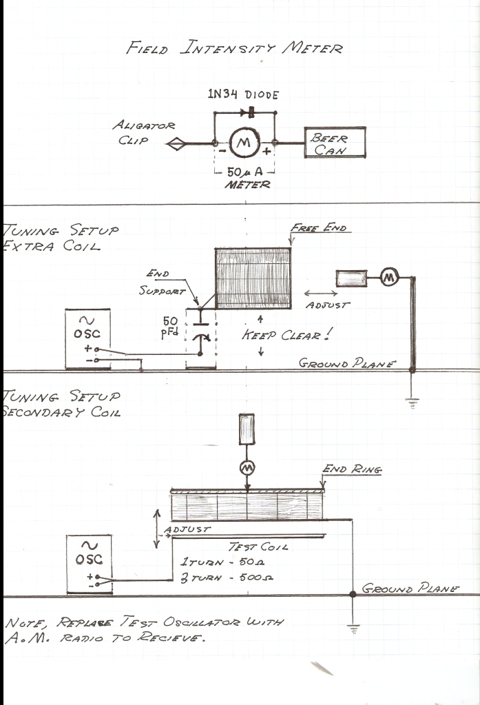
                        Turns out that all you need is an otherwise standard field intensity meter, but with a capacitive probe instead of an inductive probe.

                        Eric Dollard uses a simple beercan as probe:


                        That should work up to 100 MHz or so, I would guess, depending on the quality of your germanium diodes.

                        I am pretty sure that the dipole I used as probe in my attempt to make a longitudinal waveguide antenna actually did resonate in a longitudinal mode:

                        http://www.energeticforum.com/renewa...tml#post176029


                        An important feature of a dipole resonating in longitudinal mode, is that it does not radiate energy away into space. The energy keeps on circulating around the dipole and thus you cannot use an SWR meter, because that one measures the amount of power radiated by the antenna compared to the amount of power fed to it by the transmitter.

                        And that is why my naked dipole appeared not to resonate (no power radiation) and why also nothing happened when I held the dipole in the open wave guide. Only when I inserted it into a waveguide with a bottom, which gives us a capacitive pickup, you would see power being radiated. And that happened because the capacitive bottom would pick up the energy, with which we could get the pipe itself into resonance and thus create a nice normal radiating antenna.


                        To make a long story short:

                        you need a capacitive probe if you want to measure anything longitudinal.

                        Comment


                        • Originally posted by lamare View Post
                          I read there:


                          IMHO, whatever you do on the theory side, you have to ditch two theories:
                          1. Einstein relativity theory;
                          2. Quantum mechanics.

                          Einstein's theory is based on an error in the Maxwell equations. You can read all about that in my article:
                          Tuks DrippingPedia : Ruins 96 Years Einstein Relativity


                          Quantum mechanics is also flawed. I just discovered that this week in a discussion (in Dutch) with a professor, etc.:
                          Skepsis en Niburu op Windesheim over watergas

                          I discussed the well known double slit experiment:
                          Double-slit experiment - Wikipedia, the free encyclopedia

                          The infalling light is explained by Quantum Mechanics as consisting out of "photons" that are randomly emitted by electrons, that change orbit at *random* moments.

                          But, at the other side of the slits, we get a nice interference pattern. In other words: at the exit of the slits, we have two signals that are constantly in phase!

                          How on Earth can that be, if the incoming signals are not also in phase???

                          Answer: it can't.

                          And therefore, the incoming light *must* be in phase and thus cannot be the result of a random process and therefore QM is flawed.

                          That really happens with this experiment, IMHO, is that the light that is being emitted from an ordinary light source is IN PHASE, but of electromagnetic nature. It contains a magnetic, ROTATING component in the aether, which is what causes the observed quantization. And because of this rotational component and this quantization you do not get interference.

                          What happens at the slits, is that this rotational component is removed and after the slits we end up with a longitudinal light wave, WITHOUT magnetic component. And that is the one that DOES interfere.

                          During the discussion, one guy said that this theory was B.S. because interference can also be done with lasers, when they are tightly kept IN PHASE, which was my whole argument to begin with.

                          However, it turns out that lasers actually operate in LONGITUDINAL mode:

                          Laser - Wikipedia, the free encyclopedia


                          Longitudinal mode - Wikipedia, the free encyclopedia


                          In other words, the ONLY theory that has thus far not been falsified is the good old aether theory....
                          Dear lamare!

                          1) A material that you have carefully examined - it's my translation to Russian language multiple messages with the american site AOL Lifestream : Login , which informed the public about the american educational project "Βackyard".
                          This site has worked extensively in the nineties - twothousands years, at a time when the North and South poles of the planet Earth is moved, and quite significantly.
                          After the relative calming of magnetic poles of the Earth financing the american educational project "Backyard" ceased and the site of the project was closed.
                          So don't reprimand ...

                          However, the Proton magnetometers, built on these schemes really work!

                          2) About quantum mechanics.

                          The theoretical basis of Edwin Gray converter is a Quantum mechanics of Feynman, that is largely inconsistent with the theory of relativity.

                          At least, the operating frequency of the converter of Edwin Gray is equal to the operating frequency of the hydrogen MASER, which Feynman determined with a precision of up to 13 significant figures.

                          Description of all transition processes which take place in the converter gray (a priori, which is an open system) is a task much more difficult.

                          Its today successfully solve such theorists as Woodpeckers, rykov and many other supporters of essential theories.

                          If you are interested in the theoretical part of the work - visit our blog at:

                          ðÅÒÅ×ÏÄÞÉË Google

                          There you'll find my basic premises with links to many literary sources that refute the theory Einstein, etc….

                          2) Dear lamare! I do not wish to develop deep theoretical discussions on the site dedicated to the restoration and operation of the invention of Edwin Gray.

                          Today we know, (with high accurately), ALL resonance frequencies - low, high and super-high, on which are flow a different processes in the converter of Edwin Gray, we are aware of all their relationships.

                          That was sufficient for implementation the invention of Edwin Gray, what we do together with Valery Ivanov (Val_001), Russia, with the great success.

                          We wish you no less success!

                          Yours faithfully
                          Leonid Volkov
                          Zaporozhye,
                          Ukraine
                          Last edited by lvleon; 07-27-2013, 04:32 AM.

                          Comment


                          • Originally posted by lamare View Post
                            Creating longitudinal waves on an oscillating dipole is the easiest thing in the world, IMHO. Just take a standard dipole and operate it at pi/2 times it's natural resonance frequency with a standard radio transmitter.

                            The problems is most of all how to measure and detect longitudinal waves.

                            Turns out that all you need is an otherwise standard field intensity meter, but with a capacitive probe instead of an inductive probe.

                            Eric Dollard uses a simple beercan as probe:


                            That should work up to 100 MHz or so, I would guess, depending on the quality of your germanium diodes.

                            I am pretty sure that the dipole I used as probe in my attempt to make a longitudinal waveguide antenna actually did resonate in a longitudinal mode:

                            http://www.energeticforum.com/renewa...tml#post176029


                            An important feature of a dipole resonating in longitudinal mode, is that it does not radiate energy away into space. The energy keeps on circulating around the dipole and thus you cannot use an SWR meter, because that one measures the amount of power radiated by the antenna compared to the amount of power fed to it by the transmitter.

                            And that is why my naked dipole appeared not to resonate (no power radiation) and why also nothing happened when I held the dipole in the open wave guide. Only when I inserted it into a waveguide with a bottom, which gives us a capacitive pickup, you would see power being radiated. And that happened because the capacitive bottom would pick up the energy, with which we could get the pipe itself into resonance and thus create a nice normal radiating antenna.


                            To make a long story short:

                            you need a capacitive probe if you want to measure anything longitudinal.
                            Dear lamare!

                            The converter Gray L-wave really is the place to be, but it is a very short time - at the time of the passage of the sparks. After all, PROPERLY operating Gray's converter DON'T SHOULD ANYTHING TO RADIATE!!!

                            All the energy spin transitions, excited a strong pulse current of electrons, flying through central electrode, should be converted into a static COLD charge electrons with the inverse spin, i.e. the positrons, accumulated in the reservoir.

                            The Gray's converter is a inertia device, therefore, for enhance the utilization of the current pulse we need slow down longitudinal wave with a special slowing structures ...

                            But talking about it here early!

                            At least, better to made a simple experiments, and find the resonant frequencies of excitation the converter of Edwin Gray, which was find Mr. Hakenberger by experimentally, be sure that by these frequencies CPA of the Gray's converter increases by 35 or more dB ...

                            Yours faithfully
                            Leonid Volkov
                            Last edited by lvleon; 06-07-2012, 01:07 PM.

                            Comment


                            • Originally posted by lvleon View Post
                              Dear lamare!

                              1) A material that you have carefully examined - it's my translation to Russian language multiple messages with the american site AOL Lifestream : Login , which informed the public about the american educational project "Βackyard".
                              This site has worked extensively in the nineties - twothousands years, at a time when the North and South poles of the planet Earth is moved, and quite significantly.
                              After the relative calming of magnetic poles of the Earth financing the american educational project "Backyard" ceased and the site of the project was closed.
                              So don't reprimand ...

                              However, the Proton magnetometers, built on these schemes really work!
                              You can still access (parts of) it via the internet archive:

                              Proton Magnetometer:html

                              It seems it is also here: Magnétomètre à protons (schémas)


                              I can't say much about magnetics and resonances with the earth magnetic field.

                              It may very well be that you can perform interesting tricks with the magnetic field of the Earth.

                              I don't know.


                              2) About quantum mechanics.

                              The theoretical basis of Edwin Gray converter is a Quantum mechanics of Feynman, that is largely NO inconsistent with the theory of relativity.

                              At least, the operating frequency of the converter of Edwin Gray is equal to the operating frequency of the hydrogen MASER, which Feynman determined with a precision of up to 13 significant figures.

                              Description of all transition processes which take place in the converter gray (a priori, which is an open system) is a task much more difficult.

                              Its today successfully solve such theorists as Woodpeckers, rykov and many other supporters of essential theories.
                              The point is:

                              Quantum mechanics says that the atoms are NOT resonating in harmony.

                              QM says that in the operation of lasers, masers, etc. EACH atom emits a "photon" RANDOMLY.

                              THAT is not correct.

                              The atoms work together in harmony..

                              The deeper theory about electron orbits, etc. is probably OK.


                              If you are interested in the theoretical part of the work - visit our blog at:

                              ðÅÒÅ×ÏÄÞÉË Google ,

                              There you'll find my basic premises with links to many literary sources that refute the theory Einstein, etc….

                              2) Dear lamare! I do not wish to develop deep theoretical discussions on the site dedicated to the restoration and operation of the invention of Edwin Gray.

                              Today we know, (with high accurately), ALL resonance frequencies - low, high and super-high, on which are flow a different processes in the converter of Edwin Gray, we are aware of all their relationships.

                              That was sufficient for implementation the invention of Edwin Gray, what we do together with Valery Ivanov (Val_001), Russia, with the great success.

                              I am personally concentrating on researching longitudinal waves. It seems to me these may be an important aspect of the Gray device, so I shared some info on that and also what Eric Dollard said on the Gray tube. It may be helpful to you, it may not. If it does use longitudinal waves, then at least now you know how to measure them.

                              For discussing Einstein theory, there is a separate thread:
                              http://www.energeticforum.com/renewa...ain-wrong.html

                              I may start another one for Quantum Mechanics, but I did not have the time to really work all that out in a nice post. I just sketched the essentials, since it may be important in your work to realize that the atoms must be oscillating in harmony, just like electrons in a radio antenna.

                              Comment


                              • Originally posted by lamare View Post
                                You can still access (parts of) it via the internet archive:

                                Proton Magnetometer:html

                                It seems it is also here: Magnétomètre à protons (schémas)

                                I can't say much about magnetics and resonances with the earth magnetic field.

                                It may very well be that you can perform interesting tricks with the magnetic field of the Earth.

                                I don't know.
                                Dear lamar!
                                1) I have the handbook "The Proton Magnetometer" which is placed in the Web archive, I have there are many other books and articles on this topic.
                                I'm introduced here the easiest option the Proton magnetometer, which you gave the second reference, (this is the abridged copy of the message with the original site, which had been closed in 2007). This is the option I have translated into Russian language added to it the image of the others sources, the comments, etc.
                                2) The theoretical basis of proton resonance is written very popular in course of lectures of Dr. Joseph P. Hornak "The Basics of MRI" (English, Italian, Russian).
                                The Basics of MRI

                                If you really are interested in Quantum magnetic measurements - we have a very good book three Russian authors "Physical basis of quantum magnetometry" (RUS)
                                ðÅÒÅ×ÏÄÞÉË Google

                                Try to translate it into English. - it's worth it!

                                Best wishes
                                Leonid Volkov
                                Last edited by lvleon; 07-27-2013, 04:21 AM.

                                Comment

                                Working...
                                X