Announcement

Collapse
No announcement yet.

Gray Tube Replication

Collapse
X
 
  • Filter
  • Time
  • Show
Clear All
new posts

  • quick & dirty method of Eric Dollard's experiment replication

    Originally posted by Spokane1 View Post
    I have just about all of the parts needed for a first run. Mr. Dollard says he used Teflon coated coax, which is available for $2 a foot and I need 100'. I have Teflon-silver #16 AWG stranded and I'm going to use this first. I need to build the Antenna/Transformer structure as well as the loading coil.
    Good luck with the replication Mr. McKay, and don't forget the "white bluish" light bulb which Eric Dollard use to charge the copper sheet. By the way, I have found similar effect by using quick & dirty method with using only high frequency neon sign power supply and strobe lamp. We can compare the results after your experiment is done.

    Wicaksono

    Comment


    • Originally posted by geotron View Post
      Spokane1,

      The ability of a tripole (++-) tube to generate extra electricity through the process of expanding the volume of energy present in an electrolytic capacitor bank through a coil by enabling it to cross the air gap with potential gained from a bank of silicon rectifiers when its poles are connected with a stream of Hi-Voltage and combined together with it is how the system was thought to work!

      A secondary coil would then be used to transform the voltage into a useable level and fed to the source battery in pulses, precicely as done with the other motor circuits. Could it be a matter of using threaded electrodes to obtain a miniscule spark gap for allowing the anode of a 12V battery to be used as input versus having the inverter and all that goes with it providing a resevoir of greater voltage to more readily allow the photoelectric discharge to take place?

      The amount of wattage going through the air gap when the Hi-Voltage pulse is combined with the capacitive medium, a reactive pool normally connected directly to a motor coil instead of colliding through this other potential over the gap is what is said to increase in the process through activating an energetic reaction to take place which has the direct outcome of increasing the resultant magnetic field.


      --

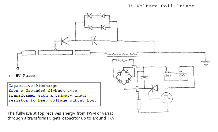
      Something like this?
      http://www.energeticforum.com/renewa...tml#post198728

      Post 22 I posted a schematic for an interesting event that happened to me once.
      Last edited by jake; 07-08-2012, 01:38 AM.

      Comment


      • I've heard tell before of such events taking place; thanks for sharing, interesting circuit.

        This following method should not cause any permanent change to the battery when it is
        pulsed at a low enough recovery voltage. Its ability to produce extra energy is of course theoretical at this point.

        Last edited by geotron; 07-09-2012, 12:32 PM.

        Comment


        • What comes Back Out?

          Originally posted by lamare View Post
          In other words: you can super-polarize a dielectric layer within both an electrolytic capacitor as well as a lead-acid battery, which would result as the cap/battery being observed as having been charged.
          Dear lamare,

          I watched the MIT demonstration and read most of Eric Dollards commentary (at least that which I could understand).

          I have no problems with models that propose that ather is the medium that causes the movement of classical electrons. Nor do I take any issue with the demonstrated concept that the dielectric is the active medium in the storage of some quantum of this ather in plate capacitor structures.

          I also agree that a sharp time rise and slower decay wave form might be able to super charge a cpacitor and/or lead-acid battery under the right circumstances. However this needs to be researched in full measure since a lot of parameters seem to impact this kind of process.

          However, what ever was done to charge the capacitor, be it an exotic wave form or a Whimhurst Machine, it still appears that what comes back out of the capacitor (even if it is OU) is still the same ather that causes classical electron flow that we preceive and measure as magnetic fields and current.

          This is not the historical case with the E.V. Gray technology. Whatever came back out of his storage capacitors created magnetic fields two to three orders of magnitude greater than what could be stored in the capacitor with classical electrostatic charge alone (or aether). It is highly unlikely that this output was just a huge increase in this same classical charge (or aether). If that much classical energy were applied directly to the engine coils they most likely woud have exploded like an exploding wire experiment. So there was something vastly different about the energy that was harvested and how it interacted with inductive loads.

          This suggests that what ever went into the capacitor was different to start with. But I will not over look models that suggest some kind of conversion process similiar to the super-charging idea that can take place in the capacitor. The main requirement is that the final output product displays these novel porperties.

          Speculation: The dielectric properties that you provided for this discussion are still very important and in the end will be the very foundations of this technology. I maintain that the novel "something" is created by the strong magnetic and electrostatic excitation of a dielectric - specifically an electrret type material. If Eric Dollard's experiment proves meaningful then the active material in his setup will be shown to be the Teflon on his secondary coax cable.

          I propose that Marvin Cole was using the large "Floating Flux Field" conductors. Who knows what he was using for a dielectric. It could have been Teflon or polyethylene if he was employing commercial "Hard Line" coax. For the short length of cable involved in th EMA4 engine (about 6') he could have cast just about anything into a custom component that looked like a cable.

          In 1974 it appears that Richard Hackenberger upgraded the FFF from single turns of a large conductor (between 0.500" and 0.750" in diameter) to 2 or 3 turns of a smaller cable (0.250" to 0.375" in diameter). It is unlikely that he took the time to custom cast these longer custom cables with designer dielectrics. So there is more historical evidence for commercial cables being used all along.

          If they were coax cables then they might have been "conditioned" to become electrets. This done by heating the cable in an oven and applying a large voltage potential across it. (like 15 kV DC) Then allowing this configuration to cool over a 3-4 day period. I have read where this works for polyelethyene coax. I have no idea what this would do with Teflon.

          After the "charging" process the shield and outer insulation could have been removed to expose the bare activated dielectric or lnear electret. It appears that if this did happen then a new outer insulation jacket was re-applied, perhaps heat shrink material. Who knows if it was this complicated. This dialog only shows what could have been done.

          Any thoughts?

          Mark McKay

          Comment


          • Perhaps an NST?

            Originally posted by Wicaksono View Post
            Good luck with the replication Mr. McKay, and don't forget the "white bluish" light bulb which Eric Dollard use to charge the copper sheet. By the way, I have found similar effect by using quick & dirty method with using only high frequency neon sign power supply and strobe lamp. We can compare the results after your experiment is done.

            Wicaksono
            Dear Wicaksono,

            I certainly hope that the use of the Diathermy Machine can be replaced with some comercial transformers in these kinds of circuits. It would be a real dissapointment for non-funded researchers if the only thing that worked was a device made in 1920 and is in limited supply.

            NST's will probably be able to demonstrate some kinds of weak effects, but I think their overall use will be limited. Thier internal magnetic shunt design used for current limitation is a real drag on effective energy conversion. Just when you need the voltage their current output drops like a stone.

            If the power supply for the Blue Engine is what I think it is then we will all be winding our own custom ferrite core HV transformers that operate between 6 and 15 kHz. at 3 kv to 5 kV rectified square wave pulses. This appears to be what his conversion components needed to do their Thing. This construction may not be as bad as it seems since he used an "E" form which lends itself to home-brew work.

            Well time will tell.

            Mark McKay

            Comment


            • The Shocking Experiance

              Originally posted by jake View Post
              Something like this?
              http://www.energeticforum.com/renewa...tml#post198728

              Post 22 I posted a schematic for an interesting event that happened to me once.
              Dear Jake,

              Your experiance is not all the uncommon. I have heard other reports about people who get zapped like this and then it never happens again with the same circuit.

              I would suspect that you have hit upon a fundamental property of this proposed process. The dielectric (perhaps the wire insulation) will generate one pulse of this anomalous "something" then become saturated in the one polarity and not do it again for a long time if ever.

              The design of the E.V. Gray converter suggests that some kind of "push-pull" action is required. The wiring of the "Floating Flux Field" is such that when the positive pulses are applied they enter the "FFF" coil at the opposite ends. IF the square wave pulses are applied out of phase then the electric field between the coil conductors will alternate and thus stress the dielectric 180 degrees every other cycle. Such action may just reset the structure of the material to be able to generate another shot of this wonderful "something".

              Apparently you can do this pretty quickly if the applied pulses are between 6 kHz and 15 khz.

              Thanks for sharing your experiance. In this business these little clues can add up.

              Mark McKay

              Comment


              • Flyback Charging Circuit

                Dear geotron,

                What comes out of your capacitor after it is charged to 1 kV?

                I know this is a tough question if you are not set up to measure it. But this question is central to this technology.

                I'm using opposing coils salvaged from some commercial school clocks. The motor coils are 5/8 thick by 1-1/2" in diameter. They run about 900 Ohms DC so there is a lot of fine wire wound on that little bobbin. Never the less the price was right.

                I have these two coils wired in parallel with a 1/2" x 18" plastic rod going through the center of them. I have a 5 uf 5kV capacitor that I change with either the output of my latest conveter circuit -OR- the output of my Fluke #508 500 watt 5kV regulated power supply (tube). A 120 VAC contactor connects the capacitor to the opposing coils. I then compare the jumping height of the opposing coils with the converter output then again with the classical output of the power supply. So far I have not noticed any differance with any of the circuits that I have tested in the past.

                I'm looking for a difference in acheived height of at least 10%. By rights if a converter circuit were to generate 100% of this anomalous "something" then the little poiing coil should fly right off the support rod and put a noticable dent in the ceiling. So far this hasn't happened.

                We are pretty sure that the anomalous "something" could be measured with an Analog Meter, specifically a Tripplett Model #630 using the 5 kV tap. This was a several meg ohm resistor tied directly to the 50 microamp meter movement. Who knows if that setup was reading the "something" or just classical electron contamination. Most likely it was a mixture of both.

                You may really be on to something if what is collected in your storage capacitor displays some non-classical behaviour.

                My popping coil approach is probably not the only method to check for the anomalous "something". If you come up with another idea, I'm sure we all would like to hear about it.

                Mark Mckay

                Comment


                • Originally posted by Spokane1 View Post
                  Any thoughts?

                  Mark McKay
                  Dear Mark,

                  I think the most fundamental issue to understanding all these kinds of OU systems is to be found in the understanding of the role the aether itself plays within all these phenomena.

                  First of all, in essence electrons and atom nuclei ARE some kind of localized EM wave themselves, because of the wave particle duality principle. So, *all* physical phenomena we know ARE interactions of E(M) wave phenomena one way or the other. So, at some point, the idea that even normal currents are in essence the movements of charge carriers, electrons, is no longer valid.

                  Let's first take a brief look at quantum mechanics. The basis of that lies in the explanation of the famous double slit experiment, which shows the wave particle duality principle. That is perhaps the most fundamental principle of physics. Particles ARE some kind of E(M) wave phenomenon.

                  However, where things went wrong is when the idea was formulated that a single electron changing it's orbit around an atom nucleus is capable of emitting a photon, an EM wavelet, with a wavelength thousands of times longer than the radius of an atom. From that idea, you get the situation that light emitted from a light source, such as an ionized gas, would be a bunch of photons, each with a random phase because the electrons are supposed to fall back in orbit at *random* moments. That cannot be, because then you would get a (large) number of EM wavelets at your double slits with *random* phase thus canceling out. Therefore, the concept of electrons changing orbits randomly has to go. It is untenable.

                  Further experiments with this double split principle, show that you can have "single" photons or even electrons that produce an interference pattern, whereby a single photon or electron appears at one of the maxima in your interference pattern, which leads to the crazy concepts that particles supposedly can exist at multiple places at the same time, etc. All those ideas have to go.

                  What really happens, IMHO, is that you simply have three separate wave propagation modes that give rise to these phenomena, whereby the longitudinal mode has been overlooked:

                  1. longitudinal mode;
                  2. classic transverse EM mode, at the boundary of two media with different "density";
                  3. vortexes - an EM mode running around in circles.

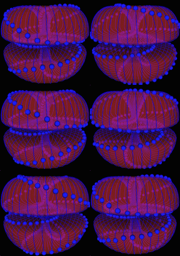
                  It is these vortex structures we call particles, which may look something like this:


                  What is very important to understand is that these vortex based localized EM wave phenomena cannot interfere as the other wave modes can, because there is a resulting rotational force, the "magnetic" moment, which drives the "particles" away from one another, unless you bump them on to one another with large velocities, such as they like to play with in CERN.

                  In other words: as long as the wave phenomena we are talking about are in their vortex-based propagation mode, you cannot get interference.

                  That means that the double split experiment *must* be a longitudinal phenomenon and therefore what happens at the tiny slits is that the propagation mode changes from "particle mode" to "longitudinal mode".

                  And now to the point: Because one is able to detect single photons or electrons in the double split experiment, which IS a longitudinal interference phenomenon, it is clear that electrons and photons *can* be "created" by longitudinal waves.

                  In other words: under the right circumstances, the propagation mode can change from longitudinal to "vortex based", whereby it appears that an electron or photon interferes with itself and can be at multiple "places" at the same time and then an "observation" influences where it actually "locks" into reality or something. In reality, it is simply a matter of a number of changes in propagation mode of a wave phenomena, whereby one mode is "invisible", because we don't even bother trying to measure them because we think they can't exist because of a fundamental error was made in the Maxwell equations. (see my Einstein article).

                  To sum this up: particles can flip in propagation mode from "particle" to "longitudinal", whereby in "particle / vortex" mode you have the particle characteristics, while in longitudinal mode you have the wave characteristics giving rise to the wave particle duality principle.

                  This principle is needed in order to explain not only "quantum" electron tunneling effects, but also in order to really explain the MIT experiment.

                  Now that we have ditched the idea that electrons randomly change their orbits in order to emit photons, it is clear that the mechanism whereby light is emitted from a light source must be a resonance phenomenon, whereby indeed the electrons do change orbit, BUT they do so in a deterministic manner. All these tiny "resonators" are locked in phase and that way you sort of get an antenna array, so you do not get a single electron orbit transition emitting a single photon, but an array of lots of electron orbit transitions locked in phase emitting a continues stream of EM energy, just like with a normal RF antenna. The only difference is that with normal RF radiation the movements of the electrons are different. With normal RF radiation, you get electrons jumping from one atom nucleus to the next, while with light emission you get electrons changing orbit around a single nucleus. BUT the movements are locked in phase and deterministic. It is lots of small movements adding up because of RESONANCE.

                  In other words: what we are looking at, are longitudinal resonance phenoma taking place within some material, either emitting RF waves or light waves, whereby at some distance of the material you get a mode transition from "longitudinal" within the material, to a classic transverse mode at the surface (border) of the material, which on its turn transits into "particle" mode emission of "photons". The latter mode transition is what we know as "near field" vs. "far field" in RF engineering:

                  Originally posted by lamare View Post

                  So, in essence, Tesla did not realise that there was such a thing as a near field and a far field. And actually, modern science literally makes "things" known as "virtual photons" up in order to hide the fact that they don't have the slightest idea what they are really talking about:

                  In the quantum view of electromagnetic interactions, far field effects are manifestations of real photons, while near field effects are due to a mixture of real and virtual photons. Virtual photons composing near-field fluctuations and signals, have effects which are far shorter range than do real photons.
                  Yes, that's what it says. Near field effects are due to a mixture of something real and something completely made up aka "virtual", which is literally another word for "imaginary" or "not real".

                  Update: Prof. Meyl shows this very nicely in his "Wireless Tesla Transponder":
                  http://www.tuks.nl/pdf/Reference_Mat...ransponder.pdf

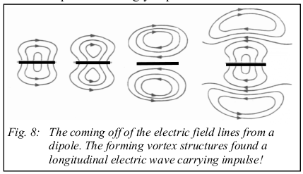
                  In the text books one finds the detachment of a wave from the dipole accordingly explained. If we regard the structure of the outgoing fields, then we see field vortices, which run around one point, which we can call vortex center. We continue to recognize in the picture, how the generated field structures establish a shock wave, as one vortex knocks against the next [see Tesla: 1].
                  Thus a Hertzian dipole doesn’t emit Hertzian waves! An antenna as near-field without exception emits vortices, which only at the transition to the far-field unwind to electromagnetic waves.
                  However, the accompaning explanation sucks, because IMHO the far-field actually consists of vortices, "particles" with that mysterious wave-particle duality, so he may have to re-do some of his homework.
                  All right.

                  Now it is clear that light emission (in the infrared spectrum) is a process that occurs readily in all kinds of materials, which is measured as heat or temperature. Now of course, there is no reason why you could not have "electron" emission along the same principles. After all, it's in essence a matter of a transition of a longitudinal wave phenomenon inside a material into a different propagation mode, whereby vortexes appear.

                  In other words: the whole concept of charge being tied to electrons and that you have to count the electrons in order to determine the "charge" on a capacitor is a simplification that is no longer valid in the study of the phenomena we are researching. To put it in the words of Steinmetz once again:

                  "Unfortunately, to a large extent in dealing with the dielectric fields the prehistoric conception of the electrostatic charge on the conductor still exists, and by its use destroys the analogy between the two components of the electric field, the magnetic and the dielectric, and makes the consideration ot dielectric fields unnecessarily complicated. There obviously is no more sense in thinking of the capacity current as current which charges the conductor with a quantity of electricity, than there is of speaking of the inductance voltage as charging the conductor with a quantity of magnetism. But while the latter conception, together with the notion of a quantity of magnetism, etc., has vanished since Faraday's representation of the magnetic field by the lines of magnetic force, the terminology of electrostatics of many textbooks still speaks of electrostatic charges on the conductor, and the energy stored by them, without considering that the dielectric energy is not on the surface of the conductor, but in the space outside of the conductor, just as the magnetic energy."
                  Break. More to follow.

                  Comment


                  • Originally posted by Spokane1 View Post
                    However, what ever was done to charge the capacitor, be it an exotic wave form or a Whimhurst Machine, it still appears that what comes back out of the capacitor (even if it is OU) is still the same ather that causes classical electron flow that we preceive and measure as magnetic fields and current.

                    This is not the historical case with the E.V. Gray technology. Whatever came back out of his storage capacitors created magnetic fields two to three orders of magnitude greater than what could be stored in the capacitor with classical electrostatic charge alone (or aether). It is highly unlikely that this output was just a huge increase in this same classical charge (or aether). If that much classical energy were applied directly to the engine coils they most likely woud have exploded like an exploding wire experiment. So there was something vastly different about the energy that was harvested and how it interacted with inductive loads.

                    All right. What we are apparently looking at with a "polarized" dielectric, is a spacial structure, wherein a number of super-imposed longitudinal resonance phenomena take place. One of the things this emits is light in the infrared or higher wavelength range, depending on the temperature of the material. In semiconductors, such as an LED, one can disrupt the balance within the spacial structure, so it emits light in the visible range once applying an electric field.

                    Given the MIT experiment, a polarized dielectric is apparently capable of emitting and absorbing "light" in the range of the wavelength we associate with electrons.

                    In other words: there is no actual "storage" of electrons. What there is, is the emission and absorption of E(M) waves, which transit from one propagation mode into another at the boundary between the dielectric and the metal. So, you actually get "creation" of electrons at one boundary and "destruction" / absorption at the other boundary, which are nothing more and nothing less then a transition of the propagation mode of an E(M) wave from "vortex/particle mode" into "transverse mode" into "longitudinal mode".

                    Within the material, you have a longitudinal resonance mode, at the boundary you have the classic transverse mode and further away from the surface (of a conductor), you get the transition of transverse mode into vortex/particle mode. In other words: the heating of a filament in an amplifier tube does not "rip" electrons out of the material. It comes in such a resonance mode that it actually "creates" electrons and emits them into free space.

                    Interesting effects occur when a sudden change in the configuration of an electric circuit occurs, such as the firing of a spark gap. These are what Steinmetz called "transient phenomena":

                    "Theory and calculation of transient electric phenomena and oscillations"
                    Theory and calculation of transient electric phenomena and oscillations : Steinmetz, Charles Proteus, 1865-1923 : Free Download & Streaming : Internet Archive

                    The characteristic of all these phenomena is that they are transient functions of the independent variable, time or distance, that is, decrease with increasing value of the independent variable, gradually or in an oscillatory manner, to zero at infinity, while the functions representing the steady flow of electric energy are constants or periodic functions.

                    While thus the phenomena of alternating currents are represented by the periodic function, the sine wave and its higher harmonics or overtones, most of the transient phenomena lead to a function which is the product of exponential and trigonometric terms, and may be called an oscillating function, and its overtones or higher harmonics.

                    A second variable, distance, also enters into many of these phenomena; and while the theory of alternating-current apparatus and phenomena usually has to deal only with functions of one independent variable, time, which variable is eliminated by the introduction , of the complex quantity, in this volume we have frequently to deal with functions of time and of distance. We thus have to consider alternating functions and transient functions of time and of distance.
                    It is these transient phenomena, whereby you get the propagation of some disturbance in the aether (the electric field) which propagates with a speed of pi/2 times c for a very short time, until it has propagated along your circuit and thus the balance between the internally resonating materials returns.

                    And it is this phenomena, this transient, this shockwave, which is an energy form that essentially gives rise to the classic (relatively) low-frequency phenomena we call currents, but which of itself is NOT a carried by particles (which are E(M) waves) BUT by the aether itself.

                    And it is that energy form that Tesla referred to as the wheelwork of nature...

                    In other words: there is a lot to be researched, but also quite a lot of knowledge is already there in the work of a/o Steinmetz.

                    And one thing is clear: the interesting phenomena we are after stick their head out of the mud with fast-switching "transients", which give an opportunity to use an energy flow that is NOT transported by particles but by the aether itself....

                    And what Gray essentially did, was to harnass this transient phenomena by turning it into a usable magnetic field. And we do have the formula by which that can be done:

                    Maxwell's equations - Wikipedia, the free encyclopedia

                    Ampère's law with Maxwell's correction states that magnetic fields can be generated in two ways: by electrical current (this was the original "Ampère's law") and by changing electric fields (this was "Maxwell's correction").
                    In other words: changing electric fields, "transients", CAN give rise to magnetic fields. And since we are talking about a) a huge change in voltage AND b) a propagation speed greater than c, we get an extreme dE/dt and thus the potential to create an extremely strong magnetic field.

                    The question is: how do you guide this transient such that you get a usable magnetic field?

                    As I stated before, there are quite a few things to take into account:

                    1) the push-pull principle, as demonstrated by Wheatstone, which suggests you need two coils in series.

                    2) the propagation of the transient along your coil.


                    One of the things is that the propagation of the transient along your coil may be improved by the use of a dielectric as a core, so you can guide the transient shockwave along your coil and perhaps create a situation that it rotates multiple times around your coil so that the "transient" maintains the magnetic field it creates for a longer time than in the order of nano-seconds or less.

                    Another idea may be that you can get the transient to come into "Schumann" resonance along the surface of your coil, which may be what we are able to do with, again, the use of a dielectric core.
                    Last edited by lamare; 07-11-2012, 07:57 AM.

                    Comment


                    • Originally posted by Spokane1 View Post

                      In 1974 it appears that Richard Hackenberger upgraded the FFF from single turns of a large conductor (between 0.500" and 0.750" in diameter) to 2 or 3 turns of a smaller cable (0.250" to 0.375" in diameter). It is unlikely that he took the time to custom cast these longer custom cables with designer dielectrics. So there is more historical evidence for commercial cables being used all along.
                      This also points in the direction of getting a transient creating an extreme dE/dt, as is also used by Tesla as the primary of his TMT. Dollard says it needs to be one turn of shield copper IIRC. See a/o page 7:

                      http://www.tuks.nl/pdf/Eric_Dollard_..._Coils_OCR.pdf


                      What happens with the TMT primary is that it is put in resonance, using the negative resistance area of a spark gap in order to amplify the oscillation of/in the primary. And since that is not a nice harmonic, but a spike with a fast rising edge and a relatively slow falling edge, one can apparently get a single turn coil into a resonance mode, whereby actually this transient phenomena is kept alive and not only that, it is kept in resonance for some time.

                      What happens when you use dielectric coated or filled conductor, such as a coax cable, is that the propagation speed of the transient becomes substantially slower. And another effect may be that the transient is being contained in a much smaller volume, preventing inter-turn interference.

                      That way, you may be able to a) use multiple turns without problems and b) work at considerably lower resonance frequency.

                      I have quickly looked a bit up about this FFF, and it is interesting that we see two coils:

                      Evolution of the E.V. Gray Circuit Topology -- by Mark McKay


                      That suggests that this is needed because of the pull-push principle discussed before, especially since the +/- appear to be wired such that they would oppose one another with normal currents.


                      All this points in the direction that you need two coils in series because of the push-pull principle, which are put into "transient" resonance using a spark gap in it's negative resistance mode of operation, such that the waveform propagating along your coils has the characteristics of a spike with a sharp rising edge and a soft dropping edge.

                      Update:

                      Let's look at the schematic:


                      It looks like there is a magnetic coupling (circuit) between the core of the floating flux field coils and the coils being activated on the rotor, whereby there is a closed magnetic loop.

                      Since the FFF coil would be the oscillating coil, which determines the oscillation frequency of the transient, and there is a spark gap in series with both coils, it appears as though the transient oscillation may arise because the self-capacitance of the stator/rotor coils acts as the capacitor needed for the transient oscillation to occur. So you then have the (relatively LF, long) FFF coil in series with a spark gap and the stator/rotor coil(s), which for the transient do not really act as coils, but as (inter turn) capacitors.

                      The magnetic field is created by the FFF coils during the transient, whereby the discharge of caps 25/26 as a normal current trough the spark gaps and the stator/rotor coils occurs in resonance with the transient from the FFF coil, because of the magnetic coupling between all the coils along a closed magnetic loop. And that normal current is probably necessary in order to get and keep the spark gap into it's negative resistance mode of operation...

                      In other words, we may be looking at:

                      1) initial phase: spark gap snaps, voltage difference between the FF and stator/rotot coils, transient oscillation between FFF coil in series with spark gap and self capacitance of stator/rotor coils.

                      2) (pulsed) magnetic field created by FFF induces normal oscillating, pulsed "spiking" current in stator/rotor coils, because of closed magnetic loop, whereby the normal discharge of caps 25/26 trough the spark gap and the rotor coils, which is in phase with the FFF coil, keeps the transient phenomena of the FFF coil alive and in oscillation, until the caps 25/26 are discharged normally trough the rotor coils.

                      And since the spark gap is in series with both the FFF and rotor/stator coils, you get a superposition of the transient oscillation signal of the FFF coil and the normal oscillating from the discharge of the capacitor in the rotor/stator coils.

                      So you keep the transient signal alive using a resonating normal current by the discharge of caps 25/26 trough the same spark gaps trough your rotor/stator coils.


                      To put it another way: the transient oscillation of the FFF coil is amplified by the magnetic coupling between the FFF coil and stator/rotor coils, which is kept alive for some time by the pulsed discharging of caps 25/26 trough the spark gap and stator/rotor coils IN PHASE with the transient oscillation in the FFF coils....

                      Or would that bee too far fetched?

                      Update 2: If we are to believe Magratten (see post below), then the position of spark gaps 29/30 and coils 27/28 should be reversed....


                      In that case, you get a reason for putting a "major" and a "minor" coil in series.... And then, your FFF coils would simply be delay lines, in order to prevent the shockwave from reaching your coils trough the frame ground connection too early...

                      And that is also what the patent says (above article by Mark):
                      There is not much written about the “Floating Flux Field”. The patent 3,890,548 text states:

                      “The rectified unidirectional pulsating output of each of the diodes in converter 38 is passed through coil 23, 24 thus forming a harness 37 wound about the case of the engine, as hereafter described, which is believed to provide a static floating flux field. The outputs from delay lines 37 drive respective capacitors in banks 39 to charge the capacitors there in to a relatively high charge potential”

                      Further on in the patent text we read:

                      “Around the central outer surface of housing 50 are wound a number of turns of wire 23, 24 to provide a static flux coil 114 as herein before described, which is a delay line as previously described.”

                      This is all that was disclosed in patent 3,890,548. It is interesting to note that this novel component was not even listed in the multiple claims detailed at the end of the patent text. Who knows what the term “Static Floating Flux Field” meant, but it is certain, from the operation of this device, the field was anything but “static”.

                      Note that Magratten's step-up transformer is NOT connected to frame ground...

                      So, I guess the above was a bit too far fetched indeed.


                      Update 3: And if indeed one of the oppozing shockwaves energizes the coil in the opposit direction as the normal current, then you have a reason for the major/minor coils being unequal. In that case, one would guess the major/minor coils to have an equal length of coil wire, but a different number of windings. That way, you could create a situation that the shockwaves add up and strengthen one another, while the normal current can only partially oppoze the preciously built up magnetic field.

                      However, that is speculation....
                      Last edited by lamare; 07-11-2012, 08:53 PM.

                      Comment


                      • Originally posted by Spokane1 View Post
                        I have these two coils wired in parallel with a 1/2" x 18" plastic rod going through the center of them.
                        Spokane1,

                        What would happen if you were to have the input to the second coil on a spark gap to the output of the first one? When the energy is passing over the gap it could also pass over the cathode of a hi-voltage diode blocking it from reaching the anode of a motor capacitor. This capacitor could have its cathode at the output side of the second coil.

                        Comment


                        • high frequency NST

                          Originally posted by Spokane1 View Post
                          NST's will probably be able to demonstrate some kinds of weak effects, but I think their overall use will be limited. Thier internal magnetic shunt design used for current limitation is a real drag on effective energy conversion. Just when you need the voltage their current output drops like a stone.
                          Yes, what I mean with HF neon sign power supply is actually a NST, but since it is not only a transformer (it has DC input & switching transistor, just like the one you have) then I prefer to use the word power supply. And I know what you mean about current limited NST will only make weak effects, if it is connected between strobe lamp electrodes. But actually my setup is a little different, the NST is connected between an electrode and the trigger grid. By this way, the current is minuscule because the lamp glass acts as insulator. You can check this for yourself if you have a strobe lamp connected to your NST. By the way, what is the frequency output of your NST ?

                          Wicaksono

                          Comment


                          • Magratten patent

                            Gary Magratten published a patent for a device which is derived from Gray technology:

                            Electron avalanche drive circuit - Magratten, Gary J.
                            http://www.tuks.nl/pdf/Patents/Gray/...0110188278.pdf

                            This may give some further clues...

                            Edwin V. Gray employed a high voltage spark gap exposed to open air in his U.S. Pat. No. 3,890,548 entitled, Pulsed Capacitor Discharge Electric Engine issued Jun. 17, 1975. The purpose of the spark gap was to provide accurate timing for the discharge of capacitors. At the time, those skilled in the art were unaware that electron avalanche, as developed in a high voltage spark gap exposed to open air, could increase the current to the inductive load. Carefull examination of the placement of the spark gap in the patent drawings show the spark gap after the inductive load rather that before it. This prevented additional current from electron avalanche from being employed to the inductive load.

                            At present there is no known electric power drive circuit operated on the principle of electron avalanche as developed in a spark gap exposed to open air in order to increase the current delivered to the load. The employment of electron avalanche as developed in a high voltage spark gap exposed to open air for the delivery of additional current to an inductive load is unobvious to all skilled in the art. The result achieved by the employment of the invention for the delivery of increased current to the inductive load is new, unexpected and superior to all prior art.

                            The prior art referenced were inoperative in that they did not employ electron avalanche in a practical way for the delivery of increased current to the load. The prior art referenced were also inoperative in that they were impossible to succesfully be reconstructed. Another novel mechanism associated with the invention is the use of a high speed, unidirectional switching system to release the additional current developed by electron avalanche from the main circuit.
                            Update:

                            Given Magrattens track record, I would guess that the "preferred embodiment" and fig 3 (power from mains) has indeed been tested and actually worked, while fig 2 (Electron Avalanche Drive Circuit with a resistive heating element load) may very well be an educated guess and/or an intentional red herring. Fig 3:


                            The principle appears to be to have a high voltage cap discharged trough a spark gap to the inductive load, triggered by a commutator (312), while there is a step-down transformer in series with the main (oscillating?) coil (close to the spark gap) which function is to steer a (fast switching) relay in order to dump some normal current to ground. Note that the step-down transformer is at the opposite side from the spark gap to the inductive load.

                            Why no details on the inductive load??
                            Why the dumping of current to ground??

                            We can find some more clues in this 2011 article, apparently a *working* prototype:
                            PEMM Motor Harnesses Anti-matter and Electron-Avalanche


                            The capacitor is pulsed by the commutator. This occurs when the rotor electromagnet is approximately two degrees or one fourth inch past the stator. At this position the electrodes align with a high voltage potential. This allows a spark to jump the gap from the cathode (negative pole) to the anode (positive pole) through atmosphere. It is during this moment that a couple of very unique phenomena take place that allow for the circuit to increase in current and voltage -- hence an increase in total power. This increase in total power (beyond what was provided by the battery) is one feature that makes this motor unique.

                            The motor connected to this circuit is composed of multiple stator and rotor electromagnets. No permanent magnets are used. Currently, the electromagnets use silicon steel laminations as core material. It is hoped in the future that supermalloy, permalloy, or mumetal will be used for the cores. The increased permeability of these materials could allow for even more torque to be produced in this already high torque motor.
                            Note that his patent was filed in feb 2010.

                            Interesting:

                            Silicon Steel for Laminations

                            Silicon Steel (Electrical Steel)

                            When low carbon steel is alloyed with small quantities of silicon, the added volume resistivity helps to reduce eddy current losses in the core. Silicon steels are probably of the most use to designers of motion control products where the additional cost is justified by the increased performance. These steels are available in an array of grades and thicknesses so that the material may be tailored for various applications. The added silicon has a marked impact on the life of stamping tooling, and the surface insulation selected also affects die life. Silicon steels are generally specified and selected on the basis of allowable core loss in watts/lb.
                            Another interesting detail from pes article:

                            Immediately after the spark crosses the gap between electrodes, the stator and rotor electromagnets fire and produce a repulsive force. However, when the pulses cease, the magnetic field rapidly starts to collapse and reverse polarity. This is due to the concept of "Back EMF." Due to the fact both stator and electromagnets are both experiencing this effect at the same time (in phase with each other) an additional repulsive force is created. For example, if the pulse initially created a condition in which both stator and rotor electromagnet had a "north" pole facing each other after the field collapse they would both have a "south" facing pole. This effect produces additional torque the system can utilize.
                            A rather curious understanding of Back EMF. Yes, there is a change of polarity of the *voltage* but NOT of the magnetic field. Back EMF is the *collapsing* of the magnetic field, not a reversal of magnetic polarization!

                            All right. Now some educated guesses.

                            First of all, the length of the coil wire in the primary (HV side) of the step down transformer 318 is probably considerably longer than the length of the coil wire in the "inductive load".

                            At the moment the spark gap fires, both coils 316 and 318 are at high potential.

                            Now when the spark gap fires, you get a transient shockwave exiting both sides of the spark gap simultaneously, in the OPPOSITE direction, which propagate along the circuit, guided by the conductors, Steinmetz' transient phenomenon. In the case when you do not use a step down transformer, but you have two identical coils in series, these shockwaves are apparently capable of energizing the coils in opposite directions, because the delay along the wires and HV cap can be neglected. And if the coils are identical, the oppozing shockwaves meet nicely in the middle canceling one another out and thus restoring the balance of the aether. This process happens within the order of nanoseconds, after which the normal discharge occurs, strengthening the already energized coils.

                            In the case you have a single coil as inductive load, the oppozing shockwave reaches the terminal on the opposite side of the spark gap almost instantly and then the party is over. However, when you put a step down transformer with a long primary in the line, then the primary of the step down transformer acts as a delay line, so then the shockwave can energize your inductive load before the opposite shockwave reaches the other terminal of your inductive load, which it probably never does, because if the primary is indeed long enough, the shockwaves will meet somewhere within the primary of the step down transformer.

                            Once the coil is energized by means of both the shockwave AND the normal discharge, you get the back EMF. And that is the one that is dumped to ground using the fast switching relay, which can be a semiconductor according to the patent.
                            Last edited by lamare; 07-11-2012, 08:43 PM.

                            Comment


                            • Gary Magratten's Work

                              Dear lamare,

                              That certainly is a nice write up on Gary's past work. I suppose it took you several hours to compose all that technical writing.

                              I was wondering if your commentary included Gary's most recent work? Just before the conference Gary sent me a large envelope and some large 8"x10" color photos of his latest exploration. Did you happen to get a copy of that report?

                              Mark McKay

                              Comment


                              • Originally posted by Spokane1 View Post
                                Dear lamare,

                                That certainly is a nice write up on Gary's past work. I suppose it took you several hours to compose all that technical writing.

                                I was wondering if your commentary included Gary's most recent work? Just before the conference Gary sent me a large envelope and some large 8"x10" color photos of his latest exploration. Did you happen to get a copy of that report?

                                Mark McKay
                                Nope, don't have that. Would be nice if it could be published, but even if it cannot be published I would love to have it.

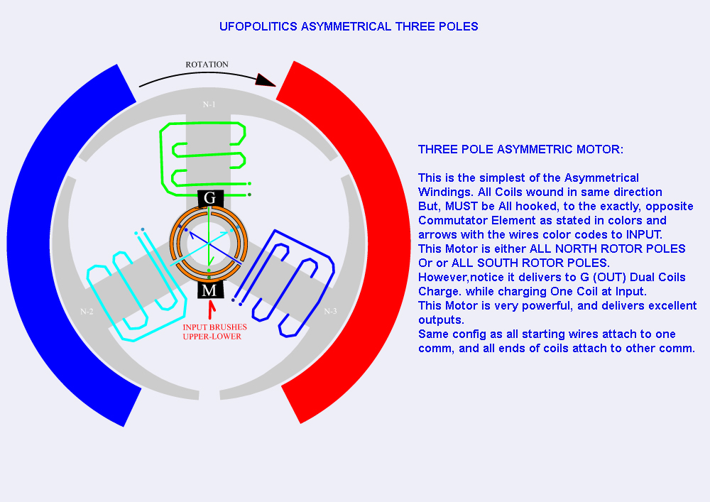
                                However, we may find some more clues in the system currently being disclosed by UfoPolitics on his thread. I commented some over there, and the idea of creating a disbalance in an asymmetric system is intriguing:

                                Originally posted by lamare View Post
                                Originally posted by Ufopolitics View Post
                                Oh!, I have a great present here for you all to have lots of fun with...Well "presents for some...and kind of "Head Aches" for some Classic Symmetrical Physics "Experts"...


                                <snip>

                                So... it should not turn Right Lamar?...However, it DOES!...and AWESOME!!

                                Now, why do you think that Happens Lamar?...If "supposedly" this Coils-Inductors "never" change their polarity??!!...
                                <snip>

                                All right. What you are looking at in this picture is that N2 and N3 are not activated from the battery. Therefore, their polarity is being determined by the permanent magnet. In other words: N2 is S (induced by the N of the PM) and N3 is N (induced by the S of the PM).

                                In the current position of the rotor, in the case there would be no current flowing trough the N1 coil, N1 would be neutral in the centre, while you would have an S at the left (induced by the N of the PM at the left) and a N at the right (induced by the S of the PM at the right). In that case, most of the magnetic fieldlines would go trough N2 and N3, and some trough the top of N1.

                                The firing of N1 makes it a N, which is attracked by the S of the PM, and the closer it gets to the magnet, the stronger the N becomes, because the PM amplifies the pole already induced by the coil, because iron is being attracted by a magnet, by which process the iron gets magnetized by the PM by magnetic induction.

                                That is all the pretty much like with a normal motor.

                                Now I realize that the big difference is that N2 and N3 are also connected to a brush on the commutator, most notably during that part of the cycle where the pole moves in/out of the PM, causing a collapsing or building of a magnetic field in the core within the coil, which normally induces a high voltage in the coil, which gives a spark in normal motors.

                                And THAT is the problem with a normal motor, a problem that has been overlooked by everyone.

                                You see, the problem with a sparking coil is that you get very powerful phenomena taking place, which Steinmetz called "transients" about which he wrote a whole book:
                                Theory and calculation of transient electric phenomena and oscillations : Steinmetz, Charles Proteus, 1865-1923 : Free Download & Streaming : Internet Archive

                                And you only need to look at Edwin Gray's motor, which somehow harnassed these powerful transients by discharging a HV cap trough a spark gap into his coils, to realize that unwanted/uncontrolled sparks are a big headache in motors with coils. They generate much more powerfull (negative) effects than is being realized.

                                Now because your coils are connected to your generator brushes during that part of the cycle where the pole moves out of reach of the PM, you don't get these sparks and thus do not get these very powerfull transients that ruin the party in normally wired motors.

                                If this is correct, then I would say that you will not be able to have the motor power itself just by using the generator windings to re-charge your batteries. BUT you have all the torque on the shaft which you can use almost for free, so if you connect a separate generator to the shaft, you may very well be able to create a self-runner.

                                Originally posted by lamare View Post
                                Yes, that is about the idea. It is very hard to connect al the dots theoretically, but I see a certain analogy with Milkovic' pendulum:

                                Veljko Milkovic - Home Page - Official presentation of the researcher and inventor Veljko Milkovic

                                I appears to me that the way UFO is working, is indeed much more like working with the already present field of the permanent magnet, instead of fighting it frontally.

                                Just like with Milkovic' pendulum, you are fiddling with the balance of the system, which enables you to extract energy out of a "DC" field, either a permanent magnetic field or the gravity field in Milkovic' case.

                                I suspect that when you analyze this completely trough, it can somehow be seen as "parameter variation", whereby you vary some aspect of a system by which you introduce asymmetry. This means that you have an oscillating system (rotation is one form of oscillation) whereby you change a parameter, like for example the inductance or capacitance of the oscillator or in the case of Milovic the length of the long arm.

                                The idea is then that the changing of that parameter takes you very little energy, while it introduces a disbalance in the oscillator which enables the oscillator to pick up energy from the aether. That is what Bearden refers to as "regauging".

                                This has been theoretically described in Russian by Mandelstam and Papalexi in the 1930s, a/o referred to by Dollard, which has been recently translated:

                                Directory contents of /pdf/Reference_Material/Mandelstam_Papalexi/

                                In the case of these motors, you have a rotor which is asymmetric. Since the field of the PM is DC, but it is a dynamic force, it looks like you influence the path the field of the PM takes by means of firing a coil on the rotor.

                                As far as I can tell, there is one pole that is (almost) completely within the PM, while there are two that are in a process of magnetizing/demagnetizing because of leaving/entering the PM. Since the PM is DC and there is one pole (almost) completely within the PM's influence, the magnetizing/demagnetizing of the other poles must be (largely) in balance.

                                Now since you influence this balance by the firing of the coil and the PM is DC, it appears you can see that influencing as some parameter change indeed. You could perhaps see it as akin to lowering the "magnetic resistance" of the pole you want to be attacked by the PM.

                                So, I do see some theoritical basis on why this system could be COP > 1, but I doubt if you will be able to make it self running just on the generator windings alone. Because if indeed the working principle is parameter change, then all the energy you can get back from the generator winding is the energy spent on changing the parameter, the "magnetic conductivity" of one of the poles.

                                However, that pole is rotating within a magnetic field of the PM, which makes things very complicated. So, there are also arguments that the rotator coils could pick up some energy from that field. However, if the motor is properly constructed, the idea is that most of the magnetic force is turned into useable torque.

                                To sum this up: I do see some very interesting possibilities that this design might cause a revolution, but practice will have to tell. Theory can only get you so far....
                                Break - more to follow.
                                Last edited by lamare; 07-18-2012, 07:08 PM. Reason: image recovered.

                                Comment

                                Working...
                                X