Announcement

Collapse
No announcement yet.

Gray Tube Replication

Collapse
X
 
  • Filter
  • Time
  • Show
Clear All
new posts

  • Using multiple caps

    The problem I see with trying to use multiple caps is that if you use them in parallel, they only add up to the original value, ie, 3 x 3uf caps = 3uf. If you use them in series, they add thusly; CT = 1 / ((1 / C1) + (1 / C2) + (1 / C3)), same as parallel resistance, which will always be a lower value in uf than any one cap. This doesn't make sense to me since it seems that if you have a Farad of electrons available, it shouldn't make any difference where or how you inject them into the circuit, they should all go. Evidently, this is wrong .

    Google 'series capacitance formula' for this. Based on this information, I have decided to go with just two caps. However, finding them seems to be the problem at the moment. eBay has some 5KV caps @ 40uf, but they want $150.00 each plus shipping. I used to have several HV caps, but I moved eight years ago and all that hit the trash. Guess that's the way it goes I still have two 75KV 20nf caps that I will start with.

    Later,
    Carl

    Comment


    • brain pain

      Electrotek; I've read the two paragraphs on winding pancake and cylindrical coils twice so far, and expect to have to read them twenty more times before any of that sinks in. I'm a little slow, but thorough . You speak of phase symmetry and phase conjugate symmetry. Are you referring to winding coils for 3 phase power?

      Fortunately, I made my tube so that it comes apart easily, and I can modify or change any part of it. Actually, I tapped the LV end of the rod and will attach the diode with a screw. I soldered the grids and the HV end of the rod. We'll see how it goes.

      Does anyone know what Gray used as a commutator and where it was located? Was it part of the motor? I'm assuming that it was used as a speed control?

      Thanks,
      Carl

      Comment


      • But are the caps really in parallel if they're charged with different voltage sources and isolated with a diode or a spark gap? With Aaron's circuit, the caps are only discharged in parallel.

        I was lucky to find a used medical equipment supply store locally. I bought a 'junk' defibrillator which had a transformer, inductor, diodes, HV vacuum relays, and a nice 5.5kV capacitor at 42uF. All for $25.

        Comment


        • Originally posted by Spearmaster View Post

          Does anyone know what Gray used as a commutator and where it was located? Was it part of the motor? I'm assuming that it was used as a speed control?

          Thanks,
          Carl
          Gray used carbon brushes and contacts on a slide ring as the commutator. The contact position was adjustable on the fly and this made the timing adjustable either way - before and after TDC. If you adjusted the timing after TDC, it would reverse rotation
          It's better to wear off by working than to rust by doing nothing.

          Comment


          • I'm pretty sure that C1 and C2 could not be considered either series or parallel caps since they're separated by several components in the circuit. What I was referring to was trying to come up with a higher uf rating for C1 by either series or parallel use of multiple caps. It looks like the series method will give you higher voltage ratings, but the uf will go down drastically.

            I like the idea of a used medical equipment store. I used to have a couple defibrillators, but they disappeared over the years. I know a place here locally I can try. Good idea. Thanks.

            Later,
            Carl

            Comment


            • Jetjis; Was this commutator/slide arrangement inside the motor? If so, then I'm guessing he could just manually rotate this slide ring to change the timing..., which is exactly what you said. I needed to say it again so it would sink in . You said that he could change the timing and reverse the motor. I'm sure this was NOT on the fly as he had to have a starter to get this motor up to a certain RPM before he could energize his tube to keep it from locking up. Is this correct?

              Thanks,
              Carl

              Comment


              • The commutator was outside. Here is a picture of the commutator:


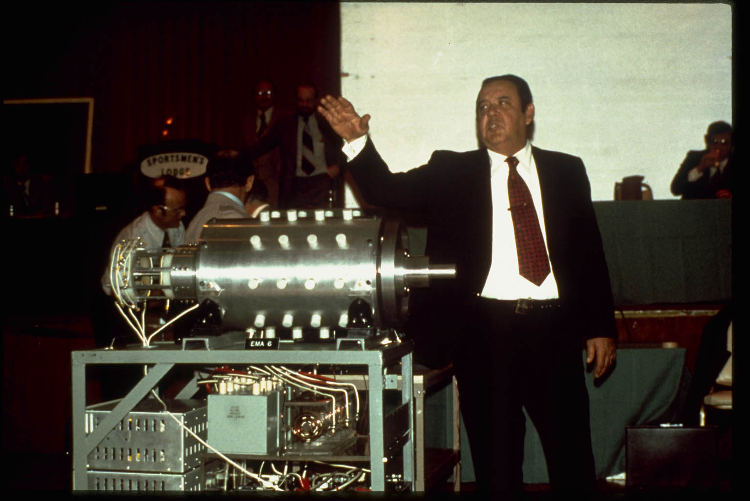
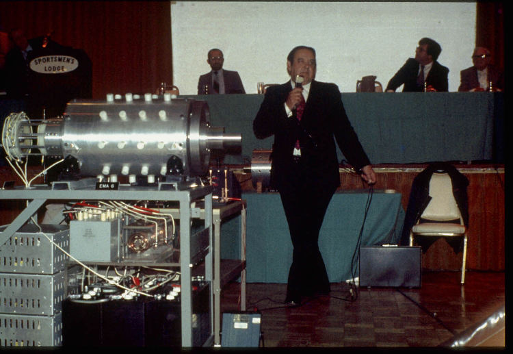
                That aluminum block was attached to the shaft and rotated along with the shaft. The particular aluminum ring was from the prototype #4 as it has only one carbon brush on the aluminum ring. The #5 prototype has three of those carbon contacts 120 degree apart of each other. You can see it better in this picture:


                The inner plastic ring was slidable and you could rotate it either way and you could do that even if motor was running. The need for a starter motor does not mean that you can't have an on the fly adjustable commutator, of course I doubt that you could just reverse the direction in a moment if the motor was rotating at say 1000RPM, you had to stop it at first. I am no expert in these systems, I just watched the video with great interest for several times
                Last edited by Jetijs; 01-04-2009, 02:34 AM.
                It's better to wear off by working than to rust by doing nothing.

                Comment


                • Phase Conjugation

                  Phase conjugation refers to time reversal of one of two waves which are then combined. This is something which is necessary to produce a higher form of energy. A good example is a non linear optics, such as a barium titanate crystal which is pumped from the side by a UV laser. A flash light beam directed onto the crystal is then reflected back at the same incidence angle, and with a convergent wave front, so that it exactly overlaps the original beam, regardless of the angle with the crystal.

                  This is harder to do electrically, but one approach is the complex coil I mentioned. There is a much easier way, using a special tuning fork, but that's not really relevant to this thread. I guess I was just rambling; I'd better slow down a little. A simple, two wire bifilar coil is all that's needed to pick up Radiant Energy, which is what we're dealing with. Better yet, just use the grids of the Conversion Tube.

                  Comment


                  • Here's a good quality pic of this prototype #6


                    Look at this picture:


                    The slip ring is just beneath that first plastic plate and I guess that small, brown pin that sticks outside, is used to adjust the timing by sliding the slip ring.
                    Last edited by Jetijs; 01-04-2009, 02:40 AM.
                    It's better to wear off by working than to rust by doing nothing.

                    Comment


                    • Electrotek; OK, you're just showing off now . Seriously though, what is your background? That sounds like laser technology of some sort.

                      You say that the simple bifilar coil will pick up radiant energy. The CSET will deliver or transmit this type of energy. So if I use a bifilar coil to drive the motor, it should receive this radiant energy from the CSET. Correct? Would the rotor also be wound bifilar? Please excuse me repeating all this, it's a necessary process for me to understand.

                      Jetjis; OK, now it finally seems to me that this motor might actually work. I've been pondering the commutator for some time and now I feel like I have a grasp of it. I wasn't able to understand being able to change the motor speed from a commutator inside the motor, but the sliding assembly answers that question. I'm still not happy about the LV diode being drawn backwards, and I have many questions about the proper power supply for this unit, but I'm getting a handle on the inductive load part. I also wonder why the diode (triode) at the LV end of the rod is shown as a tube device instead of solid state. I've heard that the other two diodes in the circuit were afterthoughts in consideration of newer SCR type switching, so that might explain the diode tube. I'm guessing the #5 prototype was using three grid tubes to drive it. Do you know if the previous versions used one or three grid tubes? Sorry to drive you crazy with all these questions .

                      Thanks,
                      Carl

                      Comment


                      • I don't know about previous motors, but prototypes #4, #5 and #6 used three CSET's. But that is not important, you can just as well use only one CSET tube, it is just that it is easier to use three because when one is fired, other tube caps have more time to charge up. If one tube had been used, the drive cap would need to charge 3x faster to get the same RPM's, this is more stress on the cap and a more powerful power supply would be needed.

                        Edit: from your posts it seems that all this radiant energy stuff is new to you. If this is true, then you definitely need to get Peters "The Free Energy Secrets of Cold Electricity" DVD or book. It will explain a lot to you. You can get it here:
                        Free Energy - Electric Motor Secrets, Bob Teal | Magnipulsion, Edwin Gray, Nikola Tesla, and other books & videos by Dr Peter Lindemann
                        This was a real eye opener to me.
                        Last edited by Jetijs; 01-04-2009, 04:18 AM.
                        It's better to wear off by working than to rust by doing nothing.

                        Comment


                        • Jetjis: OK, the video is on it's way. Thanks.

                          Later,
                          Carl

                          Comment


                          • Diode

                            @Carl:

                            My background is simple enough, I've been a professional electrician for a long time. But electricity has been my hobby much longer than that. The laser stuff came from Scientific American magazine. Anything I might have added about Q-switching and dot and dash pulses would have come from somewhere else.

                            The motor coils ARE the bifilar coil, when wired in series and placed in opposition. And the CSET will provide this kind of energy, when wired correctly, which is what we're trying to reverse engineer.

                            Here's a picture of Gray's diode:

                            ImageShack - Image Hosting :: 43328843nh9.jpg

                            This is a Thyratron, which isn't a normal diode. The patent shows this fact, since the grid is connected to the plate, rather than the cathode as with a regular vacuum tube diode.

                            The Overshoot Switch and its control cabinet is visible on the left. The wires are heavier than those going to the CSET:

                            ImageShack - Image Hosting :: 31kn7.jpg
                            Last edited by Electrotek; 01-04-2009, 07:21 AM.

                            Comment


                            • Originally posted by Jetijs View Post
                              The commutator was outside. Here is a picture of the commutator:


                              That aluminum block was attached to the shaft and rotated along with the shaft. The particular aluminum ring was from the prototype #4 as it has only one carbon brush on the aluminum ring. The #5 prototype has three of those carbon contacts 120 degree apart of each other. You can see it better in this picture:


                              The inner plastic ring was slidable and you could rotate it either way and you could do that even if motor was running. The need for a starter motor does not mean that you can't have an on the fly adjustable commutator, of course I doubt that you could just reverse the direction in a moment if the motor was rotating at say 1000RPM, you had to stop it at first. I am no expert in these systems, I just watched the video with great interest for several times
                              I think that the picture you showed,Jetijs, is only a section of the actual cammutator. By looking at this photo you can see that the assembled commutator is composed of several sections. Remember that there are wiper sections between the bearings. the bearings must be fixed solidly with the motor housing. These photos are not showing actual assembly.I would say that, that single wiper is acting as a voltage chopper/selector as in a automobile distributor. Also I believe that the three wipers you show that are on the shaft, and the single wiper, and commutator section may be part of the same commutator assembly. In fact in the bottom of the picture that you posted you can see the other three wiper assembly on the shaft of the other motor. These were used to somehow transfer power to the rotor coils. But remember they are inside the large round housing, between the bearings.

                              Update: This photo shows the section that the rotor coil's wipers rotated in. As you can see here is the slip ring segment for the rotor coils. in the back of the motor housing. These commutators were very complicated.
                              Last edited by Beshires1; 01-22-2009, 01:28 AM.

                              Comment


                              • Posting pix

                                Hi,

                                I'm gonna try to post some pictures of my Gray's tube. My first time posting here, so I may have trouble .

                                Thanks,
                                Carl
                                Attached Files

                                Comment

                                Working...
                                X