Announcement

Collapse
No announcement yet.

Self-Running Ambient Heat Engine

Collapse
X
 
  • Filter
  • Time
  • Show
Clear All
new posts

  • #91
    Thanks Peter

    Hello Peter,

    Thank you for the information, went looking got most but "Equalization Engine, Luther's Secret for Self-Fueling Air Car" and one is closed for security reason.

    Thanks Peter

    Comment


    • #92
      Alternate ambient heat engine

      Sorry People, Blueprint of design failed to post across. Peter
      Last edited by DaS Energy; 08-15-2011, 04:37 AM. Reason: Blueprint of design not retreivable

      Comment


      • #93
        Ambient heat engine alternate

        Hello People, Peter Gordon has let me know of this thread, it is my second attempt to get picture across, fingers crossed. Good luck to all Peter

        http://i1225.photobucket.com/albums/...y/DaSvalve.jpg

        Heat activated turbine largely are of Steam however recycling Co2 increases the output in the magnitude of fifty times. Our work has been to design a system that can be easily be home built and use any liquid which can be heated to a gas. The DaS Valve turbine in the atachment is complete with a parts. The hydro turbine in place is 82% efficient, it requires 9 bar of force to acheive an output of 720 watts at a flow of one litre per second, which increases by heat or flow. A comparison between recycling Co2 and water at one litre per second is water at plus 100* Celsius is 720 watts, Co2 at plus
        100* Celsius is 720 Kilowatts. The output of other liquids may be found in the phase temperature graphs of other liquids.

        Comment


        • #94
          Working temperatures Co2 Turbine

          Hello People,

          Sorry last post didnt include why it could be used as ambient heat engine, using Co2 full engine opperation begins at minus 10* Celsius and has been tested to plus 100* Celsius. So long as a minimum of 9 bar pressure is passing out of the constant supply tank all is well. Co2 is now called the refriderant gas R774. The collector/cooling tank exploits the friderant propperties of Co2 by replicating the first stage of a fridge where expansion cooling takes place.
          Peter

          Comment


          • #95
            Test Model Photo ?

            Originally posted by DaS Energy View Post
            Hello People,

            Sorry last post didnt include why it could be used as ambient heat engine,(...)
            Hello,

            In another thread you mentioned: "Working test models". Would it be possible for you to post a photo of such ?

            edit: If I understand you correctly, the "collector/cooling tank" would be where ambient-heat input takes place ? You also have something marked "Heat" near "A" and I am unsure if this is heat input, output, storage or what exactly.
            Last edited by Tom Booth; 08-15-2011, 07:39 PM. Reason: added question

            Comment


            • #96
              Dramatic Improvement ?

              I tested the new and improved check valve and recorded the results. Initially I was rather shocked by what seemed a dramatic improvement, but as the pressure built up inside the balloon my initial excitement waned somewhat.

              It should be noted however that I was only able to make a slight improvement to one of the check valves, the other is inaccessible and would have to be drilled out to be replaced.

              This did satisfy my curiosity however, that the function, or rather malfunction of the "Pump" could be improved by making a better check valve.

              Presumably, replacing both of the rather crude homemade check valves with some precision made valves would make for further improvement.

              I should point out some other factors where improvement could be made.

              The metal coffee can is too good of a heat conductor. It would be much better to use something like PVC pipe or even wood for the pump body with - possibly an aluminum top and bottom. Heat conducted through the metal body is lost heat that should instead be conducted through the air inside the "can" as it is the air you are trying to expand and contract. Heat conducted directly through the metal coffee can only tends to equalize the temperature of the air in the can loosing a great deal of the potential for expansion and contraction.

              So all in all, I would say that the results of this last test were quite encouraging as it demonstrated that improvement upon the model is possible and that it was actually the crude check valves and NOT the theory itself that led to the poor results.

              Anyway, here is the latest: Notice that my video recording is improving slightly as well. I would like to get the videos down to a smaller file size if possible but there doesn't seem to be any way to do that with the program that came with this camera.

              New Video - Stirling Pump with ONE improved check valve - does make a difference (6.49 MB MPG)
              Last edited by Tom Booth; 08-15-2011, 08:03 PM. Reason: Added 6.49 MB - indicating file size

              Comment


              • #97
                Search for video/photos

                Hello Tom,

                Sorry no photo's no videos' both were part on Photobucket but now only drawings there. DaS Energy Pty Ltd ceased two years ago and directors may still have copy so I shall make enquiry.

                In answer to your other questions. The collector/ cooling tank is just that it takes the return liquid from the turbine and the gas escaping from cylinder B after the float sphere descends opening the exhaust orfice. It has no other purpose other than for liquid collection and gas cooling.

                Heat above cylinder A is where heat may be applied or indeed the whole of cylinder A. Its purpose is only to allow the input of heat to the liquid in cynlider A it has no other purpose. The device originated as Steam driven then moved on to other liquids. The device may also be driven by compressed air through the top of cylinder A.

                Cheapest test model uses 50mm PVC pipe and a screw in reducer " polythene type" in top of cylinder B, this oddly enough makes perfect seat for the float being a squash ball. The timing pipe be no more 12mm garden hose. Compressed air is then fead through the top of cylinder A.
                Happy to help further. Peter

                Comment


                • #98
                  Originally posted by DaS Energy View Post
                  Hello Tom,

                  Sorry no photo's no videos' both were part on Photobucket but now only drawings there. DaS Energy Pty Ltd ceased two years ago and directors may still have copy so I shall make enquiry.
                  OK, thanks.

                  In answer to your other questions. The collector/ cooling tank is just that it takes the return liquid from the turbine and the gas escaping from cylinder B after the float sphere descends opening the exhaust orifice. It has no other purpose other than for liquid collection and gas cooling.
                  What would effect the cooling ?

                  Presumably, ambient, I'm guessing. Which would imply that whatever is passing through the turbine would still be above ambient temperature upon exiting into the cooling tank. Or is the cooling (of the gas) effected by the (cold ?) fluid leaving the turbine ?

                  If the heat source were also ambient, presumably applied to the tube "A" in the diagram...

                  the rest of the apparatus would have to be kept below ambient for ambient to constitute a heat SOURCE, but then the function of the "cooling tank" would either be redundant or would need some other mode of cooling - below the ambient heat source.

                  Unless of course, the turbine - removing energy - itself effected some cooling - below ambient in this case where ambient "heat" would be used as an energy source... In such a case the tank would tend towards being an additional source of heat infiltration from ambient rather than a "cooler". (Or would this be insulated ?)

                  There would, I think, need to be some modification to the design shown in the diagram for the thing to run on ambient heat, even theoretically I think. But you say you have, or have had, or someone at one time had working models of some sort.

                  At minimum I would think, if operating on ambient heat, the rest of the mechanism (other than A) would have to be thoroughly insulated to prevent heat infiltration to parts other than "A" (where exposure to ambient heat would be allowed as heat/energy input).

                  Also, the turbine would need a load applied to it to serve as an energy drain to theoretically reduce temperature, this might be assumed but is not shown in the diagram.

                  Heat above cylinder A is where heat may be applied or indeed the whole of cylinder A. Its purpose is only to allow the input of heat to the liquid in cylinder A it has no other purpose. The device originated as Steam driven then moved on to other liquids. The device may also be driven by compressed air through the top of cylinder A.
                  Taking this scinario using compressed air:

                  If compressed air goes in at A where would it come out ?

                  Without some sort of outlet, I would suspect that the turbine might work until no more air could be forced in. Eventually though, the whole assembly would become full of compressed air but there would no longer be any more flow or movement to drive the turbine as this appears to be a closed system.

                  Or if an opening were made to input compressed air, would there not also need to be another opening for the compressed air to escape, but in what way would this be any different from a common air tool or turbine running on compressed air ? Or once "charged" with compressed air, could the supply be turned off and it continue running ? Presumably if air is going in it has to come out somewhere.

                  Cheapest test model uses 50mm PVC pipe and a screw in reducer " polythene type" in top of cylinder B, this oddly enough makes perfect seat for the float being a squash ball. The timing pipe be no more 12mm garden hose. Compressed air is then fed through the top of cylinder A.
                  Happy to help further. Peter
                  A bit of Googling turns up that "DaS Energy" = "a backyard company" and or "DaS (Dad and Sons)".

                  You say test model uses PVC pipe, squash ball, garden hose...

                  Sounds like something anyone could build in their back yard. So what happened to the prototypes ?

                  Just curious - are you "Dad" or a "Son" or "Other" or is that some other DaS Energy ?

                  BTW - what is a "squash ball" exactly ?

                  edit: P.S. Never mind about the squash ball.
                  Last edited by Tom Booth; 08-17-2011, 04:43 PM. Reason: Googled Suash ball.

                  Comment


                  • #99
                    New "Stirling Air Pump" test model taking shape

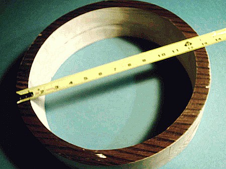
                    Wooden pump body cut from an old door with band saw and jig saw:


                    I'm using wood for a pump body as this should reduce loses due to heat conduction as opposed to metal.


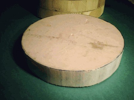
                    Displacer cut from a piece of Styrofoam house insulation with band saw:


                    This large Styrofoam displacer is actually as light or perhaps lighter than the block of plywood used in the previous coffee can model.


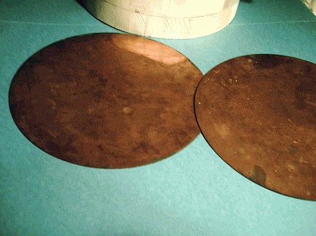
                    Copper plates for heat transfer on top and bottom:


                    These plates are about 6x larger that those used in the coffee can model.

                    This "Pump" should have about 6x the air volume and 6x the heat transfer potential over the previous model.

                    I did some calculating previously using the "Ideal Gas" equations and it seemed that the greatest expansion of air for such a device would take place on the first cycle. From then on one would be working against the air that was already compressed. Eventually the check valves would not open due to back pressure.

                    This seems to have born out in the first experiment.

                    I'm thinking therefore that what is wanted is a sufficient size "compressor" or "pump" to supply enough air flow to run a turbine with each cycle so that the air pressure can be released through the turbine immediately which would help to relieve the pressure and get more air flow out of the next cycle of the displacer.

                    I have some ideas for sidestepping this problem in other ways but before going there I think it is necessary to get a bit of a better start. But just throwing it out there for now, I think it might be possible and maybe necessary to have a kind of multistage compressor with one of these devices feeding air into another and/or some form of additional pneumatics to get higher compression but that would involve introducing additional mechanical parts which I was hoping to avoid if possible.

                    Also I thought it would be a good idea to have the displacer chamber sealed as much as possible. That is, no handle poking through the top but rather have - perhaps, a small motor - possibly inside the displacer itself so that it can raise and lower itself with just some electrical contacts providing power to the motor (like a small slot car or other very small battery operated motor).

                    The idea here is to at least get enough power or air-movement through this thing to turn a turbo-generator.

                    The turbo-generator would need to produce enough power to power the displacer motor, whatever the displacer motor or other displacer driving mechanism consisted of.

                    To start out with, I think it would be quite possible to have such a device run on ice.

                    That is, set this thing on some ice and it could, in a manner of speaking, "power itself" - (without the hand operation) in the same way a conventional LTD type Stirling can "power itself" or run on ice.

                    It is possible to keep the displacer very light while increasing the size of the machine so that at some point the energy output should exceed the mechanical input. In other words, it should take less energy to raise and lower the very light displacer than the energy gained back by the resulting expansion and contraction of air.

                    If that can be achieved then the next step would be to see if there is enough compression and/or air flow to operate some form of air-cycle cooling system to replace the ice. At that point the engine would be a true "Self-Running Ambient Heat Engine".

                    I believe that there are turbines, including some relatively easy to build Tesla turbines that can operate on very low pressure or very little air flow.

                    I don't really know as it would be possible to "tip the scales" so to speak but an air cycle cooling system does not necessarily need high compression if there is a sufficient volume or velocity of air flow.

                    I believe it is very similar to electricity where amps x volts = watts You can have either high amperage or high voltage to get the same wattage and with the air cycle you can have high compression or high velocity to get the same cooling power.

                    I'm thinking that like an IC engine. If the concept is sound, it should be able to work on any scale just as there are small working model IC engines as well as enormous IC engines for powering ships.

                    But at the same time the thing has to be big enough to overcome some practical problems like leaky check valves. I'm hoping that to some degree, size will help to overcome some of the deficiencies of the previous model.

                    I do still need to find some proper check valves as it would not be a fair test otherwise regardless of size.

                    Any ideas or suggestions for possible improvements are certainly welcome.

                    Comment


                    • Acoustic Chamber ?

                      Hi, again.

                      I have recently been thinking about Bob Neal's "Compression Unit" discussed here earlier in the thread.

                      There was some speculation that this could be some form of acoustic device.

                      I have recently been researching the so-called "Vortex Tube" and I am begining to think that the Vortex Tube and Bob Neal's Compression Unit might very well operate on the same basic principle.

                      I am curious to know if there is any specific information in regard to the relative dimensions of the Neal device, the ID or "inside diameter" and length etc.

                      Here's why: Vortex Tube Discussion (& Theory of Operation)

                      Comment


                      • Ambient or assisted heat Rotary Stirling

                        By having a turbine vane filled with cool Co2 then bringing such past a heat point causing the CO2 to expand and provide a force then carry on down to where liquid floods into the vane forcing the CO2 out and up through the cooling liquid to re-enter the turbine vane at point where the liquid is flung out back into the cooling reseviour.


                        http://i1225.photobucket.com/albums/...RROTARYDAS.jpg

                        Comment


                        • Originally posted by Tom Booth View Post
                          OK, thanks.

                          Hello Tom

                          What would effect the cooling ? - Only heat source of some kind.

                          Presumably, ambient, I'm guessing. Which would imply that whatever is passing through the turbine would still be above ambient temperature upon exiting into the cooling tank. Or is the cooling (of the gas) effected by the (cold ?) fluid leaving the turbine ? - Tom the gas passes through the cylinders A and B, liquid state only passes through a hydro turbine. - the cooling tank is similiar to expansion chamber in a fridge causing cooling, with the hot gas passing out of top of cylinder B into cooling tank. The process is one by gas pressure forcing the lquid without loss of force/

                          If the heat source were also ambient, presumably applied to the tube "A" in the diagram... - Tom the fluid passing into cylinder A is below ambient temperature.

                          the rest of the apparatus would have to be kept below ambient for ambient to constitute a heat SOURCE, but then the function of the "cooling tank" would either be redundant or would need some other mode of cooling - below the ambient heat source.- Tom you are correct, all parts other than cylinder A and the cooling tank are shaded.

                          Unless of course, the turbine - removing energy - itself effected some cooling - below ambient in this case where ambient "heat" would be used as an energy source... In such a case the tank would tend towards being an additional source of heat infiltration from ambient rather than a "cooler". (Or would this be insulated ?)

                          There would, I think, need to be some modification to the design shown in the diagram for the thing to run on ambient heat, even theoretically I think. But you say you have, or have had, or someone at one time had working models of some sort.

                          At minimum I would think, if operating on ambient heat, the rest of the mechanism (other than A) would have to be thoroughly insulated to prevent heat infiltration to parts other than "A" (where exposure to ambient heat would be allowed as heat/energy input). - Tom shading is sufficient for opperation however I do agree insulation would assist in keeping the working fluid from boiling to gas. Ether is one form of fluid.

                          Also, the turbine would need a load applied to it to serve as an energy drain to theoretically reduce temperature, this might be assumed but is not shown in the diagram. -Tom the turbine only strips off energy not heat.


                          Taking this scinario using compressed air:

                          If compressed air goes in at A where would it come out ? Tom compressed air entered at the top of cylinder A follows the gas route and passes out of the top of cylinder B into the cooling tank which would need be vented if using compressed air. -Tom absolutely correct.

                          Without some sort of outlet, I would suspect that the turbine might work until no more air could be forced in. Eventually though, the whole assembly would become full of compressed air but there would no longer be any more flow or movement to drive the turbine as this appears to be a closed system.

                          Or if an opening were made to input compressed air, would there not also need to be another opening for the compressed air to escape, but in what way would this be any different from a common air tool or turbine running on compressed air ? Or once "charged" with compressed air, could the supply be turned off and it continue running ? Presumably if air is going in it has to come out somewhere. -Tom your spot on, sorry didnt include such in post.
                          Peter


                          A bit of Googling turns up that "DaS Energy" = "a backyard company" and or "DaS (Dad and Sons)".

                          You say test model uses PVC pipe, squash ball, garden hose...

                          Sounds like something anyone could build in their back yard. So what happened to the prototypes ? Pvc pipe is simpliest build. Prototype now held with Samson Enterprises

                          Just curious - are you "Dad" or a "Son" or "Other" or is that some other DaS Energy ? I am the D in Dad and Sons Energy

                          BTW - what is a "squash ball" exactly ?

                          edit: P.S. Never mind about the squash ball.
                          Sorry about late reply shall try again to get messaging whem replies are added. Peter
                          Last edited by DaS Energy; 08-27-2011, 06:15 PM. Reason: Missinformation

                          Comment


                          • Rotary Stirling

                            Earlier in thread it was asked why no Stirling.

                            A very simple model of rotary stirling works by gas entry into vane and turbine rotates the vane which comes to heat spot causing the gas to expand and drive the turbine. When the vane has reached bottom of turbine it encounters a cool fluid chamber causing an interchange where the gas escapes into the cool fluid chamber and cool fluid fills the vane. The vane continues upward full of fluid only to be flung out like a pump when reaching top of the arc. The cool fluid displacement is replaced by the gas now cooled by rising up through the cooling fluid, and the system repeats.

                            Computer modelling only.

                            http://i1225.photobucket.com/albums/...RROTARYDAS.jpg

                            Comment


                            • Hi, It's been a while since I posted here. I wanted you (everyone) to know that I've decided to try starting an Indigogo site in order to raise the funding to actually build and test some or all of the ideas for engines that I have posted to this forum. Please consider helping to forward this project.

                              I've often wondered if it would be possible for a Stirling engine to generate a sufficient amount of heat and cold with compressed air. Exactly how much heat could be generated? I was encouraged recently when I came across a small device on YouTube that can generate more than 500 degrees F, enough to light a fire or even burn steel wool using just a small cylinder of compressed air. The Fire Piston:

                              Fire Piston Demonstration: https://www.youtube.com/watch?v=4qe1Ueifekg

                              Here is the link to this research project on Indigogo:

                              https://www.indiegogo.com/projects/e...ogy/x/10539009

                              It should be remembered also as a general principle of refrigeration that after heat is extracted from a compressed gas and that gas is then released or allowed to re-expand it then becomes very cold due to the heat having been removed.

                              I have come up with a number of designs for small model Stirling Engines that may be able to utilize these principles to at least increase the efficiency of a Stirling Engine. Whether or not such an engine could become "Self Acting" as Tesla envisioned remains to be seen, but I don't think we will know until such an engine is actually built.

                              Thanks,

                              Tom

                              Comment


                              • Hello Tom,

                                Regarding your Stirling engine work. Please remember that energy is required to compress a gas.

                                CO2 will provide energy far above any mechanically compressed gas.

                                CO2 is an Ideal Refrigerant, it flashes to gas at -40*C.

                                A Stirling engine provides both expansion force by heating and gas cooling by expansion in a vacuum.

                                Good luck with it all.

                                Peter

                                Comment

                                Working...
                                X