Announcement

Collapse
No announcement yet.

Self-Running Ambient Heat Engine

Collapse
X
 
  • Filter
  • Time
  • Show
Clear All
new posts

  • #76
    basic pneumatics

    Tom,
    Thanks for your descriptions of your interesting ideas. I would be happy to see a summary outlining the basic components of your best idea. I would study it and comment on it in detail.

    I took a look at the conversation on http://www.scienceforums.net/topic/4...rling-turbine/
    The first thing that occurred to me is that you are hungry to know what the math tells us about pneumatics. I am no expert myself despite many years of having that same hunger. After decades of starving for the facts I finally got determined to start at something like the beginning and compiled my own version of a compressed air theory for people who don't understand it and don't have anyone to teach it to them. It's called Compressed Air Power Secrets, 3rd edition (374 pages) by Scott Robertson.

    The book goes through the basic formulas relating to air compression and expansion and explains where the formulas come from, what they mean in everyday terms, so you can come to an understanding of how air works. So you can use the math to answer questions. It is kind of a freakish book because I am in no way educated to write it, but that's the whole point. All the textbook writers have the same problem. They understand their topic too well, and they can no longer remember what it was that was once difficult or needed extra explanation. As a beginner I think I captured the essence of ignorance and was able to chase it down pretty well and plug in descriptions where they were needed.

    I also work with American units like psi so that will be helpful to you.

    I'm pretty sure that Tesla's article "On Increasing Human Energy" was influential in getting a lot of people working on self-fueling pneumatic power plants in the early part of the 20th century, and then in 1930-1931 things changed, and by the end of ww2 the approach of textbooks had been redesigned to support the prerequisite system of education and discourage the do-it-yourself engineer. Because of this I am now studying books like "Calculus Made Easy" and "Calculus without Tears" so I can improve greatly on my book in the 4th edition.

    Speaking of the 4th edition, my idea called the equalization engine which is presented in the 3rd edition got disproven by me, using formulas I finally discovered in my own book, but after it had already been finished.

    This post is too long, I hope you read the whole thing...

    Scott
    Pneumatic Options Research Library
    Comment


    • #77
      Originally posted by Lutherman View Post
      Tom,
      Thanks for your descriptions of your interesting ideas. I would be happy to see a summary outlining the basic components of your best idea. I would study it and comment on it in detail.
      Hi, I am very glad to hear from you, I have been reading through quite a bit of your website. Very interesting stuff.

      I took a look at the conversation on Stirling Turbine - Science Forums
      The first thing that occurred to me is that you are hungry to know what the math tells us about pneumatics.
      Actually, the earlier thread on that site consisted largely of my asking for an opinion about the engine design and getting the reply that if I did the math I would find out that it wouldn't work.

      Well, what I discovered of late is that "the math" for something as "simple" as your common refrigerator is extremely complex, requiring something like a supercomputer just to arrive at some approximations. More often than not, such systems are actually developed by trial and error in the end.

      This engine, though, I think, very simple in principle is considerably more complex than any refrigerator. So... my current approach is to just build the thing and see what happens.

      It doesn't seem possible to directly upload images to this forum and Tripod- where the images are located doesn't allow remote linking so I will try something different.

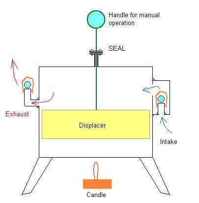
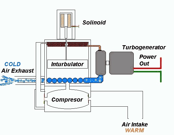
      OK, I uploaded the image to another server. This is the simplest of the designs that I think might have a chance of actually working more or less as illustrated. Perhaps not as well or as efficiently as possible with some modifications but I can use this to describe the theoretical workings of the thing:


      edit: BTW an "inturbulator" is just my own made-up name for a "displacer".

      I've attempted to explain the rationale for this name change here:

      Stirlingengineforum.com • View topic - Displacer or Inturbulator ?


      I find your writing style very easy to follow and quite illuminating and would love to read your book.

      As far as your offer: "a summary outlining the basic components... I would study it and comment on it in detail."

      Sounds good so here goes:

      Beginning with Stirling Engine theory of operation: Basically you have a sealed canister of air which is heated at one end - cooled at the other. A "displacer" (possibly just a block of wood, Styrofoam, or some other lightweight material to take up space) inside the canister is made to move inside the canister to alternately displace the air so that the air is moved from the hot end to the cold end and back. This causes the air to alternately heat up and cool and so expand when heated and contract when cooled.

      In a normal Stirling Engine a piston and cylinder are attached to the side of the canister so that as the air inside expands and contracts in the above described manner the piston is driven down the cylinder by the expanding hot air and then drawn in by the contracting cold air. The engine can operate because it takes much less energy to move the displacer than what is gained back with the piston.

      I'm not sure all that explanation is necessary but anyway, what I've done is to retain the Stirling engine displacer and the chamber that it moves in but have done away with the entire piston and drive mechanisms - connecting rod, flywheel etc. and instead added just some check valves to the displacer chamber. Otherwise the action of the displacer and the resulting expansion and contraction, the alternate heating and cooling of the air inside the chamber is identical to a conventional Stirling Engine.

      Here is another even simpler illustration:


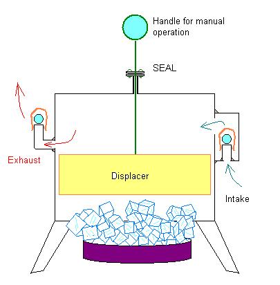
      The above is a very simple hand operated "Stirling" type air pump or compressor. By moving the blue handle up and down so as to move the displacer inside the chamber up and down the air inside the chamber is made to alternately heat up and cool down and so expand and contract.

      In expanding, some of the air escapes through the check valve on one side, but in contracting a partial vacuum is created which draws air in through the other check valve on the other side. In other words you have a HEAT powered "air compressor" or air "pump". It takes very little effort to move the displacer up and down and yet theoretically, a great deal of air flow or compression might be generated by this means.

      This should also work using ice instead of a flame. In such a case the "engine" or pump or "compressor" would be operating by the ambient heat in the air or in either case by the "temperature differential" created by either the flame or the ice or both simultaneously - a flame applied to one end of the chamber with ice applied to the other. The greater the temperature difference between one end of the chamber and the other the greater the potential air flow or "compression".

      So, what we have is a compressor that operates more or less directly on a temperature differential just as a Stirling Engine operates on any source of heat or "cold" - that is, ambient heat using a cold "Sink" to create the temperature differential.

      Now, given a means of compressing air, we then have the means of powering a heat pump. Do we not?
      Last edited by Tom Booth; 08-05-2011, 06:14 AM. Reason: define "inturbulator"

      Comment


      • #78
        The above compressor running on ice or in other words using ambient heat as an energy source:


        Simply move the handle up and down, which is very easy as the displacer is very light weight and there is very little resistance. Note that the displacer is not "pumping" the air directly. The displacer does not touch the chamber walls. The air simply flows freely around the displacer alternately coming into contact with the hot or cold end of the chamber and so expanding and contracting.

        The expansion and contraction of the air itself is what acts as a kind of invisible piston to drive the air through the chamber with a great deal more force than the force needed to move the displacer.

        Now getting back to the first illustration:


        The compressed air generated is now being used to operate a simple "Air-Cycle" heat exchanger.

        The heat exchanger is put right INSIDE the displacer chamber and acts as a replacement for the candle flame and ice.

        Theoretically now, the turbine driven by the compressed air flowing through this system should, if attached to a generator, be able to produce more electricity than what would be needed to operate the displacer if that were driven by a small motor. The excess energy from the turbine could be used for other purposes such as charging batteries, lighting light bulbs, helping to power the electrical grid or whatever.

        I am not underestimating the effectiveness of a simple air cycle heat exchanger as at one time I worked in an engine shop and a fellow worker accidentally froze his finger to the side of an air powered impact wrench. The air escaping from the port on the side of this air tool was so cold that it froze part of his finger solid which subsequently broke off. That is, part of his finger stuck frozen to the air tool and broke off like a piece of ice and he had to be taken to the hospital and was out on disability for some time as a result.

        So simply compressing and then re-expanding plain old air through some sort of pneumatic tool causing the air to do work as it expands can create incredibly cold temperatures. This can be seen by simply observing that a mechanics air tool will sometimes form frost around the exhaust port during ordinary use.

        When my coworker froze his finger to such a tool he was removing a series of heavy bolts from an engine but it was nearly 100 degrees Fahrenheit in the workshop.
        Last edited by Tom Booth; 08-05-2011, 04:58 AM.

        Comment


        • #79
          Here is a somewhat more elaborate design. (animated Gif) The simple displacer has been replaced by a "regenerator" which is simply a mesh of stainless steel wool type material used to temporarily retain heat commonly used in Stirling Engines. Rather than the air passing AROUND the "displacer" it simply passes directly THROUGH the "regenerator".

          There are also some additional coils intended to reclaim heat and to augment the ability of the turbine to produce additional cold or more extreme cold if need be. I have a few other designs intended to enhance the performance of the engine, (assuming that it can work at all) but have not reduced these ideas to online drawings or animations as yet, however in any case the basic principle of operation is the same:


          I hope all this helps to convey some idea of how this "Ambient Heat Engine" is supposed to operate.

          I've had this on the shelf or "back burner" for some time but am now in the process of actually trying to build the thing here in the workshop.

          BTW "insolation" is not anything unusual, just a typo. Should be Insulation.
          Last edited by Tom Booth; 08-05-2011, 05:40 AM. Reason: added BTW

          Comment


          • #80
            Fluid Diodes

            I was just reading a page on your website that mentioned "Fluid Diodes" and am now wondering if these would be as efficient or more efficient than plain check valves or leaf valves. It would certainly be wonderful if I could eliminate a few more moving parts!

            Check valves can be less than 100% efficient as some back pressure / leakage is actually necessary in order to close the valve. Does a "Fluid Diode" work as well or better than a check valve or leaf valve.

            I know from working in an engine shop that one of the most common problems with two-cycle engines was the leaf valves failing to close all the way due to becoming slightly bent. Ordinary check valves can get stuck.

            If these Fluid Diodes actually work very well I think it would be great to use them in this engine. A few less moving parts to potentially break down, get stuck or wear out.

            Comment


            • #81
              In your concept you return the heated air into the heat exchanger that heated it in the first place or am I misunderstanding the process.
              Last edited by broli; 08-06-2011, 10:46 PM.

              Comment


              • #82
                Hi Tom,
                I hope you will keep this thread active, and post updates & pics of your build.
                I have much interest in Stirling engines as well as Tesla turbines. I too have
                been thinking, for some time along the lines of combining the two, but they
                both would require machining beyond my ability at this time.
                If I may, I would suggest the elimination of the coils in the ambient intake, as
                well as in the cold exhaust, these would cost a great deal in efficiency at
                the turbine by lowering the turbine intake temperature.
                Tesla said that the temps at the exhaust of his turbines would be 30% less
                than at intake, and also if the exhaust of the turbine was then fed to the intake
                of a second turbine, with twice as many blades, another 30% reduction of
                temps would be achieved and you would also gain 50% in HP!
                Perhaps these delta-T's at your displacer would be enough.
                I could very well be way off on this, but these are my first thoughts.
                Wish you good luck on your build, Gene

                Comment


                • #83
                  Originally posted by broli View Post
                  In your concept you return the heated air into the heat exchanger that heated it in the first place or am I misunderstanding the process.
                  Well,... sort of MAYBE but not really.

                  The idea is to move some air mass through the system until it can reach the turbine.

                  The idea isn't really to move the heated air into the heat exchanger but to, as far as possible move fresh warm ambient air from the atmosphere - already heated by the sun - into the heat exchanger so as to extract the heat with the intent of converting the heat or "temperature differential" produced by the heat exchanger into a pressure differential.

                  Some of the heat, if we are lucky, may be "recycled" or conserved for "re-use", though theoretically, I'm not really sure to what extent that is possible, if it is possible at all.

                  That is, I don't think it is possible to actually "REUSE" heat. Heat that has been "converted" into pressure is no longer heat I don't suppose. (or is it ?)

                  In this configuration:


                  At one point I had an actual diaphragm separating the upper "displacer chamber" from the lower "compressor chamber" because what is really wanted is to pump just ambient air into the system.

                  The displacer chamber could actually be sealed so that no air goes in or out of it. But, I figured, diaphragms can rupture. So what if it did ? Would it make a difference ?

                  There is air on either side of the diaphragm. Does it matter at all if there is some mixing between the two ? I kind of doubt it. It might even be of some benefit in terms of "recycling" or reclaiming or "regenerating" some extra heat in the manner that you describe or observe though that is kind of incidental.

                  I did place the "heating" coils at the top to conserve heat as hot air naturally rises.

                  Most Stirling engines have the heat source at the bottom for the same reason - heat rises, if the heat source were at the top in a conventional Stirling Engine it would go up into the air instead of into the engine , but in this engine the heat is contained in or emitted from, coils inside the displacer chamber so the heat source can be at the top which will have an additional heat conserving effect I think.

                  Depending on the location of the ports, What you describe may happen to some extent but the general idea or goal I think is to turn AMBIENT heat into pressure. If the heat, or rather, if unconverted heat can be "recycled" or conserved to create more pressure - all the better.

                  The idea is to keep the heat that has not been converted into pressure recycling until it IS converted into pressure.

                  At times I've referred to this "engine" as a "heat wringer". The idea being to squeeze or "wring" as much heat as possible out of the air and convert that heat into some other form of energy. The thin coils at the top (red) are where the heat is "squeezed" from the air.

                  Generally, once the engine is in full operation and cycling, it should turn a temperature differential into a pressure differential which pressure at the turbine nozzle should become mostly velocity to turn the turbine and finally the velocity into electrical energy as the turbine turns a generator.

                  It might be beneficial to allow some ambient heat back into the system just before the turbine, perhaps with some form of pre-heating unit to re-expand the air with ambient heat just as it enters the nozzle which might result in more violent expansion through the turbine. Some sort of heat regulator at that point might be needed so as to maintain a balance according to whatever load is on the turbine, how cold the air leaving the turbine is etc.. If it is cold enough or too cold a bit of heat could be allowed back in giving the turbine a greater potential power output - maybe, but that is getting a little ahead of things I think. In that case though an additional check valve or "fluid diode" might be needed to prevent back pressure.

                  At one time I also called this thing a "liquid Air" turbine. The idea being that by the time the air reached the turbine it would actually be so cold it would liquify, the turbine running on the violently expanding liquid air dripping from the nozzle.

                  I don't think I'll be achieving that with a small home built model, but it is a kind of theoretical possibility I guess, if enough heat were removed.

                  Another way the heat might be "recycled" is with the "regenerative displacer" - basically a standard Stirling Engine regenerator that temporarily stores and then releases heat right inside the displacer chamber.

                  So yes, in a way, the idea is to "pump" or "compress" the air with heat and do so, as far as possible without loosing or wasting any heat in the process.

                  Inevitably SOME heat will find its way to the cold pipes or coils at the bottom which heat will be carried away and lost. We want to keep this "loss" to a minimum in as many ways as possible, I think, so that as much of the heat as possible is eventually converted into electricity.

                  I actually have several variations of this engine so the answer might be yes or no depending on which design we are talking about.

                  Of course if a diaphragm were actually used the answer would be no, but I'm trying to eliminate as many redundant moving parts as possible so - I guess its a Maybe. - LOL

                  I'm probably over-explaining, I hope some of this makes sense.

                  Comment


                  • #84
                    Originally posted by gene gene View Post
                    Hi Tom,
                    I hope you will keep this thread active, and post updates & pics of your build.
                    Sure, though the going may be rather slow. I don't get much time to work on this thing, but, maybe if I spent LESS TIME on the computer...

                    I have much interest in Stirling engines as well as Tesla turbines. I too have
                    been thinking, for some time along the lines of combining the two, but they
                    both would require machining beyond my ability at this time.
                    I got kind of lucky in that I came here to use the shop space, knowing only that there were some woodworking tools, But as it turned out there is also a nice metal lathe, though I'm going to have to learn how to use it.

                    I splurged and bought a cheap brazing torch from Home Depot a few days ago. The alternative was to braze using a deep-cycle battery and some carbon cores from some flashlight batteries for creating the brazing arc. I've done that before and it actually does work.

                    If I may, I would suggest the elimination of the coils in the ambient intake, as
                    well as in the cold exhaust, these would cost a great deal in efficiency at
                    the turbine by lowering the turbine intake temperature.
                    I'm afraid that without the heat exchanger coils there would be no temperature differential to run the thing. Turbines, as far as I know, run on pressure/velocity/flow not temperature, though, when talking about "internal energy" this gets kind of fuzzy.

                    I'm not sure about all the hows whys and wheres but internal to the air molecules heat and motion are somehow the same thing. The energy in a gas is actually kinetic energy or motion. "Heat" is just our subjective experience of fast moving molecules transferring kinetic energy to our skin.

                    So,... velocity such as being emitted from a nozzle in a turbine is a kind of twofold kinetic energy. There is the Macro-"external" kinetic energy as well as the micro-"internal" kinetic energy striking the turbine blades. What we generally refer to as "heat" in hot air is the Macro-kinetic energy in the air. We want to turn that into velocity and in the process make the air cold so that we can force some of the micro-internal energy out of the air, which normally doesn't ever happen. It is the additional internal energy that we are squeezing out that makes this thing work makes it "Self-Running". There is PLENTY of so-called "internal" energy in the air but it is normally not available.The only way to make it available, I think, is to cool the air below ambient BEFORE it reaches the turbine, that is, take out all the "external" energy so that the turbine will be powered by the so-called "internal" energy, which is what we are really trying to get at.

                    In other words, we use all the "external" or Macro-Heat energy to power the "compressor" to create the pressure/velocity to run the turbine which needs to run BELOW AMBIENT so as to extract the "internal" micro-kinetic energy.

                    As far as I can figure, "internal" and "regular energy" in a gas is just a matter of the gas being above or below ambient temperature. It seems to be arbitrary or relative. But in practical terms, I think it is necessary to get the air below ambient temperatures before it enters the turbine so as to extract that EXTRA energy often referred to as "internal" which will cool the air well below ambient so as to provide a continual heat "Sink" such as Tesla described in his article.

                    Tesla said that the temps at the exhaust of his turbines would be 30% less
                    than at intake,
                    That is, I believe, under "NORMAL" conditions. That is, without the turbine being insulated.

                    In the liquefaction of gases the turbines are kept very very very well insulated and this allows for much colder temperatures. The gases are also pre-cooled with the cold air leaving the turbine so as to reach even colder temperatures - cold enough to liquify the gas.

                    By insulating the turbine the expanding gas entering the turbine cannot use any external heat from the environment to do the expanding and so it is forced to draw upon its latent "internal" heat to do the expanding. This is the "Trick" to get the air to give up that EXTRA heat. You get the "internal" energy out which is converted into electricity and at the same time you get your "Sink" which creates the flow of energy from the surrounding ambient.

                    But in this engine, unlike in the liquefaction of gases I think there will be both the "external" heat energy which has been converted into pressure / velocity and also the extra "internal" energy gained. In general, when a similar process is used to liquify gas - ordinary electrically driven compressors are used which consume a great deal of energy, by comparison, the energy extracted by the turbine is negligible, maybe 25% 0r 30% of the energy "wasted" by the compressor, but in this case the heat from the air is also doing the work of the compressor. This heat used for compression may, in a sense be "wasted" but the 20% or 30% left over and used to drive the turbine is clear gain.

                    So although the turbine may be "less efficient" running on cold air it is running on the "internal" or below ambient temperature "kinetic" energy we are trying to get at which is what makes this engine theoretically "Self Acting". To maintain a cold "sink" to draw in energy we have to "throw away" a great deal of heat/energy in the process.

                    This is how the underwater "Tank" in Tesla's illustration is kept "pumped out" by dumping a lot of energy to create a "sink" for the ambient energy to flow into. Once the flow of energy is started - if it can be maintained - we can extract some energy from that flow but we have to keep bailing out the tank in the process by operating at cold (below ambient) temperatures.

                    and also if the exhaust of the turbine was then fed to the intake
                    of a second turbine, with twice as many blades, another 30% reduction of
                    temps would be achieved and you would also gain 50% in HP!
                    Well, that is something to think about. More cold, greater temperature differential, more horsepower. Sounds good to me.

                    Perhaps these delta-T's at your displacer would be enough.
                    I'm not at all sure what you are referring to by "delta-T's at your displacer".

                    Umm... Google turns up, in relation to chemistry: "Delta T is the change in temperature of the system which occurs when heat ENERGY is absorbed/emitted by the reaction."

                    I'd be guessing you are referring to the heat exchanger coils. (???)


                    I could very well be way off on this, but these are my first thoughts.
                    No problem, I appreciate the input. I'm probably "way off" myself. There have been a number of failed "perpetual motion" machines in my parents basement ever since I was a teenager. If this thing actually works I would see it as something of a miracle.

                    Wish you good luck on your build, Gene
                    [/QUOTE]

                    Thanks, I think I'll probably need it. Feel free to beat me to the punch and save me the trouble. If whatever I cobble together doesn't work maybe someone else's design will.

                    Somehow though, this little toy convinces me that its possible:

                    YouTube - "Dippy Bird" generating electricity

                    It is also a heat engine that turns a temperature differential into a pressure differential and produces enough excess energy in the process to maintain its own "sink" - and then some.

                    Comment


                    • #85
                      Originally posted by gene gene View Post
                      (...) I would suggest the elimination of the coils in the ambient intake, as well as in the cold exhaust, these would cost a great deal in efficiency at the turbine by lowering the turbine intake temperature.
                      Tesla said that the temps at the exhaust of his turbines would be 30% less than at intake,...
                      On second thought...

                      I believe what Tesla was referring to, as I think I recall reading it somewhere, was driving his "Tesla Turbine" or bladeless turbine with steam.

                      The steam, of course, enters the turbine extremely hot. I recall Tesla talking about or demonstrating to a reporter or something that it was possible to put ones hand directly into the "exhaust" from the Tesla steam turbine. This was unheard of for a regular steam turbine - attesting to the efficiency of the Tesla Bladeless Turbine.

                      The main reason I was became interested in the Tesla Turbine for this project was not efficiency but ease of construction. People are building Tesla turbines out of old hard drive platters and such. Also, the Tesla Turbine is very quite which would be a consideration if this thing ever found its way into residential use.

                      Anyway, lets say the coils were eliminated. It would still be possible to get ambient heat, though less concentrated, but if some pressure to run the turbine could be generated by ambient heat alone - then there would also be some cold air output from the turbine. Originally, or at one point I actually had the turbine itself INSIDE the bottom of the displacer chamber - so the cooling "coils" could be eliminated in such a manner. Actually my main reason for doing otherwise was simply due to the fact that an "exploded view" was easier to draw for illustration purposes. The "actual" engine running in my head was much more compact with the turbine in-line with a rotary displacer and a fan all on the same shaft. The drawings are a "simplified" exploded view of the basic concept using the simplest type of LTD type displacer that can be seen on YouTube running on an ice cube and such.

                      Anyway, after giving it some additional thought, what you describe might very well work.

                      I thought that the additional heat from some heat exchange type coils might add some additional heat ABOVE AMBIENT - to make the "compresor" work more efficiently. There is, or may be a trade-off though. The more heat used to drive the compressor the less hot-air to drive the turbine, maybe, though I also think it would be possible, - since the heat source is free and virtually unlimited - to use some heat to run the "compressor" and then just add the heat right back - drawing from the ambient surroundings again before the air is released through the turbine.

                      From what I've been reading on Scott's Pneumatic Options website recently the old air cars used in mines or some old regenerating air powered locomotives drew heat from the air repeatedly is several stages.

                      So maybe rather than concentrating the heat with a heat exchanger, the way to go might be to introduce the ambient heat in stages, use some, then allow more in along the line somewhere and use a bit more.

                      There are several different variations of the same general concept. What would work, or what would work most efficiently in actual practice, I think is anybody's guess.

                      I think the first thing I will try to actually build here is just the simple heat driven - hand operated "compressor" or "pump" illustrated earlier. - just a tin can perhaps, with a couple check valves, a seal and a hand operated displacer, just to see if heat really can be converted into pressure in the way I am imagining it can, from a candle flame and/or some ice - see if such a device can at least blow up a party balloon or something, if so, put a small tank and a gauge on it and maybe get some actual numbers to play with and if that works go from there.

                      If such a heat driven "compressor" actually works at all, there is some hope for the rest, as this "compressor" is really the only thing that distinguishes this thing from a "bootstrap" Air-Cycle cooling system where the turbine is used to only REDUCE the load on a more conventional compressor.

                      The other components have already been proven and are in relatively common use already. This compressor certainly resembles a pneumatic pump, hydraulic jack, "pulse pump" etc. but I don't think anyone has actually used ambient heat to compress air in any way before. Maybe they have in some one of those old air cars or other engines but the method was apparently lost as far as I know - if it ever existed. It seems to simple not to have been thought of before now.

                      Comment


                      • #86
                        regenerative compressor

                        About the possible use of a "regenerator" or regenerating displacer instead of a plain displacer.

                        Here is what Wiki says about it:

                        "The regenerative heat exchanger gives a considerable net savings in energy, since most of the heat energy is reclaimed nearly in a thermodynamically reversible way. This type of heat exchanger can have a thermal efficiency of over 90%, transferring almost all the relative heat energy from one flow direction to the other. Only a small amount of extra heat energy needs to be added at the hot end, and dissipated at the cold end, even to maintain very high or very low temperatures."

                        Regenerative heat exchanger - Wikipedia, the free encyclopedia

                        This claim seems somewhat debatable. I've read from the posts of several Stirling Engine model builders that the regenerator makes little if any difference in engine performance.

                        Be that as it may, in THEORY, the regenerator would allow the heat used to expand the air in the displacer chamber to be re-absorbed from the air by the regenerator then re-released to once again expand the air in a continual cycle. With the check valves capturing the expanded air this should theoretically result in a very efficient "compressor".

                        Besides this possible mode of regeneration there is also the possibility of reclaiming heat by other means (left over heat in the heat exchanger can be reabsorbed by the incoming ambient air increasing the temperature of the air entering the system above ambient) and since this is an "open" system, fresh additional heat is constantly being drawn in from the surroundings.

                        This is why I concluded that a parabolic concentrator to focus solar energy on this machine was unnecessary. If it worked as I had imagined the machine would concentrate plenty of solar energy directly, or rather indirectly straight from the air - even after the sun went down.

                        Could too much heat accumulate ? Perhaps, but this could be remedied by allowing a greater flow of air through the turbine and by increasing the load on the turbine. I think.

                        Comment


                        • #87
                          Originally posted by gene gene View Post
                          Hi Tom,
                          I hope you will keep this thread active, and post updates & pics of your build.
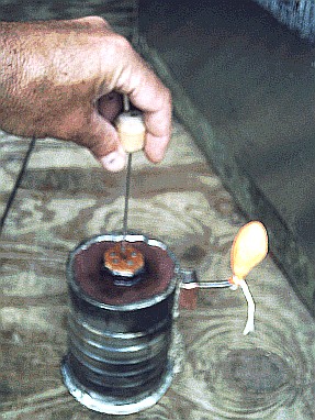
                          So far I have finished this "Simple Stirling Air Pump":

                          Here is the drawing from earlier:


                          And here is the model I just finished putting together:


                          I figure that if this crude tin-can model using old skateboard ball-bearings for check valves can inflate a balloon then the idea is probably solid enough to go ahead and build something more elaborate.

                          The idea here is to strip a Stirling Engine of all of its moving parts, the piston, crank shaft, flywheel etc. and replace them with a pair of check valves retaining only the displacer, which IMO is the "HEART" of a Stirling Engine.

                          Inside a Stirling Engine Displacer Chamber the air is heated and cooled and so made to expand and contract. What I'm trying to do here is to use check valves so as to turn the "alternating" expansion and contraction into a linear flow that can be used like any compressed air to blow up a balloon or to power a turbine or an air-cycle heat exchanger.

                          In my mind this component is the key to a potential "self running ambient heat engine".

                          If this "compressor" works, you then would have a kind of air-compressor that runs on a temperature difference - like a Stirling Engine but with fewer moving parts than a conventional Stirling Engine.

                          If this component doesn't work for some unforeseen reason then the whole idea is a bust IMO.

                          Anyway, I'll try and figure out this digital camera while the epoxy is drying and if possible post a video of the historic event. (Success or Failure) within the next few days.

                          Comment


                          • #88
                            Stirling Pump

                            Well, here is the video of my model sitting on a bowl of crushed ice:

                            Stirling Ice Pump Video (7.19 MB mpg video file)

                            It appears my crude homemade "check valves" were not working.

                            Otherwise it appears that the expanding and contracting air IS expanding and contracting the balloon but the valves are not sealing the air inside the balloon so the air is not building up and inflating the balloon as intended.

                            I will try making some more effective check valves, or purchase some.

                            It also appears that this "Tin Can" compressor is not moving very much air at all, but that is more or less as expected. I may try a different design with more surface area at the top and bottom and a thinner - wider displacer, more along the lines of an LTD type Stirling (and with some better check valves).

                            Comment


                            • #89
                              New check valve test

                              Hi, just to make sure, before going any further, I made some modifications to the one check valve that is accessible:


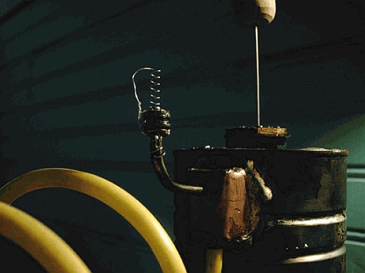
                              I affixed a neoprene washer to the end of the pipe and added a spring (The washer is from a faucet repair kit and the spring is from a pall point pen).

                              Testing this, by blowing some air through the valves using a piece of tubing attached to the lower "intake" valve, this new arrangement does seem to have helped some. That is, the valve seems a little more responsive and seems to possibly be making a better seal.

                              I have rather thoroughly covered the seal and spring with "Goop" to hold them in place. I will need to let this dry before having another go at seeing if this works any better at all.

                              Comment


                              • #90
                                Tesla Valve Idea

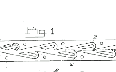
                                While waiting for the glue to dry on the valve (again) I was researching check valves in general, as this seems to be a potentially troublesome component, I came across the Tesla Patent for his "fluid diode" or something similar he called a "valvular conduit":

                                Tesla Valve - Google Patents

                                It looks like this:


                                I thought this seemed rather complex and probably quite difficult to manufacture not to mention somewhat less than perfect. Tesla describes it in the patent as a somewhat "leaky valve".

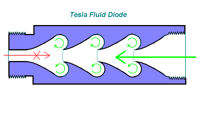
                                Anyway, after studying this for a while and thinking about it I came up with what might be a similar but possibly better design that should be relatively easier to make and I'm thinking that it might even be more effective. What I came up with looks like this:


                                I'm guessing that once a flow is initiated in one direction a series of Toroidal Vortices will be set up that should facilitate flow in one direction but seriously inhibit flow in the other.

                                I don't know as it will work but it might be possible to make simply by heating and crimping some plastic tubing.

                                I'm also thinking that this might even reduce drag or friction in the desired direction as opposed to a straight pipe or tube due to the motion of the vortices which once set to spinning would act almost like little air ball-bearings.

                                My reasoning is that this looks like a serrated knife which cuts better than a straight blade. It also resembles waves on the ocean and/or sand "waves" on the desert formed from wind. On the principle that everything in nature follows a path of least resistance - one might assume that this shape and the circular eddies formed reduce wind resistance on the surface of the water or sand.

                                Tubes of this shape might just reduce the resistance of a fluid flow through the tube in the desired direction while impeding flow in the opposite direction.

                                Anyway, from reading the patent it appears that Tesla designed this "valve" with his "Self Acting Engine" in mind, as he mentions its use in connection with one of the components of that engine which he developed his "mechanical oscillator".

                                He states also that this valve is intended for use where there is a pulsating flow or a potential for a rapid oscillation in a flow, which would actually be the case here - the alternating expansion and contraction of gas or air in a heat engine. Tesla states that his valve is ideal for such a circumstance.

                                I'm thinking though that the toroidal vortices set up by the alternative design would create longer lasting eddies or doughnut shaped swirls - like smoke rings that would be, to some degree, self sustaining.

                                In one direction the air would be almost "pulled through" the center of the doughnut shaped vortex while in the other direction, once the vortex was set up, there would be an opposing flow - like trying to squeeze through a ring of spinning tires.

                                While in one direction the spinning would be an assist in the other a direct impediment.

                                Comment

                                Working...
                                X