Announcement

Collapse
No announcement yet.

Self-Running Ambient Heat Engine

Collapse
X
 
  • Filter
  • Time
  • Show
Clear All
new posts

  • Well this is interesting I suppose.

    Someone had posted a thermal image video of a lamina flow type Stirling engine to YouTube quite a while back.

    There were some comments on this video to the effect that it was quite surprising that it appeared that very little if any heat at all was migrating to the cold "sink" end of the engine.

    The "heat flow" actually appeared entirely static. Basically it appeared that the heat was in effect being "destroyed" or converted into mechanical energy before it went anywhere in the engine. The cold "sink" end of the engine did not get hot and then dissipate the heat. It just stayed cold, apparently at ambient.

    I posted this video several times in the past in various forums in an effort to show that heat in a Stirling Engine did not actually make it to the "sink", and that therefore Tesla's ideas were actually quite practical and "do-able"

    That is, an ambient heat engine running "on ice" or a "cold hole" could potentially run forever as the ambient heat would not be going THROUGH the engine but would rather be entirely converted into mechanical energy.

    The "Laws" of thermodynamics dictate that SOME heat absolutely MUST flow through the engine, but personally I DO NOT BELIEVE THAT!!!!

    It is important when considering these issues to understand how "thermal efficiency" is actually reckoned.

    A Stirling Engine could be entirely "SELF ACTING" it could run "on ice" indefinitely or even chill the ice colder than freezing indefinitely and perhaps even produce a bit of power to light a light bulb or something and "THEY" (the staunch proponents of the 2nd law of thermodynamics) would still say that such an engine was "inefficient". maybe it would only be 2% efficient if it could light a LED and run "forever". It could actually run forever with no external energy output. Just keep itself running and it would be 0% efficient, but this would still be a "Self Acting Engine".

    Thermal efficiency is therefore not really an issue that prevents a heat engine from being "Self Acting".

    I went to find this video to post here, but unfortunately it no longer exists.

    This is the link where it had been previously located.

    https://www.youtube.com/watch?v=PflY-AFp15c

    [VIDEO]https://www.youtube.com/watch?v=PflY-AFp15c[/VIDEO]

    Here is a more recent video I found of a different type of Stirling Engine. The Temperature difference is not so prominent in this video as it appeared in the other video of the lamina flow type engine but I suppose it is still interesting.

    [VIDEO]https://www.youtube.com/watch?v=dioZjZ4gv78[/VIDEO]

    I think these "Toy" LTD Stirlings are "less efficient" than the Lamina Flow engine type. Heat rises. Hot air rises. Therefore I think this newer video of the LTD engine would show the effect I'm talking about more clearly if it were running on ice rather than a hot cup of coffee.

    Ice underneath the engine that is with ambient heat on top. rather than the heat on the bottom.
    Last edited by Tom Booth; 08-28-2016, 08:43 PM.

    Comment


    • Originally posted by Peter Lindemann View Post
      Tom,

      YES, I first suggested that the Drinking Bird was an embodiment of Tesla's "Self-acting Engine" in a lecture I gave in 2012. The Drinking Bird was invented in China sometime before 1922, when Albert Einstein reported being amused by one in a shop in Shanghai. Whether the inventor knew of Tesla's idea of an atmospheric heat engine is not known. What is known is that he solved Tesla's criteria for creating an artificial "cold spot" that could constantly replenish itself using a natural process, thereby allowing the device to draw in heat from the ambient air and channel it through the device and produce mechanical energy in the process. So, evaporation of water creates the cold spot, and the confined dichloromethane expanding and contracting changes the balance point of the Bird so that it alternately becomes either "top heavy" or "bottom heavy," creating its "drinking motions" on its stand.

      The other important lesson of the Drinking Bird is that it shows that even small temperature differentials can be sufficient to demonstrate the complete cycle in a well engineered device. I own a couple of Drinking Birds and have played with them quite a bit. Interestingly, they work better with warm water than with cold water. They work best on a warm day with low relative humidity. On days of moderate humidity, once the Bird's head is wet, it will bob up and down for up to 30 minutes without needing anymore water. Under most other conditions, the Bird works better when drinking from a cup of isopropol alcohol, since it evaporates more easily and accentuates the cooling process. Continuous use of isopropol alcohol is not recommended however, because it is not good to breathe and may degrade the glue holding the red felt to the Bird's glass head.

      The point is, Tesla was right and it IS possible to build an engine on these principles. The question is: when is humanity going to perfect this machine at an industrial scale and provide itself with unlimited energy from the Sun, 24/7?

      Peter
      I don't personally have the resources to do any large scale manufacturing, but what I can do, and am currently in the process of doing is to perfect a small working model engine.

      I would like to produce and distribute as many of these small model engines as possible.

      I believe that if a principle is sound, it can be done on any scale.

      What I imagine would be something like a small "self acting engine" that could sit on someones end table and run a night light or a table lamp, or possibly serve as a cell phone recharging station.

      Anyone who sees such a thing would immediately see the possibility of scaling it up to power a home.

      Something not very different from or any bigger than the little "toy" Stirling Engines already available on the market.

      Just put an ice cube in the bottom to get it started.

      Something similar to this:


      Stirling Charger V 2.0 - Charge your phone with a candle!| Interesting Engineering

      But not needing a candle.


      Just by way of a warning. There is some similar project on Kickstarter alleging to be making or planning to produce a Stirling Engine cell phone charger.

      As far as I can see this is a total scam IMO. the thing looks nothing like any conceivable working Stirling Engine. I don't believe that it could possibly work as advertised and would not put any money into it, though thousands of people obviously already have. View the updates/comments. backers of this project are pissed off and want their money back.

      https://www.kickstarter.com/projects...ck/description
      Attached Files
      Last edited by Tom Booth; 08-28-2016, 09:13 PM.

      Comment


      • How About This?

        Hey Tom,

        I love the way you think. So, this is sort of what I think you are talking about, right?

        A Stirling Engine made with a rotary displacer made of Styrofoam running a "piston" made from a balloon (or plastic bag) held in a small "bellows" type of structure. If the hinge on the bellows structure was hanging downward, it could rock back and forth across a balance point and act like a pendulum while driving the crank shaft. In this way, 98% of the momentum in the moving parts could be conserved. This "proof of concept" design would need very little critical machine work and could be scaled easily from the size of your hand up to the size of your kitchen with very few modifications.

        The top of the rotary displacer is the hot side, which can be painted black to absorb more frequencies of light and convert them into infrared, and under the bottom of the displacer is a small, highly insulated box (at least R-200) to hold your initiating ice cube. The insulated box should be painted white of covered with aluminum foil to act as a "radiant barrier" to heat absorption. Larger models would have the displacer half buried underground.

        If you are right about the ice cube never melting, and I agree that by tweaking the phase relationship between the power piston and the displacer you should be able to produce some cooling at the end of the stroke, then this could be the beginning of a practical design!!

        LOL. Here is a post I made to another thread on Stirling Engines in 2014. http://www.energeticforum.com/renewa...tirling.html#7 Its almost the same idea, except it is designed to run on solar heated water.

        Awesome!

        Peter
        Last edited by Peter Lindemann; 08-29-2016, 08:43 PM.
        Peter Lindemann, D.Sc.

        Open System Thermodynamics Perpetual Motion Reality Electric Motor Secrets
        Battery Secrets Magnet Secrets Tesla's Radiant Energy Real Rain Making
        Bedini SG: The Complete Handbook Series Magnetic Energy Secrets

        Comment


        • Originally posted by Peter Lindemann View Post
          Hey Tom,

          I love the way you think. So, this is sort of what I think you are talking about, right?

          A Stirling Engine made with a rotary displacer made of Styrofoam running a "piston" made from a balloon (or plastic bag) held in a small "bellows" type of structure. If the hinge on the bellows structure was hanging downward, it could rock back and forth across a balance point and act like a pendulum while driving the crank shaft. In this way, 98% of the momentum in the moving parts could be conserved. This "proof of concept" design would need very little critical machine work and could be scaled easily from the size of your hand up to the size of your kitchen with very few modifications.

          The top of the rotary displacer is the hot side, which can be painted black to absorb more frequencies of light and convert them into infrared, and under the bottom of the displacer is a small, highly insulated box (at least R-200) to hold your initiating ice cube. The insulated box should be painted white of covered with aluminum foil to act as a "radiant barrier" to heat absorption. Larger models would have the displacer half buried underground.

          If you are right about the ice cube never melting, and I agree that by tweaking the phase relationship between the power piston and the displacer you should be able to produce some cooling at the end of the stroke, then this could be the beginning of a practical design!!

          LOL. Here is a post I made to another thread on Stirling Engines in 2014. http://www.energeticforum.com/renewa...tirling.html#7 Its almost the same idea, except it is designed to run on solar heated water.

          Awesome!

          Peter
          I really like your idea for a heat engine using the two 55 gallon drums!


          Quite an ingenious design! Much more creative than anything I've come up with, So I guess I'd have to say no, that is quite different from what I had in mind, but I LIKE IT!

          My idea was more along the lines of what someone said later in that thread, about a more conventional Stirling running a heat pump. The heat pump maintaining the temperature differential.

          The KEY to making that work, according to Tesla, is NOT to worry about using the heat pump for heating the hot end of the Stirling. That is an uphill battle. RATHER let AMBIENT HEAT take care of providing heat.There is already an abundance of heat in the ambient. Rather, concentrate on using the heat pump to keep the cold hole cold.

          Convert the ambient heat into mechanical energy with the Stirling "on the downwatd flow". In this way the cold hole stays relatively cold, but some heat will get in no mater how well it is insulated.

          Remember, if you unplug a deep freezer or the power goes out, the food in the freezer will stay frozen for three days. Probably more if it was better insulated.

          So, if you run a Stirling on ambient heat only, with a heat pump providing cold, The heat pump may only need to run intermitantly, possibly only a few hours every other day or so. The rest of the time the Stirling can be running free on ambient heat until the "freezer" begins to thaw out a bit. Then the heat pump can kick in for a while again. THE HEAT extracted from the "cold hole" (your freezer) can be put right onto the hot ambient side so while the heat pump is running, the stirling gets a boost of extra heat.

          This is what Tesla meant when he said that whatever heat makes it into the cold hole could simply be pumped out "using it's own energy".

          But to try to use the heat pump to provide above ambient heat all the time would be a mistake. You would be running the heat pump too long trying to get heat out where there isn't any. Once the heat pump re-establishes a good cold freez in the ice box or cold hole its done as much work as it can do. Continuing to run the heat pump any longer than absolutely necessary to keep the cold hole cold would be a complete waste of energy.

          Now, what I'm describing above would be for a conventional closed system heat pump.

          My intention is to use an open air-cycle refrigetation systrm which is a slightly different animal and would probably run continually at a temperature much colder than ice. But there too, the focus is on generating COLD with the heat pump. In the case of the air-cycle, To get really cold temperatures it will be necessary to discard a great deal of heat. I'm afraid that won't make sense but it is easier to use a heat pump to throw away heat at a lower temperature than to try to use it to maintain a very high above ambient temperature. Ambient is plenty hot enough in reality.

          The idea is to use the mechanical energy generated by the Stitling to maintain the cold sink AT ALL COST, even if you just have to dump the majority of that heat back to ambient.

          Trying to use the hest pump to create heat for the engine much above ambient for any great length of time looses the advantage of extracting energy, or rather, converting it on its DOWNWARD below ambient flow.
          Last edited by Tom Booth; 08-30-2016, 12:25 PM.

          Comment


          • BTW, the thing about tweaking the displacer action or phase shift to in effect turn a running Stirling engine into its own "cryocooler" at a certain part of the cycle is a different idea altogether, which, if it could work, that would do away with the need for any additional or outside heat pump.

            A stirling engine runs on heat, but if driven, it becomes a heat pump.

            I've actually been giving this a lot of thought the past few days. It seems to me it might just work but it would require a different mechanism to dtive the displacer than what you have in a conventional Stirling. Something like a cam that would delay the movement of the displacer until the critical moment and then kick it to the other end suddenly, then kick it back again suddenly at the next critical moment after another delay.

            The idea being for 1/2 cycle the heat engine is a heat engine that stores energy in the flywheel. For the other 1/2 cycle the heat engine is a cryocooler driven by the energy stored in the flywheel during the first 1/2 cycle.

            A displacer that simply follows the rotation of the crankshaft at a 45 degree phase shift would not do at all I don't think.

            There would have to be a sharp and sudden demarcation between the two functions, but really, a Stirling engine already does this to a degree but in a sloppy way so that the power phase and cooling phase overlap and in effect cancel each other out or fight against each other.

            That's how it looks to me anyway. I think that really is how it is.

            A relatively minor modification to a standard Stirling actually.

            If only the displacer could just appear at one end and then suddenly teleport and appear at the other end... that is almost what you want.

            Comment


            • Sort of like this?

              Originally posted by Tom Booth View Post
              BTW, the thing about tweaking the displacer action or phase shift to in effect turn a running Stirling engine into its own "cryocooler" at a certain part of the cycle is a different idea altogether, which, if it could work, that would do away with the need for any additional or outside heat pump.

              A stirling engine runs on heat, but if driven, it becomes a heat pump.

              I've actually been giving this a lot of thought the past few days. It seems to me it might just work but it would require a different mechanism to dtive the displacer than what you have in a conventional Stirling. Something like a cam that would delay the movement of the displacer until the critical moment and then kick it to the other end suddenly, then kick it back again suddenly at the next critical moment after another delay.

              The idea being for 1/2 cycle the heat engine is a heat engine that stores energy in the flywheel. For the other 1/2 cycle the heat engine is a cryocooler driven by the energy stored in the flywheel during the first 1/2 cycle.

              A displacer that simply follows the rotation of the crankshaft at a 45 degree phase shift would not do at all I don't think.

              There would have to be a sharp and sudden demarcation between the two functions, but really, a Stirling engine already does this to a degree but in a sloppy way so that the power phase and cooling phase overlap and in effect cancel each other out or fight against each other.

              That's how it looks to me anyway. I think that really is how it is.

              A relatively minor modification to a standard Stirling actually.

              If only the displacer could just appear at one end and then suddenly teleport and appear at the other end... that is almost what you want.
              Tom,

              I showed a machine design like this in my lecture on Open System Thermodynamics in 2013, a year before that other thread started.


              It is a combination of a regenerative heat pump and a Stirling Style heat engine in the center. Each of the Rotary Vane devices is meant to operate on a common shaft. They are shown sideways to convey their functions. All heat and mechanical energy are recycled and conserved in the system. The outer loop circulates dry nitrogen so freezing temperatures are not a problem. The inner areas of the expansion engine in the center are filled with Carbon Dioxide gas which has explosive expansion characteristics in the 0 to 100F temperature range. The dry nitrogen does not enter the rotating vane structure of the central engine. Only its heat is conveyed through heat exchangers in and out of the Carbon Dioxide. The image illustrates this as a surface contact between the two sections.

              The important idea here is that the "source of the heat" for the expansion engine is also the "sink for the heat" on the contraction side after the Nitrogen is re-expanded. This was Tesla's great discovery; that the heat used to produce the mechanical energy in the engine could be recovered and recycled to do it again and again! This is WHY he did NOT believe in the Second Law of Thermodynamics!!!

              In actual application, I'd use two "scroll compressors" to provide the compression and expansion functions in the outer two sections. The multiple Rotary Vane design is meant to convey the ideas, not a practical embodiment. But this machine is difficult and expensive to build using Nitrogen and Carbon Dioxide as working fluids.

              The point is, with two, back-to-back scroll compressors (available commercially), a temperature swing of 200F can be created continuously while recovering 65% of the mechanical energy needed to drive the compressor. This small mechanical requirement is all the Stirling Engine has to overcome to establish "self-running" operation. Using a rotary displacer and a weight-balanced piston drive, the power section can conserve 90% of its motional momentum, as well. Even using air as the sole working fluid in the system, a machine that produces 0.5kw may not have to be any larger than 3' x 3' x 8' long (72 cubic feet). By keeping the diameter down, it may be able to reach some reasonable speeds, as well.

              I think we are closer to understanding how to do this than we give ourselves credit for.

              Peter
              Attached Files
              Last edited by Peter Lindemann; 08-30-2016, 05:38 PM.
              Peter Lindemann, D.Sc.

              Open System Thermodynamics Perpetual Motion Reality Electric Motor Secrets
              Battery Secrets Magnet Secrets Tesla's Radiant Energy Real Rain Making
              Bedini SG: The Complete Handbook Series Magnetic Energy Secrets

              Comment


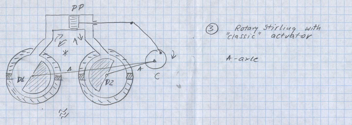
              • I think the dual displacer machine could certainly operate as any stirling engine would on a temperature difference, possibly quite well. I've been pondering some different designs based on your drawing. The exact linkages and such.

                It has stimulated my imagination quite a bit and seems perfectly do-able in vatious ways. I might, if you wouldn't mind, try putting together a small model or two, using empty tin cans rather thsn 55 gallon drums to start with. I'm not very hopeful it could be made "self acting" though as rotary displacers tend to be less efficient generally due to the fact that when 1/2 way around the hot and cold gas or air will mix and rob some power. Also there is no way I can think of to incorporate any kind of regenerator.

                This other machine with the Stirling between the compressor and expander I can only get some general idea of, but should confess, don't quite understand.

                The "Stirling like heat engine" in the middle doesn't look like a Stirling. I'm not really familiar with the workings of a "regenerative heat pump" and can not find any real information about the same so with that one I'm afraid I'm kind of lost, Though it does bear some resemblance to some of my own designs in a way, but only very vaguely. The Stirling driving an air-cycle heat pump in particular, which incorporates an expander and compressor in a "bootstrap" configuration with the Stirling between the hot and cold heat exchangers.

                I think I may have an old drawing up somewhere on another forum.I'll see if I can find something.

                Comment


                • This is also a very rough "concept drawing" that conveys little or nothing as far as the workings of the Stirling, which is shown more or less as a "black box" without any linkage.

                  The turbo-expander is also shown as NOT in a bootstrap here. That is, not on the same shaft as the compressor.

                  At any rate it seems we're thinking along the same or at least similar lines conceptually, even if the drawings are not up to any kind of real enginering standards. LOL.

                  Attached Files
                  Last edited by Tom Booth; 08-31-2016, 01:07 AM.

                  Comment


                  • Something Like This...

                    Hey Tom,

                    I didn't mean to make things difficult to understand. Apparently, a lot of people have been working on ideas like this. Here is a diagram of a twin, rotary displacer Stirling Engine with a twin piston drive by Michael Rosola.


                    In addition to this, all I am suggesting, as you are, is to produce the hot and cold sides using a heat pump cycle of compressing and expanding a working fluid .... preferably air. When the compressor and the expander are placed on the same drive shaft, a large percentage of the mechanical work needed to compress the air is recovered during expansion, thereby reducing the NET work needed to produce the temperature gradient.

                    Michael Rosola also suggests that by using the twin acting piston system, both sides of the machine can be sealed and the air in the displacer/drive piston area can also be raised to a higher pressure than ambient, increasing the pressure differentials on either side of the drive pistons and increasing mechanical energy production for the same amount of heat moving through the engine. Also, by using graphite as the piston material, a good, low friction, self-lubricating seal can be maintained.

                    The web page that discusses Michael Rosola's ideas is here: https://rosola.wordpress.com/home/pr...ling-engine-2/

                    Hope this helps.

                    Peter
                    Last edited by Peter Lindemann; 08-31-2016, 05:41 PM.
                    Peter Lindemann, D.Sc.

                    Open System Thermodynamics Perpetual Motion Reality Electric Motor Secrets
                    Battery Secrets Magnet Secrets Tesla's Radiant Energy Real Rain Making
                    Bedini SG: The Complete Handbook Series Magnetic Energy Secrets

                    Comment


                    • Originally posted by Peter Lindemann View Post
                      Hey Tom,

                      I didn't mean to make things difficult to understand.
                      I'm not sure "difficult to understand" is the right way to put it.

                      I'll readily admit that if I were to hand one of my concept drawings to an engineer he or she would probaly throw me or laugh me out of his or her office.

                      If we are going to try and bridge the gap it may take subjecting these concepts and ideas to some critical analysis.

                      One of my favorite activities is to post this kind of stuff to some physics or engineering forum and ask "why wont this work" or "could this work".

                      Too often I find that my explainations are misunderstood, my drawings miss-interpreted, my theory of operation roundly of flipantly dismissed, or at best, perhaps patiently tollerated, usually tesulting in some impass where someone sites some quote about enthropy or the 2nd law or god forbid I end up stepping on some moderator's ego by trying to explain some point of fact that I have studied in depth, sometimes with my jaw dropping, but checked and doubble checked the facts from dozens of textbooks and professional sources...

                      Just for example, I got into a quite lengthy debate on one physics forum over the function and operation of a turbo-expander.

                      The guy just couldn't get it through my head that a Turbo-Expander is, or must be driven by a motor. He insisted that an expansion turbine is not driven by the expanding gas but rather the turbine, itself driven by a motor, expands the gas. You can't get energy from an expansion turbine he insisted, the expansion turbine takes energy.

                      As you can probably imagine he failed miserably in his efforts to enlighten me due to my stuborn "refusal to learn".

                      I think it is quite amazing that by getting a compressed gas to do work turning a turbine you get energy out of the gas and end up with "free refrigeration" as a byproduct. It does seem "too good to be true" and maybe "there is no free lunch". And of course, on a physics or engineering forum with dozens of trained professionals participating, you would think someone would chime in and say something. Like which one of us had the right idea???

                      Is an expansion turbine driven by expanding gas or does driving an expansion turbine with a motor force the gas passing through the turbine to expand?

                      But, nobody else ever chimed in on that one. No other physicists or engineer steped in to settle the argument. The topic is somewhat obscure so authoratative references are kind of hard to find and drawings and diagrams are open to interpretation...

                      I concluded, for the most part that what I was trying to explain about the expansion turbine was some kind of fairly well guarded "trade secret" of the petrol industry of which even the trained professionals in the field are kept mostly ignorant about, or had I completely lost my mind?

                      An expansion turbine IS damn well driven by the expanding gas. You can so damn well recoup some of the energy used to compress the gas in the process and this does damn straight result in a refrigerating effect, and this does seem rather bizzar and unbelievable when you think about it. BUT A FACT IS A FACT.

                      Unfortunately, I've come to the conclussion that there is no way to get the idea across without building the machine myself and demonstrating that it works, once and for all. But would that really be the end of it?

                      Do you know that the fact that compressed air creates heat was once construed some kind of "witchcraft" when it was demonstrated with some primitive device made out of sticks, probably setting back science and engineering some 200 years? Well is there any hope that a running Self-Acting engine as Tesla described wont cause people to cross themselves and pick up a sledge hammer to smash it or kill the wicked diablo making it turn without any observable physical means?

                      It srems to me you and I may be quite alone in this quest my good friend. We may have a hard road ahead if the intention is to actually build a functional engine. I don't know how much help we can count on.

                      [VIDEO] https://youtu.be/Mvlm-BiCU2k [/VIDEO]

                      https://youtu.be/Mvlm-BiCU2k

                      Apparently, a lot of people have been working on ideas like this. Here is a diagram of a twin, rotary displacer Stirling Engine with a twin piston drive by Michael Rosola.


                      In addition to this, all I am suggesting, as you are, is to produce the hot and cold sides using a heat pump cycle of compressing and expanding a working fluid .... preferably air. When the compressor and the expander are placed on the same drive shaft, a large percentage of the mechanical work needed to compress the air is recovered during expansion, thereby reducing the NET work needed to produce the temperature gradient.

                      Michael Rosola also suggests that by using the twin acting piston system, both sides of the machine can be sealed and the air in the displacer/drive piston area can also be raised to a higher pressure than ambient, increasing the pressure differentials on either side of the drive pistons and increasing mechanical energy production for the same amount of heat moving through the engine. Also, by using graphite as the piston material, a good, low friction, self-lubricating seal can be maintained.

                      The web page that discusses Michael Rosola's ideas is here: https://rosola.wordpress.com/home/pr...ling-engine-2/

                      Hope this helps.

                      Peter
                      Last edited by Tom Booth; 09-01-2016, 06:00 AM.

                      Comment


                      • Tom,

                        Have you considered a Tesla Turbine? It has been proven to be one of the most efficient designs. It is also much simpler to build. Anyone with reasonable machining skills and a lathe and milling machine can build one.

                        It can be used as an expansion turbine or a compressor/pump. With some fairly simple modifications it can even be used as a fuel driven turbine.

                        Carroll
                        Just because someone disagrees with you does NOT make them your enemy. We can disagree without attacking someone.

                        Comment


                        • Do Not Dispare, my friend...

                          Tom,

                          I am not concerned about whether other people believe this will work or not. Working models of new devices have never needed ignorant people to believe in them to work! I also have no expectation that there will be an immediate commercial market for these machines. That is also irrelevant! I am reminded of the fact that Archimedes invented the rotary screw pump in 600 BC to easily pump water out of the bottom of leaking boats. It took another 2,300 years before anybody else figured out that a thin slice of that very same screw could be used to actually PUSH a boat through the water! DUH! Today, we call it a propeller. To say that we belong to a group of people who really aren't that smart is an understatement!!!

                          Now, back to real science. There is no such thing as the "heat of compression." This idea was the brain child of James Joule and was part of his "proof" that mechanical energy could be converted into heat. He studied and published on at least 4 different methods to illustrate this process. They included: 1) running electricity through a resistor and measuring the temperature rise, 2) turning a paddle wheel in a tub of water and measuring the temperature rise, 3) pushing water through a conical sieve and measuring the temperature rise, and finally, 4) compressing a gas and measuring the temperature rise. The first three examples dissipate the initiating source energy to produce the temperature rise, but the fourth example does not!

                          Tesla did not believe in the "Laws of Thermodynamics".... end of story!! He openly published on the idea that electricity behaved more like a "gas under pressure" than anything else, and that electricity followed fluid dynamic laws much more closely than thermodynamic laws. Before the Kinetic Theory of heat became prominent, heat was considered similarly. Carnot, who believed in Caloric Theory, developed all of the math to build heat engines based on the idea that heat was a subtle fluid. This is also, absolutely, what I believe.

                          A volume of air is actually a volume of two fluids. One is the air and the other is its content of heat. Boyle's Gas Laws say that if I confine that volume of gas and mechanically force it into a volume half its size, both the pressure and the temperature will rise. This does not mean there is more HEAT in the system. It simply recognizes that both fluids were densified.

                          The external, mechanical pressure applied to the gas is expressed as a rise in the pressure of the gas itself. This does NOT represent an "energy conversion." Pressure was added to the gas and it exhibits more pressure within itself. The heat content of the gas is now also forced to express itself within half its original volume. This is the temperature rise! But this represents the densification of the heat that was already in the gas, NOT the production of "new heat" by the action of pressurizing the gas. Arguments like this were originally raised against Joule's thesis, but were eventually ignored as the proponents of Kinetic Theory pushed Joule's work forward as "proof" that Caloric Theory was bogus. But as you can see, it did not make this reality go away!

                          This is why you can compress a gas, remove some of its heat, decompress the gas and recover some (most) of its stored mechanical energy, and end up with refrigeration effects "seemingly" for free. People who fail to understand this are never going to comprehend WHY these machines can do what they do!! Everybody who has looked at this closely agrees that the "magic window" for highest benefits is moving back and forth between about 1 Bar and 2 Bars of pressure. The temperature swing is well over 250F and the pressure drop on the high side, after significant heat is removed, is still only about 0.5 psi. These are facts that can be harnessed to drive these machines!

                          Citfta,

                          The Tesla Turbine is an amazing machine. There is little doubt of that. But they are only efficient at very high speeds, usually above 10k rpm. In contrast to that, scroll compressors are a "positive displacement" compressor with a very high efficiency at almost any speed. For the kind of machine we are contemplating, I believe that the scroll compressor should be investigated first. Small scroll compressors with low compression ratios are available "off-the-shelf" and run well in reverse as expanders. Here is one example. https://airsquared.com/products/scro...2h020a-bldc-c/

                          Best regards,
                          Peter
                          Last edited by Peter Lindemann; 09-01-2016, 11:59 PM.
                          Peter Lindemann, D.Sc.

                          Open System Thermodynamics Perpetual Motion Reality Electric Motor Secrets
                          Battery Secrets Magnet Secrets Tesla's Radiant Energy Real Rain Making
                          Bedini SG: The Complete Handbook Series Magnetic Energy Secrets

                          Comment


                          • Peter
                            Do you mean one or two bars variation at any PSI or is that one or two bars variation above atmospheric pressure?
                            Is there a specific pressure at which to Bar variation is the most effective?
                            Thanks.
                            William Reed

                            Comment


                            • Peter
                              I hope I am not off track hare but wouldn't a double ended solenoid compressor Work well in this scenario?
                              William Reed

                              Comment


                              • Reversability is the Key...

                                Originally posted by rosehillworks View Post
                                Peter
                                I hope I am not off track hare but wouldn't a double ended solenoid compressor Work well in this scenario?
                                William,

                                In general, the best window is between 1 Bar and 2 Bars, meaning between One Atmosphere (14.5 psi) and Two Atmospheres (29 psi).

                                The Key to this working is the ability to recover the mechanical energy needed to compress the gas. Tesla says in the article about the Self-acting Engine that he believed that his Mechanical Oscillator would work. The Mechanical Oscillator is essentially an AIR SPRING connected to a piston operated by compressed air. Tesla knew that his "air spring" was also a "thermal spring". The idea of an air compressor on the same shaft as an air expander with heat exchangers in-between is nothing more than an "air spring" with a delay in the two phases and a few higher losses from friction. Both ideas create similar effects, being a temperature gradient and the conservation of mechanical energy.

                                Thinking this all through again makes me believe that if we could convey the temperature swings generated in the air spring away quickly enough to an external air chamber, we might be able to operate a double sided expansion piston from the pressure changes. In this case, a Stirling type of engine could be produced where an "air spring" would replace both the displacer AND the hot and cold sources that power a double acting piston that moves back and forth from the pressure changes.

                                Maybe Tesla actually solved it and didn't tell anyone!!

                                Food for thought!!!

                                Peter
                                Last edited by Peter Lindemann; 09-01-2016, 11:40 PM.
                                Peter Lindemann, D.Sc.

                                Open System Thermodynamics Perpetual Motion Reality Electric Motor Secrets
                                Battery Secrets Magnet Secrets Tesla's Radiant Energy Real Rain Making
                                Bedini SG: The Complete Handbook Series Magnetic Energy Secrets

                                Comment

                                Working...
                                X