Announcement

Collapse
No announcement yet.

Beating lenz's law

Collapse
X
 
  • Filter
  • Time
  • Show
Clear All
new posts

  • #91
    hello

    thank you very much Gyula

    one more thing , what size of wire sould i use ? 0,45 is ok ?

    i also have some 0,15

    thank you
    wojsciech

    Comment


    • #92
      help with transformer

      wojwrobel, it is really necessary for the input current to be AC? will you take the input from the grid?

      guys, maybe someone can help me with this... i have a one to one transformer, primary and secondary with same turns, im lightning a led super bright in the secondary, but when i read voltage across the load (led), it only reads 0.01V, the led needs at least 2.5V, someone can guess? im using a digital multimeter!

      hugs

      Comment


      • #93
        Originally posted by juju View Post
        wojwrobel, it is really necessary for the input current to be AC? will you take the input from the grid?

        guys, maybe someone can help me with this... i have a one to one transformer, primary and secondary with same turns, im lightning a led super bright in the secondary, but when i read voltage across the load (led), it only reads 0.01V, the led needs at least 2.5V, someone can guess? im using a digital multimeter!

        hugs
        Your DMM might only recognize sinusoid AC (and at 50/60 Hz only), an oscilloscope is always more accurate for such a measurement.

        Comment


        • #94
          thanks

          i dont have an oscilloscope!

          do you know some pulse circuit to send 50/60 Hz only so i can assure that its possible to read the voltage on my secondary?

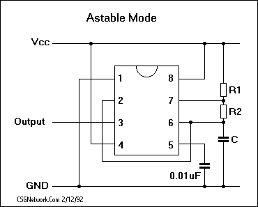
          im using a standard led 555 timer pulser, but i dont know how to calculate the frequency im sending!

          hugs

          Last edited by juju; 05-16-2010, 06:36 PM.

          Comment


          • #95
            Well technically you are generating pulsed DC, so your DMM won´t be able to read that. With a sine wave it would work.
            You can calculate the 555 frequency for example here : Astable 555 Square Wave Calculator

            Comment


            • #96


              thank you,

              what is corious is that i can read the amp draw at the secondary, but not the voltage!

              king regards

              Comment


              • #97
                Originally posted by wojwrobel View Post
                hello

                thank you very much Gyula

                one more thing , what size of wire sould i use ? 0,45 is ok ?

                i also have some 0,15

                thank you
                wojsciech
                Hi, it would be better to use 0.45mm to reduce copper loss wrt the 0.15

                Comment


                • #98
                  help

                  my voltage reading on the secondary still is 0.01V... but i can read amp draw and light a led!

                  i should have 56.8Mhz with my calculated values:

                  Farads 0.0001 (100uf)
                  Resistor 1 - 98 ohm
                  Resistor 2 - 78 ohm

                  the capacitor from the 5 pin to the negative is a 100nF...

                  Duty Cycle Percentage - 69.291
                  Frequency In Hertz - 56.811
                  Seconds Low - 0.005
                  Seconds High - 0.012

                  this is not sine wave?


                  hugs

                  Comment


                  • #99
                    hello

                    guys i have a question how to calculate the core diemension vs magnet size?

                    let say i have magnet 29mm diameter, 10mm thick so what size of core would be the best for this magnet? is there any table or formula? for best performance?

                    also another thing is how to extract the most of power from coil ? i mean what is better more turns with thin wire or les turns of thicker wire? lest say we dont have Lenz effect so what setup would be best ??

                    and one more thing i did some more research by just playing with magnets and toroid and find a way to get even more power by simply putting magnet N and S side by side , its creates twices more power than one magnet
                    its just like magnet flux goes thru toroid from N to S and vice versa just like in picture , thouse 2 coil gave me 5v and 110ma thru one magnet pass thats 0,55W i think thats a lot coil 1 28ohm and coil 2 is 19ohm 0,45wire
                    now imagine you have 40 magnetys on rotor so 1rps gives you 40x0,55=22W per 1core and you have 40 cores thats 880W/1rps


                    cheers
                    wojsciech
                    Last edited by wojwrobel; 05-18-2010, 01:27 PM.

                    Comment


                    • Originally posted by wojwrobel View Post
                      hello

                      guys i have a question how to calculate the core diemension vs magnet size?

                      let say i have magnet 29mm diameter, 10mm thick so what size of core would be the best for this magnet? is there any table or formula? for best performance?

                      also another thing is how to extract the most of power from coil ? i mean what is better more turns with thin wire or les turns of thicker wire? lest say we dont have Lenz effect so what setup would be best ??

                      cheers
                      wojsciech
                      do you know the pound force of your magnets?

                      more turns with thin wire will give you more volts and less amps, less turns of thicker wire will give you less volts and more amps! depend on what you want!

                      you should use the same size in coil 1 and coil 2 you can connect them in series and they will be completely in phase one onether! as you have an S-N alternator you should connect the end of the first coil, to the end of the second coil (or wound them reversed and connect end first and beggining second), so 28 ohm + 19 ohm = 47 ohm / 2 = 23,5ohm each coil!

                      in this topic you have the formulas that harvey gave:

                      http://www.energeticforum.com/renewa...volt-coil.html

                      how is doing your bi-filar toroid replic?

                      hugs
                      Last edited by juju; 05-18-2010, 04:46 PM.

                      Comment


                      • hello

                        the bi-toroid i have a little problem i have to studdy more about , turns thicknes and resistance of wire in transformers

                        i also changed the setup because i took closer look to Heins video and the coil is little different..
                        it sould look like this


                        and winding this coils ..... is crazy.

                        cheers
                        wojsciech

                        Comment


                        • help?

                          guys anyone can help me?

                          how do i send sine wave in my 555 timer? i calculated the frequency to 56.8hz on my primary, but i cannot read voltage across my secondary.. my digital multimeter should be able to measure 50-60Hz sinewave but shows 0.0.1V but im lighting a led, someone can take my doubt?

                          please!

                          hugs

                          Originally posted by juju View Post
                          my voltage reading on the secondary still is 0.01V... but i can read amp draw and light a led!

                          i should have 56.8Mhz with my calculated values:

                          Farads 0.0001 (100uf)
                          Resistor 1 - 98 ohm
                          Resistor 2 - 78 ohm

                          the capacitor from the 5 pin to the negative is a 100nF...

                          Duty Cycle Percentage - 69.291
                          Frequency In Hertz - 56.811
                          Seconds Low - 0.005
                          Seconds High - 0.012

                          this is not sine wave?


                          hugs

                          Comment


                          • wojsciech

                            how r you planning to send 12V AC 60Hz true your primary?, and how will you put voltage and amperage out of phase with each other to the power factor to be 0?

                            hug

                            Comment


                            • Originally posted by juju View Post
                              guys anyone can help me?

                              how do i send sine wave in my 555 timer? i calculated the frequency to 56.8hz on my primary, but i cannot read voltage across my secondary.. my digital multimeter should be able to measure 50-60Hz sinewave but shows 0.0.1V but im lighting a led, someone can take my doubt?

                              please!

                              hugs
                              Hi,

                              Unfortunately the 555 timer is not designed for sine wave output. Here you can see typical waveforms at its differet pins:

                              555 Oscillator (Astable Multivibrator)

                              The only rescue for you would be an oscilloscope... unfortunately.

                              Gyula

                              Comment


                              • Sine wave creation is possible with other kinds of ICs or PICs or wein bridges, but you would need output buffers to reach a significant output current,
                                which is not an easy task if you are not advanced in electronics.
                                The 555 has a quite high output current, compared to other ICs. Thats why people like to use it (for square wave purposes).

                                Comment

                                Working...
                                X