Announcement

Collapse
No announcement yet.

Avramenko's plug - Single wire power

Collapse
X
 
  • Filter
  • Time
  • Show
Clear All
new posts

  • #46
    Originally posted by stephenafreter View Post
    @amigo:
    please can you tell me which one of the 16 models you recommend among the ONsemi ?

    ON Semiconductor MPSA06: Small Signal General Purpose NPN

    They ship only at minimum 2,000 units if I understood well ?
    2,000 x 0.064 = 128 USD minimum, yes ?

    Thanks for sharing,
    MDG
    Uhm, why go to the manufacturer, they won't sell you any low quantity and will charge a premium as well.

    I just got a package today from NewArk.com of 500 MPSA06 ON Semi. I paid cents for each one, they have a promo price right now of 4.5c/each for 500+ quantity.

    http://www.newark.com/on-semiconduct...questid=313578

    Just look for BULK designation, since tape/reel is generally larger volumes.

    Even if you buy 100 it's just $5 total - shipping will probably cost you more.

    I tested one right away and it worked, so they are a good batch, at least what I got (604 production date - 2006/04th week).

    If you don't like NewArk.com you can go to Digi-Key.com or Mouser.com, they all carry them.
    Are the ravings of a lunatic signs of a genius?

    Comment


    • #47
      Finally had success with lighting a 4w flouro tube. Not quite like how you have it in your circuit.

      I'm still trying to tune this thing just right, plus I need to modify the circuit a little. I still need to add the diode from + to L1, and my L3 coil doesn't quite look like yours but it is 34uH. Using 26 guage wire on a slightly larger form.

      One thing I thought was pretty neat is you can see the high voltage build if you hold an end of the tube and slide it up and down the coil (L3). It reminds me of a video gotoluc made a while back about resonance.

      As for the MPSA06s I have I *think* they are Fairchild. I got them from Jameco.

      Jameco Electronics ICs & Semiconductors: VARIOUS: MPSA06

      Comment


      • #48
        spent some more time measuring and adjusting the coils. Have some decent light output with minimal amp draw.

        Running around 17 volts, 53 milliamps.

        large air coil measures 24uH, Small axial 8uH and the tuning coil is just a coil wrapped loosely around a small ferite core adjustable from 1-7uh.

        I bought some of those adjustable slug tuned cores but its hard to use them on a breadboard without actually gluing them. The cores are really fragile and don't want to ruin my supply till I get this mounted on a PCB.

        @ amigo, where did you get those PCB pins sockets for swapping components?

        http://i197.photobucket.com/albums/a...oo/SEC15-3.jpg

        Comment


        • #49
          @Mutten,

          Excellent !

          Yeah, those Fairchild MPSAs are the same ones I also ordered, but they have not arrived yet (takes time from Texas/US to Ontario/CAN).

          I have been playing with various coil configurations and really you can use any approximate coil as long as your LC tanks are tuned. The 8uH I had used 10 even 20uH. the 24uH...I used 40uH...get various effects, but the full replication only happened when using the "right" transistors (ON or Fairchild).

          My cores with the slug are pretty cool because the pin spacing matches the breadboard so I just slide it in.

          I recall Dr. Stiffler talking about parasitic capacities involved in the circuit, and so breadboard version might not be the best way of doing things. I had two different kinds of breadboards and until I replaced the one that was giving me headaches (beige colour) with the one that worked right away (white) I was getting nowhere.

          The sockets are ordinary Single Row Pin Sockets, as sold in my local electronics store, chopped into single pins.

          Looks something like this, just shorter pins: http://img.alibaba.com/photo/2076161...double_row.jpg
          Are the ravings of a lunatic signs of a genius?

          Comment


          • #50
            AV Plug??

            Originally posted by Mutten View Post
            Dr Stiffler uses the AV plug in his circuits.

            His website seems to be down, but his youtube page is still up

            YouTube - MRH2O2's Channel

            post on the OU message board with a circuit diagram.

            Selfrunning cold electricity circuit from Dr.Stiffler


            I'm currently putting together one of his simple SEC boards. Got my order in from Jameco.

            I'm looking at this AV plug circuit and I see two diodes connected as a half wave rectifier. That's a standard electronic circuit.

            This concept of pulling current out of the air has been around for over a hundred years. The crystal radios did exactly the same thing, long ago. One crystal radio design uses the current from the antenna to power the transistor that amplifies the audio signal, to drive the earphone.

            The coils and capacitive hats are how antennas are modified to make a long antenna shorter, for a given frequency. I saw some ad for a little blue LED stickum that comes on when your cell phone is working. It's next to the antenna and steals some power from it when it's sending a signal.

            WOW! I've got a cell phone that's generating power from the Aether!

            Comment


            • #51
              Originally posted by amigo View Post
              Uhm, why go to the manufacturer, they won't sell you any low quantity and will charge a premium as well.

              I just got a package today from NewArk.com of 500 MPSA06 ON Semi. I paid cents for each one, they have a promo price right now of 4.5c/each for 500+ quantity.

              ON SEMICONDUCTOR|MPSA06G|Bipolar Transistor | Newark.com

              Just look for BULK designation, since tape/reel is generally larger volumes.

              Even if you buy 100 it's just $5 total - shipping will probably cost you more.

              I tested one right away and it worked, so they are a good batch, at least what I got (604 production date - 2006/04th week).

              If you don't like NewArk.com you can go to Digi-Key.com or Mouser.com, they all carry them.
              I checked the link above and they're sold out, with a lead time of about 6 months. :-(

              Mouser says "On Order" which means they're out pf stock.

              One guy on eBay sells 25 pcs for $7.88, including USPS shipping which is probably the quickest. It's expensive on a per transistor basis but overall it's cheaper if all you are going to use is 25 in the next year or so.

              I'm not sure why this particular transistor is being chosen. There are other molre common substitutes, in fact there are better choices. One is the BD139, which can handlle more power and current, and is not much more, only about 25 cents apiece.

              Comment


              • #52
                Originally posted by amigo View Post
                @Mutten,

                Excellent !

                Yeah, those Fairchild MPSAs are the same ones I also ordered, but they have not arrived yet (takes time from Texas/US to Ontario/CAN).

                I have been playing with various coil configurations and really you can use any approximate coil as long as your LC tanks are tuned. The 8uH I had used 10 even 20uH. the 24uH...I used 40uH...get various effects, but the full replication only happened when using the "right" transistors (ON or Fairchild).

                My cores with the slug are pretty cool because the pin spacing matches the breadboard so I just slide it in.

                I recall Dr. Stiffler talking about parasitic capacities involved in the circuit, and so breadboard version might not be the best way of doing things. I had two different kinds of breadboards and until I replaced the one that was giving me headaches (beige colour) with the one that worked right away (white) I was getting nowhere.

                The sockets are ordinary Single Row Pin Sockets, as sold in my local electronics store, chopped into single pins.

                Looks something like this, just shorter pins: http://img.alibaba.com/photo/2076161...double_row.jpg
                In the limited reading I've done on this, I have yet to see a frequency given, or anything to do with the amount of power the transistor can put out. When building circuits that handle RF it is mandatory that the parasitic inductances and capacitances be minimized, in order to prevent spurious oscillations. And the proto boards have high stray capacitances and inductances because of all the long leads and sockets. So it's not a good way to build a RF circuit. But then it's possible that the circuit works better with spurious emissions, after all, the more RF you radiate, the more power you can pick up, right?

                Good to see the updates on your experiments.

                Comment


                • #53
                  Originally posted by Watson View Post
                  I checked the link above and they're sold out, with a lead time of about 6 months. :-(

                  Mouser says "On Order" which means they're out pf stock.

                  One guy on eBay sells 25 pcs for $7.88, including USPS shipping which is probably the quickest. It's expensive on a per transistor basis but overall it's cheaper if all you are going to use is 25 in the next year or so.

                  I'm not sure why this particular transistor is being chosen. There are other molre common substitutes, in fact there are better choices. One is the BD139, which can handlle more power and current, and is not much more, only about 25 cents apiece.
                  Hi Watson,

                  You pulled this thread out of the past...

                  Regarding the choice of the transistor, both Doc Stiffler and many of us have tried different models and makers and yes some other do work, but the best results are achieved with ON Semi MPSA06.

                  It appears that there's something in the manufacturing process of that specific transistor, and only from ON Semi, that gives the unusual effects observed.
                  Are the ravings of a lunatic signs of a genius?

                  Comment


                  • #54
                    Originally posted by Watson View Post
                    I'm looking at this AV plug circuit and I see two diodes connected as a half wave rectifier. That's a standard electronic circuit.
                    Here is an improvement:
                    THE PASSIVE MICRO - INDUCTIVE ARRAY AS A NOVEL ENERGY CONVERSION SYSTEM
                    by Nicholas A. Reiter and Dr.Samuel P. Faile, 10 January 1996

                    Comment


                    • #55
                      Problem understanding Avramenko circuit

                      I have seen this circuit that I'm building:


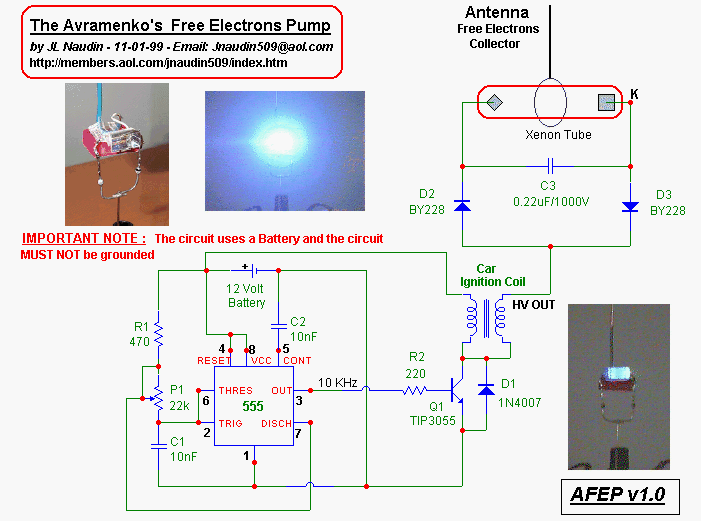
                      I don't fully understand how to connect the wires to the ignition coil.
                      The coil has 3 connections:
                      • +12 VDC
                      • -12VDC
                      • High voltage


                      In the schematics the wire of the left/up side is connected to the positive to the battery, I assume that connection is the +12VDC. In the left/down there are connected the TIP3055 (I assume that part is the -12VDC). And the diode 1N4007 is connected at the same time to the -12VDC and the coil of the high voltage wire?

                      I attach this picture that I made to know if my interpretation is correct or not


                      Uploaded with ImageShack.us

                      Comment


                      • #56
                        Your interpretation is correct, though there's no -12VDC, just 0V.

                        The design of the ignition coil is such that one of the poles of the secondary winding is connected to the primary, just like in the original schematics above, effectively making a 1/4 wave secondary so that the top pole of the secondary has the maximum voltage output (node being at the bottom where the primary and secondary interconnect).
                        Are the ravings of a lunatic signs of a genius?

                        Comment


                        • #57
                          Is the output only to light the xenon bulb? Can the free electrons be extracted to do work? Very interesting!

                          I wonder if the xenon bulb could be replaced by a vacuum tube in order to harness the energy?

                          Comment


                          • #58
                            Originally posted by amigo View Post
                            Your interpretation is correct, though there's no -12VDC, just 0V.

                            The design of the ignition coil is such that one of the poles of the secondary winding is connected to the primary, just like in the original schematics above, effectively making a 1/4 wave secondary so that the top pole of the secondary has the maximum voltage output (node being at the bottom where the primary and secondary interconnect).
                            thanks amigo,
                            I have tested the avramenko plug and it's curious. I forgot that I had a pulse DC generator at home. It's a PWM fixed at 30Khz. So I tested the AV plug using a 1kV 0.2 uF capacitor. The first thing I noted is that the single-wire transmision cable you cannot get shock.
                            The second is that I can charge the cap and when you short you don't get a shock when you're touching the metallic plate that you use to short the cap.
                            Is this usual?


                            Originally posted by jtanguay View Post
                            Is the output only to light the xenon bulb? Can the free electrons be extracted to do work? Very interesting!

                            I wonder if the xenon bulb could be replaced by a vacuum tube in order to harness the energy?
                            I have tried other "rectification" circuit to transform the unidirectional energy and It works too. But it takes more time to charge a simple 50 Volt electrolytic capacitor. But with that rectification (the second one) I can get polarized energy (one wire positive and other wire negative).

                            2 questions that nobody in a well-known electronic forum cannot answer...
                            1) The energy in the single-line is pure voltage (radiant energy)?
                            2) Can I amplify this voltage energy? If true, how?

                            Comment


                            • #59
                              Imhotep relay

                              Originally posted by AetherScientist View Post
                              I have seen this circuit that I'm building:
                              You can replace the entire 555 circuit with a simple relay - Imhotep's
                              bare bones single relay method. Works great. Unless you want it variable.
                              Sincerely,
                              Aaron Murakami

                              Books & Videos https://emediapress.com
                              Conference http://energyscienceconference.com
                              RPX & MWO http://vril.io

                              Comment


                              • #60
                                Originally posted by Aaron View Post
                                You can replace the entire 555 circuit with a simple relay - Imhotep's
                                bare bones single relay method. Works great. Unless you want it variable.
                                but can I send energy using only 1 wire with imhotep's circuit? I think no, but I would like to see you answer. Another similar circuit that I have heard about is the Brovin-Kacher.

                                Comment

                                Working...
                                X