Announcement

Collapse
No announcement yet.

High Voltage from Thin Air?

Collapse
X
 
  • Filter
  • Time
  • Show
Clear All
new posts

  • @samedsoft,

    last time I checked you were NOT the moderator so please do not misrepresent one.


    @Dr.Stiffler and gmeast

    WTF is wrong with you two? (if you don't know WTF means, check Urban Dictionary: wtf as well)

    Have you seen that movie "Grumpy old men"? That's how I picture you two, Jack Lemmon and Walter Matthau getting at each other's throat?

    I sense this must be something to do with the age, since you both appear to be older than most of us here. Sorry I have given you credit to have more wisdom than the rest of us due to the age - I guess I made a principal mistake.

    Either that or you both have some mineral/vitamin deficiency which is affecting your cognitive functions, but I'm not your physician and can't help you there.

    NOBODY is out here to get YOU. Matter a fact this forum is so much devoid of OU.com kind of non-sense and is filled with some really kind, good and friendly people overall (at least from my personal experience).

    I'll answer the damn questions:

    Yes, you need a Spectrum Analyzer if you wish to see the spectra of your oscillations. As SEC is a Ultra Wide Band circuit it will oscillate from 1 all the way up to 500 MHz.

    Yes, you need a good LCR meter with a good range and precision, down to micro or nano henries.

    Yes, anyone serious about electronics should have at least one true RMS meter. Any meter would have a transistor gain capability among other things.

    Yes, having an oscilloscope is mandatory these days in any environment and for $50 you get a decent one on eBay.

    Yes, a bench power supply is mandatory whether or not you deal with SEC.

    Yes, a signal generator is necessary when dealing with non-standard AC/DC circuits ie. pulsed/impulse, etc.

    ANYONE serious about electronics (amateur or professional) would have at least a bench supply, a true RMS meter, a soldering iron, bunch of components, wire.

    Only your budget is the limit. Asking what exactly you need to buy for a single project only works in the Military where money is not the issue, not in the civilian home environments.
    Are the ravings of a lunatic signs of a genius?

    Comment


    • @Freezer

      I don't mean to say that the waves are identical in any manner. I am just saying that they are VERY similar in character...or effect. The actual waves are different in appearance obviously due to the lack of much of the iron in the SEC (except for the tuning ferrite). All I am saying is there are many ways to do the same thing, and, if people weren't worried about personal credit, profit, novelty, etc...then we would be more inclined to see how things are the same, rather then how they are different.


      If you look at the two circuits they are almost identical, but, you would have to realize that the input of the SEC with all the inductors and capacitors mimics the characteristics of the Tesla coil feedback coil. But, as you said, you are no expert...so I will not explain to you how the CAPACITIVE COUPLING of the Tesla coil primary and feedback coil is the same as the SEC's network of caps and inductors DIRECTLY COUPLED to the gate!

      Anyway, you don't have to worry about offending me...I'm used to people not understanding what I am trying to say, and to tell you the truth...it's never worth wasting one's breathe to try and explain something to someone who is uninterested in hearing it
      Last edited by Radiant_Science; 05-05-2009, 03:00 AM.

      Comment


      • Maybe this is the right operation mode

        Gentlemen please

        Where I come from we have a saying: If you don't have anything good to say, say nothing.
        No offense at anyone.

        What I would like to see here is focus on what brought a group of people together: The fantastic discoveries of Dr. Stiffler.

        Everyone are free to start a new thread discussing similarities between technologies or what inventory to buy for a good workshop.
        Again no offense intended.

        In my humble opinion Doc has technological skills way beyond what most of us can dream of, and he is willing to share this with the rest of us.

        So the least we can do in return, is to follow the terms of this thread as seen from history, after all this is Doc's thread.

        I also feel this is my thread in a way, as I have put hard work in it already,
        I have nearly used all my awake time since I started, I have even dreamed about it.

        Although I will not call this an easy win to work on, this is what I personally presently consider the most promising
        electrical technology giving bang for the buck ! And we even have the privilege of being able to communicate with the inventor.

        ----------------

        Is this the right mode Doc ?

        Nobody has promised life is easy, and even though I got directions I honestly did not know what to do with it.

        My first thought was to have the same phase at both ends of the S-Gate, but I could see no way how to achieve that.

        As I'm not an easy quitter I started experimenting to find some pattern in this. At a point operating at 10,3MHz suddenly
        the Ug11 changed waveform. As a bonus the signals was now close to being in phase as I thought of initially.

        Having this result I quickly took photos of it, as I have earlier left a setup and had to use time to get back.
        I know this is not perfectly tuned, as the values are not matched like they should be if I'm right on this.

        But now I have the setup I want to report it before going further on.

        If this is the right mode of operation, it looks like L2 = L22, L33 = 2 * L22. I can't say for sure,
        but it looks like being right to me. At least my poor Weller soldering station goes crazy again.

        And let me confess I do not have a frequency analyser in my shop, as I have lived happily without such a thing working with
        SW and digital HW. But I have a HP logic analyzer.

        Now I want the frequency analyzer in my shop, my budget is limited because of the financial crisis,
        but it has not put me down. Maybe I should start a new thread on what could be a good bargain.

        So please bear with me presenting my results with ordinary scope shots, thats what I have, note Ug22 and Ug11 being in phase almost,
        and the broadband HF on the center of the inner tube.
        The lower trace is on the outer lef tube connected to the exciter, the upper strace the other right tube.

        The last picture the upper trace is from the middle of the inner tube, note the RF frequencies.

        My two 1000:1 HV probes come in handy, because they have a lower capacitance 3pF opposed to the ordinary probes 11.5pF.

        I guess the consumption will drop when L2 = L22 perfectly. Light is very nice but not blinding.


        I have one additional tip on measuring the current consumption.

        Having a capacitor > 1000uF knowing the exact value, the average current can quite precisely be measured with the cap and a watch
        using the definition that Amps = Volts * Farads / seconds.

        Know the starting voltage, remove the meter, remove the power and measure the voltage after an amount of time,
        eg. I measured 4V in 20 seconds over 2200uF giving approx. 450uA.

        When the consumption is so low the cap can operate the circuit for some time, measure the voltage drop in a given time,
        and the average current can be calculated.

        After all that is the purpose of a cap in an integrator.

        Eric
        Attached Files
        Last edited by Tecstatic; 11-03-2009, 12:37 AM.

        Comment


        • In line with our recent resolution to proceeed with something more practical ie. light production, or in other words "No more Mr. Nice Guy" ... here is my first test using a high lumens LED (20W pure white 1000 lumens LED, 13-15V, 1,400-1,800mA, off of eBay).

          First photo is of the actual 20W LED.

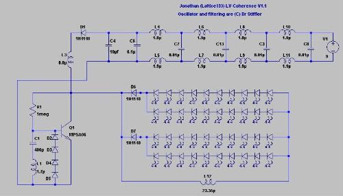
          Second photo is the LED lit using Latice333's backward diodes circuit - no AV plug, single line/diode and 10V from the PSU.

          Third photo is the LED lit directly through the PSU DC 13V. This little bugger is very bright though you can't really see that from the photo, but with two of these I could light up the room big time. The LED is sitting on a CPU heat sink as it gets pretty hot (it pushes almost 2 amps through this little thing )

          NEVER EVER EVER...EVER...NEVER...DIRECTLY LOOK AT A LED, ESPECIALLY ONE OF THESE, EVER.


          The SEC light is obviously lacking in power, but this is just a start...

          P.S. Now that I think of it, I should've bought two of these so I could compare the illuminations and the working temperatures...
          Last edited by amigo; 05-06-2009, 12:47 AM. Reason: more thoughts...
          Are the ravings of a lunatic signs of a genius?

          Comment


          • adjuatable coil Lb

            where to get adjustable coil for LB ... nice one like on the board ... what ranges are standard? Catalogs have narrow range & nothing like on his boards I can find. AND 3mm or 5mm LEDS?
            Last edited by gmeast; 05-06-2009, 01:41 AM.

            Comment


            • EVERY one here has some thing to contribute, so lets not turn this forum into OU.com, thanks, i am glad Greg is back.

              Ash

              Comment


              • Originally posted by Freezer
                Awesome amigo.

                Those leds are from the dealsextreme site. They sell 10w, 20w, and 50w single emitters there. I have to pick some of the up when I get the money.

                DealExtreme: Electronics DIY Parts (Page 4)
                Thanks

                Mine were from eBay, Hong Kong supplier, cheaper as well: 1PC High Quality 20W White 1000 Lumen Save Power LED - eBay (item 400047157947 end time May-06-09 07:30:25 PDT)


                This might work, but I've never bought any of these.
                Adjustable Slug Tuned Coil (Pkg of 4)-The Electronic Goldmine
                I got couple of these, they are much smaller (in size) than they appear in the photo, and as such I do not find them as useful. Did not bother to check the impedance or to rewind them to suit the purpose yet...
                Are the ravings of a lunatic signs of a genius?

                Comment


                • Originally posted by gmeast View Post
                  where to get adjustable coil for LB ... nice one like on the board ... what ranges are standard? Catalogs have narrow range & nothing like on his boards I can find. AND 3mm or 5mm LEDS?
                  At least for me, an electronics surplus store in the city has a whole lot of them. I doubt they'll ever run out as it seems I'm the only one buying these, lol.

                  Chokes and Coils


                  LEDs:

                  eBay Store - Light of Victory Led Store-lvehk: NEW LED PRODUCTS, 5mm 10mm MultiColour Flash LED

                  eBay Store - LED: Super Bright, Flashlight, bulb
                  Last edited by amigo; 05-06-2009, 03:25 AM.
                  Are the ravings of a lunatic signs of a genius?

                  Comment


                  • Dr. Stiffler,

                    thanks a lot for the parts list! I appreciate it very much!

                    ABC

                    Comment


                    • @gmeast

                      If you are eager to get going, you can probably get a small ferrite rod from an old power supply. Mine is 5mm diameter x 20 mm long. There is some lacquer remains so it acts like a thread in my 14 turn 0,63 mm wire coil wound around the rod making it nicely adjustable.

                      But when we get to some fixed final application, I guess its best to convert to an air coil.

                      Eric

                      Comment


                      • Dear Doc

                        I just want to thank you for your list of dates for publishing your research on

                        www.stifflerscientific.com

                        Count me in for buying

                        Eric

                        Comment


                        • Amigo
                          I guess we're practically neighbours. I spend hours in the A1 Electronic surplus store there at the Queensway. Yes they have a great selection of chokes but they are mostly unmarked and an LC meter is a must.
                          I'm sure you are aware of this store "SAYAL Electronics" at Matheson and Dixie road Mississauga- They have an excellent selection of everything you can think of especially transistors at very good prices --MPSA06 's at $1.00 Can. for a pack of six.
                          All
                          Another point of interest, especially to the newbies that are working on the SEC-15 --Make sure you put your new/spare transistors in a metal container away from the project as I have had a countless number of transistors still in their packages zapped from the RF/HV spikes when I had them laying around near by the project.

                          Comment


                          • Zap

                            Originally posted by Parav View Post
                            Amigo
                            .................................
                            All
                            Another point of interest, especially to the newbies that are working on the SEC-15 --Make sure you put your new/spare transistors in a metal container away from the project as I have had a countless number of transistors still in their packages zapped from the RF/HV spikes when I had them laying around near by the project.
                            Thanks for the alert.

                            Comment


                            • @gmeast,

                              I am so sorry for my rudenes.. Please forgive me if I broke your heart.

                              @ALL

                              I have attached my proposed Triple Spatial Gate to this community to comment on.

                              @Lidmotor & Amigo

                              On the s-gate, do you think more gates means more capture?

                              Please forgive me all!

                              Yours Nuri!
                              Last edited by samedsoft; 05-07-2009, 04:34 AM.

                              Comment


                              • Please respect the authors published material.

                                @samedsoft

                                I have a comment.

                                I have no idea if a multiple capacitor excited linear wave conductor can be a gain, maybe, maybe not.

                                I do not feel on safe ground with Doc's SGate, I need to understand the operation of the SGate before I can even think of an extended functionality.

                                But if you make a proposal, please make your own drawing.

                                Here you have made copy-paste on Dr.Stifflers original drawing. If this drawing is viewed out of this context, then it appears as if it is made by Doc, and that is not right or fair IMHO.

                                @ALL
                                If anybody has an explanation of the desired SGate operation, or just what the spice model is, I will be thankful if you share.

                                Personally I do not have enough experience with RF to make a computational model of the SGate. I miss a ground to get going, is there a trick to make a working spice model.

                                I have unanswered questions I so far can not resolve myself:

                                1. What is the correct phase between U11 and U22 ?
                                2. The standing wave must be one of the frequencies mentioned by Doc for the standing wave, but is the exciter frequency the same ?

                                In my experience a lot of combinations with the SGate can make the LEDs light, also several at reasonably low current.

                                But.. I have not been able to create a setup that both runs 30 LEDs blindingly bright AND at the same time is below 1mA consumption.

                                Have someone obtained that ?

                                Today I have tried to get 25mm copper tubes to make the same replication as directed, but with no success so far. So I guess I'm still on my own because my gate is different.

                                Eric

                                Comment

                                Working...
                                X