Announcement

Collapse
No announcement yet.

"Vacuum Tube" Tesla Coil - TOY

Collapse
X
 
  • Filter
  • Time
  • Show
Clear All
new posts

  • "Vacuum Tube" Tesla Coil - TOY

    Hi all,

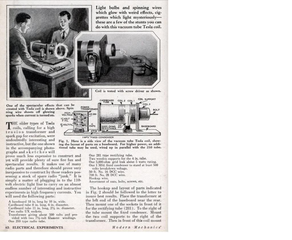
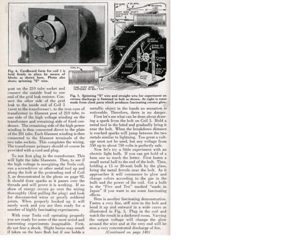
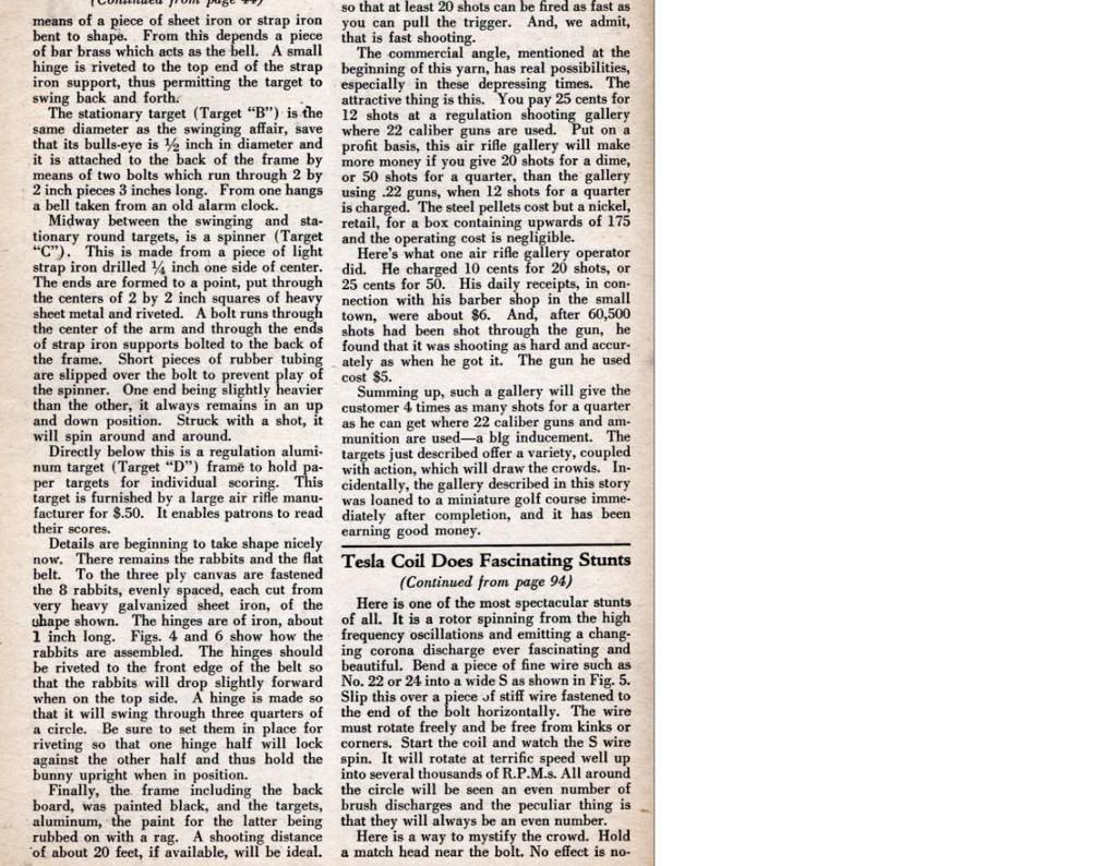
    I found something a few sparkies here may be interested in, its from a magazine "How To Build It" (Jan, 1932) titled Vacuum Tube Tesla Coil Does Fascinating Stunts. It looks like a harmless toy with loads of fun .... I guess well all find out


    Enjoy,
    Glen
    Open Source Experimentalist
    Open Source Research and Development

  • #2
    Hi everyone,

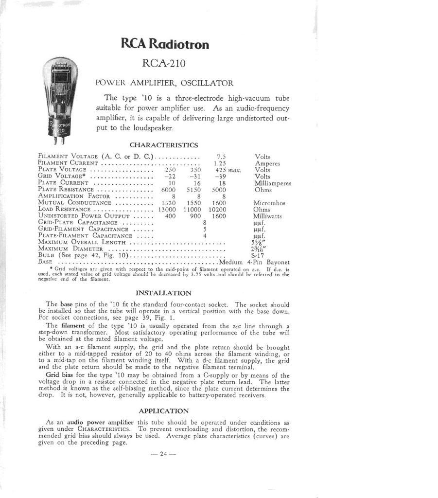
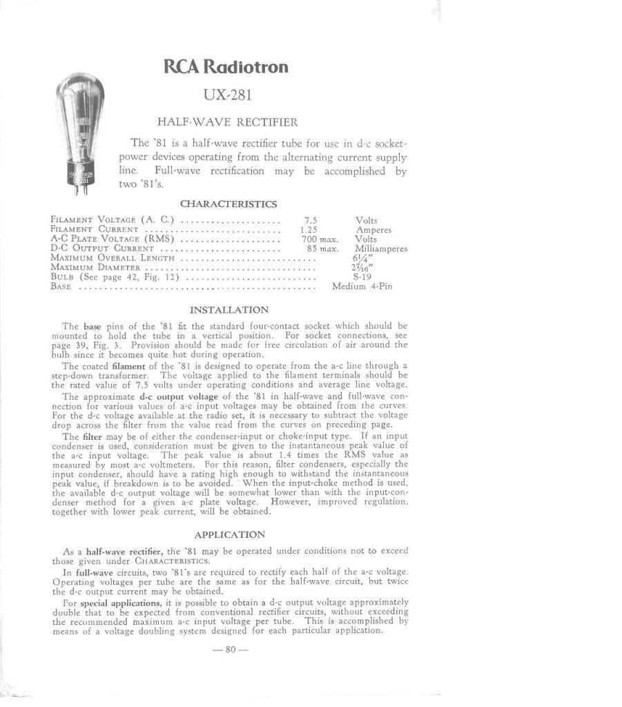
    Here is some information on the "Vacuum Tubes" that are used in this project if needed for any substitutions if required.

    Glen


    Open Source Experimentalist
    Open Source Research and Development

    Comment


    • #3
      I wish someone could explain that circuit to me or draw a normal schematics of it, because I am totally at a loss here.

      They have interconnected the filament connection to the transformer's 500V on the Amp tube, as well as left Grid on the Half-Wave rectifier unconnected.

      How does it even make DC then, not to mention that at this configuration half the wave of 500V is sent to the filament of the Amp tube and then back to the filament pins on the transformer!?
      Are the ravings of a lunatic signs of a genius?

      Comment


      • #4
        Looks like a fun build

        Thanks for posting this. I'll be having some fun with it in my spare time.

        The thing that gets me though is the tube/s. Since I doubt those tubes will be available now what will the equivalent electronics component be? I'm not that sharp to find out these things so I have to ask those in the know.

        Keep up the good works.

        Warren
        ..
        Men had been depending for too long on the authority of the great minds of the past and that they should rely more on their own resources in obtaining knowledge.
        Francis Bacon

        Comment


        • #5
          Originally posted by amigo View Post
          I wish someone could explain that circuit to me or draw a normal schematics of it, because I am totally at a loss here.

          They have interconnected the filament connection to the transformer's 500V on the Amp tube, as well as left Grid on the Half-Wave rectifier unconnected.

          How does it even make DC then, not to mention that at this configuration half the wave of 500V is sent to the filament of the Amp tube and then back to the filament pins on the transformer!?
          Hi amigo,

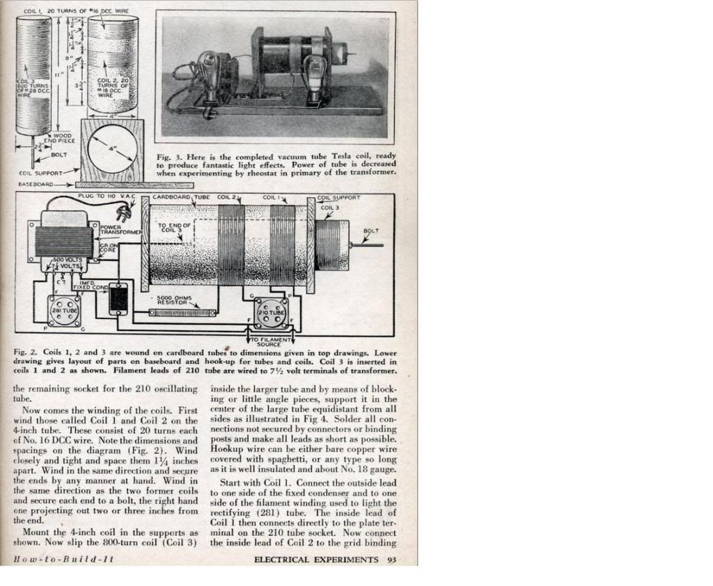
          I understand your confusion at looking over the illustration of Figure 2 it's a strange puppy but after reading the paragraph on page 93 starting with "Start with Coil 1." to the paragraph end on page 94 it tells exactly the same thing thats shown in Figure 2.

          The vacuum tubes are as you know F= filament (2), G = grid, P = plate

          The wiring connection lines in Figure 2 if crossed are connected ie: vacuum tube 210 one (F) Filament, one end 5000 ohm resister, one end condenser, transformer core base (grounded), end of coil 3 and one 500 volt transformer terminal for one group connected or wired together.

          The only wiring not connected is the crossover or the illustrative loops shown on vacuum tube 210 from coil 1 outside wire that goes to the condenser, vacuum tube 281 (F) filament and one side of (1) 7 1/4 volt secondary transformer tap.

          The 210 vacuum tube UX 210, Tube UX210; Röhre UX 210 (UX210)

          The 281 vacuum tube UX 281, Tube UX281; Röhre UX 281 (UX281) does not use (G) grid terminal, there is no internal connection inside.


          The radio power transformer -
          VA ?? (20 - 40)
          110 v primary
          (1)500 v secondary (350v min - 750v max)
          (1)7 1/4 v secondary - for filament (281 tube connections)
          (1)7 1/4 v secondary - for filament (210 tube connections)

          Vacuum Tube cross reference -

          Standard #
          10
          81

          RCA
          210
          281

          Cunningham
          310
          381

          Arcturus
          110
          181

          Deforest
          410
          481

          I'm trying to find out some more information on the old radio transformer to see if theres something special within the secondary windings thats required. If there isn't I'll try to come up with a schematic or maybe someone else here at Energetic can faster, but the connection diagram Figure 2 appears to be a complete one ...... as weird as it looks

          Best Regards,
          Glen
          Last edited by FuzzyTomCat; 04-15-2009, 07:18 AM. Reason: vacuum tube info - in blue
          Open Source Experimentalist
          Open Source Research and Development

          Comment


          • #6
            Originally posted by mrbreau View Post
            Thanks for posting this. I'll be having some fun with it in my spare time.

            The thing that gets me though is the tube/s. Since I doubt those tubes will be available now what will the equivalent electronics component be? I'm not that sharp to find out these things so I have to ask those in the know.

            Keep up the good works.

            Warren
            ..
            Hey mrbreau,

            These radio tubes are available still, I posted cross references to them and looking at the illustration of Figure 2 there could be a reason to use tubes as the 281 vacuum tube isn't connected on the tube "G" or grid, this maybe part of the wireless operation of the device .....

            Good luck on your build ... this should be fun if it works as described in the article.

            Regards,
            Glen
            Open Source Experimentalist
            Open Source Research and Development

            Comment


            • #7
              reply to amigo

              Hey amigo,

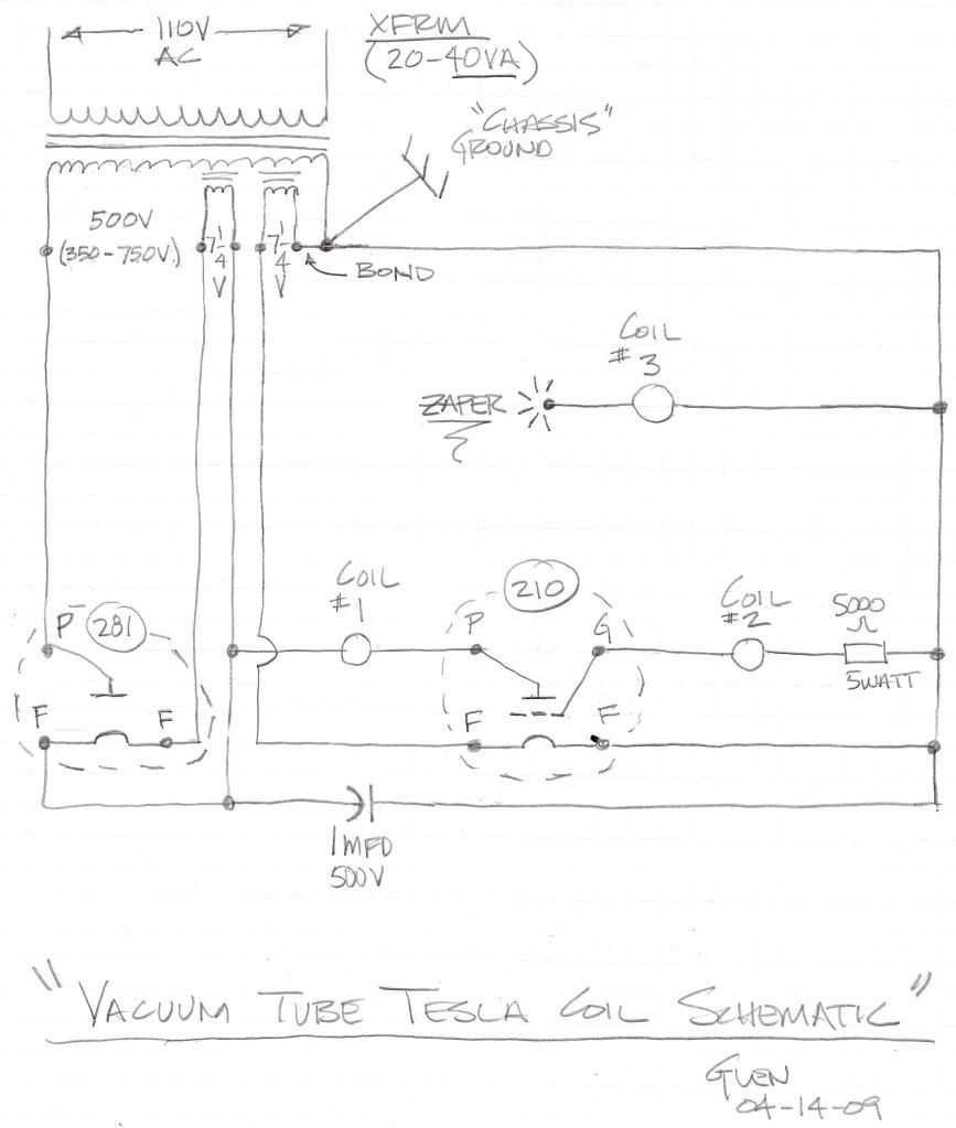
              Had some time and came up with a possible electrical schematic for the illustration Figure 2, I hope this helps you and anyone else that may be interested in doing a build on this "TOY" .....

              There maybe some mistakes but it's the best I can do ....


              Best Regards,
              Glen
              Open Source Experimentalist
              Open Source Research and Development

              Comment


              • #8
                Hey FuzzyTomCat,

                That's a good schematic, thanks.

                So the filaments actually play a role in the overal circuit operation, they are not just there to heat up the tubes. I guess I should've though of it right away , as that was a common thing to do back in those days (before my time obviously).

                How does that Half-Wave tube rectify AC if the gate is not connected anywhere (I thought it's supposed to behave like a diode)? Is it done through the filament ends, but then what happens?

                Since sourcing these transformers is not always easy (I went today to one of the surplus stores that carries all kinds of transformers and could not find a suitable one). Instead I got a 415V and a 600V transformer, but neither have necessary 7.25V for the filament.

                I now wonder if we could modernize this circuit and replace the tubes, or alter the circuit and have separate transformer for the filament, but that would obviously impact the operation, no?
                Are the ravings of a lunatic signs of a genius?

                Comment


                • #9
                  reply to amigo

                  Originally posted by amigo View Post
                  Hey FuzzyTomCat,

                  That's a good schematic, thanks.

                  So the filaments actually play a role in the overal circuit operation, they are not just there to heat up the tubes. I guess I should've though of it right away , as that was a common thing to do back in those days (before my time obviously).

                  How does that Half-Wave tube rectify AC if the gate is not connected anywhere (I thought it's supposed to behave like a diode)? Is it done through the filament ends, but then what happens?

                  Since sourcing these transformers is not always easy (I went today to one of the surplus stores that carries all kinds of transformers and could not find a suitable one). Instead I got a 415V and a 600V transformer, but neither have necessary 7.25V for the filament.

                  I now wonder if we could modernize this circuit and replace the tubes, or alter the circuit and have separate transformer for the filament, but that would obviously impact the operation, no?
                  Hi amigo,

                  As you can see from the circuit something is going on here with the vacuum tubes and how they are connected in the circuit ..... being the date is in 1932 I wonder if this is possibly something Tesla may have made up for grins and giggles, it's just to weird. I have no clue how this puppy works other than the description and figure 2 totally match and electrically looks possible.

                  I think you could use three transformers all with 110 volt primarys as long as the two 7 1/4 volt secondary transformers had one that is bonded to the 350-750 volt transformer winding to the core exteriors for a grounded reference and leave one of the 7 1/4 volt transformer windings "float".

                  And as for updating to a semi conductor model ..... well you got me again, some things just can't be done without being in a vacuum ..... this could be one of them.

                  Best Regards,
                  Glen
                  Last edited by FuzzyTomCat; 04-16-2009, 07:30 AM. Reason: spelling - grammer
                  Open Source Experimentalist
                  Open Source Research and Development

                  Comment


                  • #10
                    Originally posted by FuzzyTomCat View Post
                    As you can see from the circuit something is going on here with the vacuum tubes and how they are connected in the circuit ..... being the date is in 1932 I wonder if this is possibly something Tesla may have made up for grins and giggles, it's just to weird. I have no clue how this puppy works other than the description and figure 2 totally match and electrically looks possible.
                    This circuit/article was not done by Tesla, was it?

                    I thought it was just someone's utilization of Tesla's coil in production of HV?
                    Are the ravings of a lunatic signs of a genius?

                    Comment


                    • #11
                      reply to amigo

                      Originally posted by amigo View Post
                      This circuit/article was not done by Tesla, was it?

                      I thought it was just someone's utilization of Tesla's coil in production of HV?
                      Hi amigo,

                      You make a very good point about Tesla as there is no proof not even any information on where or who this device came from other than "Modern Mechanics & Inventions" 1932. I have been trying to find out more information and what there is the publications of Home Mechanix, Modern Mechanics & Inventions, Modern Mechanix, Mechanix Illustrated and Todays Homeowners in this order started in 1928 and went until 2001 from one magazine name to another name from the same publisher. In mostly all the articles from 1928 until 1937 the magazines had little information on where or who the article came from not even the inventors names were included. It is also known that after Tesla announced he was in continued communication with Mars for years some publications and articles didn't have his name on them or the publishers just stayed away.

                      It is only my guessing because at the time of this article was written he would be 76 years old and his knowledge in the Tesla Coil, Vacuum Tubes and the way the spark gap had been changed and replaced by a rectifier and a amplifier oscillator vacuum tube to make this curiosity of a "toy". How may other individuals back then could come up with this with there knowledge or has anyone seen this configuration before, its posted here and at OverUnity also, no one has said "Oh ya we've know about this for years" or here's a solid state version ......... nothing, maybe it's a Tesla practical operational device joke?

                      Then there are articles one year before of a 1931 Pierce Arrow car being run by wireless power and vacuum tubes ...... connection maybe? At this time without more information on the publisher or writer and where this device actually came from or who did it, it's "only" a guess on my behalf.

                      Best Regards,
                      Glen
                      Open Source Experimentalist
                      Open Source Research and Development

                      Comment


                      • #12
                        Hi FuzzyTomCat,

                        You are right, we don't have enough information. For all we know it could've really been Tesla writing an article for the magazine, for a fee, or for the kicks as you suggest.

                        Either way, it might be worth while building so I'll give it a shot, eventually, after I source all the parts or replace them with modern components.
                        Are the ravings of a lunatic signs of a genius?

                        Comment


                        • #13
                          Originally posted by amigo View Post
                          Hi FuzzyTomCat,

                          You are right, we don't have enough information. For all we know it could've really been Tesla writing an article for the magazine, for a fee, or for the kicks as you suggest.

                          Either way, it might be worth while building so I'll give it a shot, eventually, after I source all the parts or replace them with modern components.
                          Hi amigo,

                          I'm working on building one also , it will be one using three transformers and PVC tubing instead of the cardboard if the right sizes are available or close to keep any ratios the same. I wonder why this (toy) is a 6 HZ device as stated on the last page of the article, or what would happen if the frequency was changed higher ..... I read a 1904 article from J Ambrose Flemming who invented the "Diode Vacuum Tube" and showed how one could detect radio signals. At 6 HZ there wasn't anything that low maybe something for submarines, radio was at 9 to 23 KHZ and the way it is connected in the schematic?? I don't know why they stayed away from known frequency's there is some reason though ...... maybe you or someone else on the forum would know or like to comment at some time.

                          Best Regards,
                          Glen
                          Open Source Experimentalist
                          Open Source Research and Development

                          Comment


                          • #14
                            Hi FuzzyTomCat,

                            Are you building per the original schematic using the RCA tubes, or replacement ones; or a solid state version?

                            I will admit I haven't read the entire article yet, but the thing about 6 Hz frequency, as far as I could read around the Web there is a lot of speculation that Tesla was trying to/tapping into that range either because of the Schumann Resonance or some other outer Cosmic reason.

                            I'm just not sure how would it all work when the necessary antennas for such a low frequency would be thousands of kilometers long. I guess a harmonic of that frequency, but then why mention the 6 Hz altogether.

                            EDIT: I was just looking at availability of UX 210 and they seem to be sort of expensive and hard to get items. The equivalent to it is CX-310 and one site I saw wanted almost $400 for NOS.
                            Last edited by amigo; 04-18-2009, 09:09 PM.
                            Are the ravings of a lunatic signs of a genius?

                            Comment


                            • #15
                              Hi amigo,

                              Yep, I want to build the original design or as close as I can, so as to see the device operation as published. I sure hope the number 10 and 81 series vacuum tubes are less expensive than what you have found already but I'll have to look around and see, I'll post anything good I find.

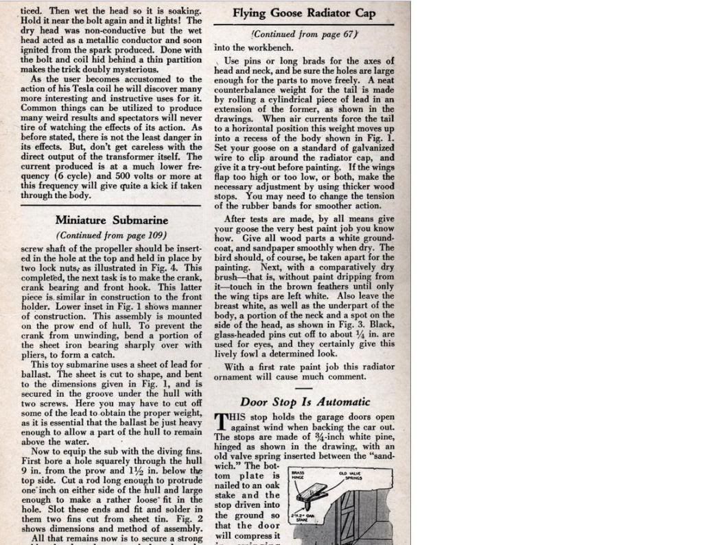
                              The 6 cycle thing is strange, earlier in the article it states [quote] First, do not fear a shock. Slight burns may result if taken on the bare flesh but if one holds a metallic object in the hands no sensation is noticeable. Therefore there is no danger. [end quote] Then the article end is the, OH ... YA [quote] As before stated, there is not the least danger in its effects. But, don't get careless with the direct output of the transformer itself. The current produced is at a much lower frequency (6 cycles) and 500 volts or more at this frequency it will give quite the kick if taken through the body. [end quote] ...... sounds like something I want to give to all my kids

                              Best,
                              Glen
                              Last edited by FuzzyTomCat; 04-19-2009, 03:45 AM. Reason: grammer spelling
                              Open Source Experimentalist
                              Open Source Research and Development

                              Comment

                              Working...
                              X