 Tweet
Tweet
Vacuum Tube Information
Hi everyone,
Here is one source for the required vacuum tubes for the "Vacuum Tube Tesla Coil" if you haven't already found one, there usually in old or antique radio parts stores.
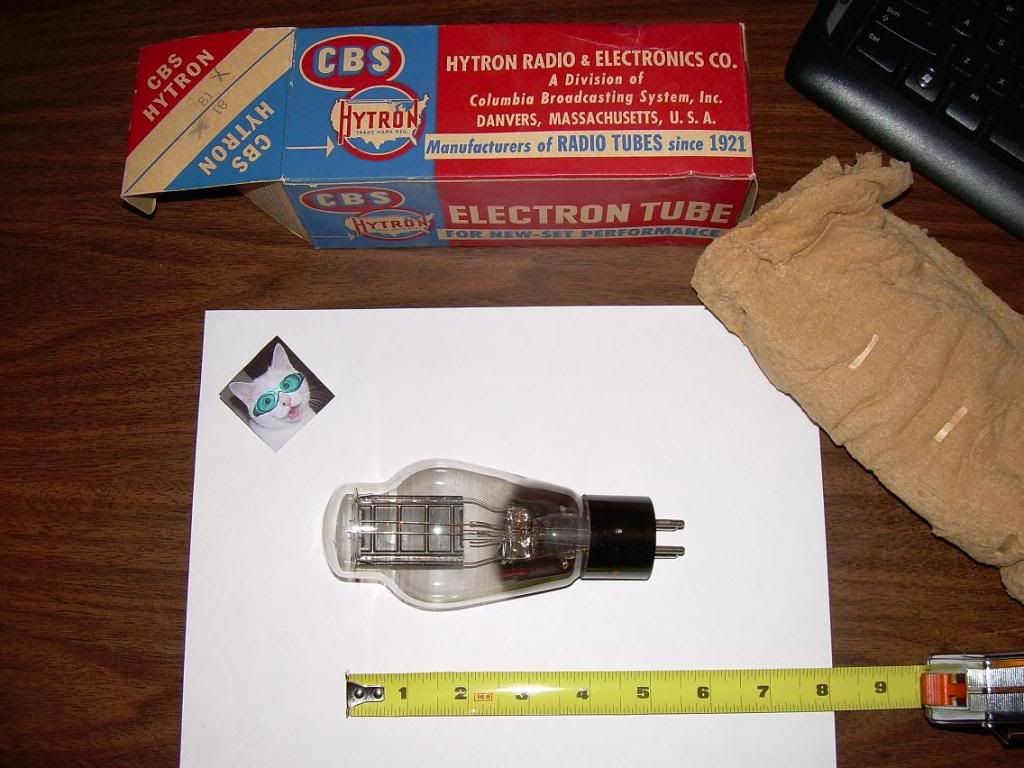
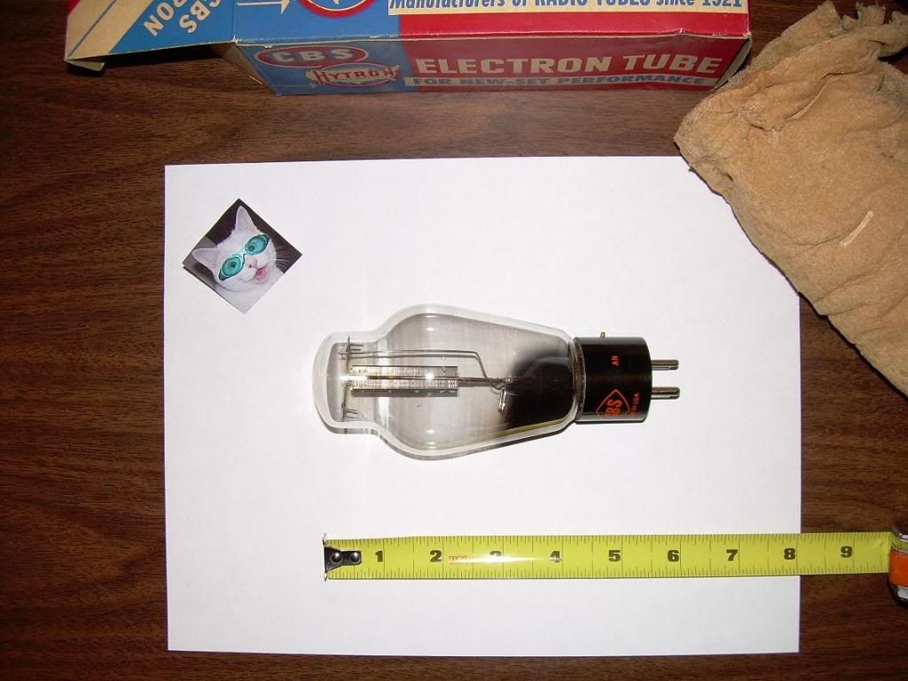
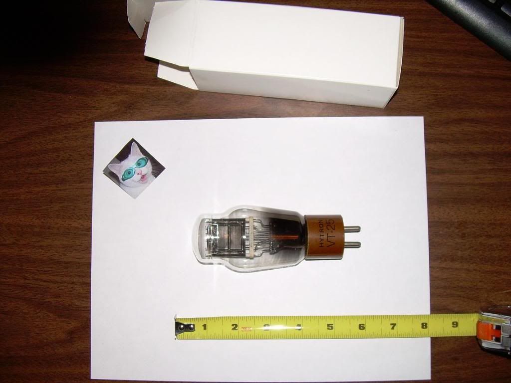
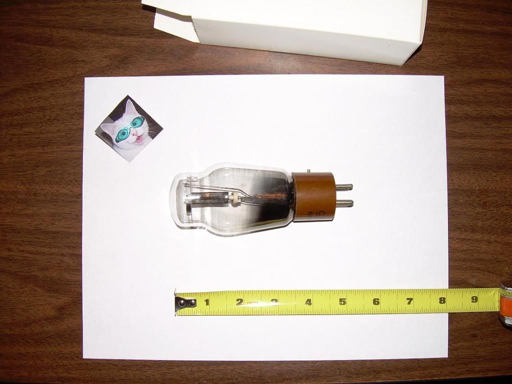
10 Triode ST Shape ($69.95 US) ST type
81 (ST) ($15.95 US) ST type
10 Triode Globe Shape ($99.95 US)
81 Rectifier Globe Shape ($89.95 US)
The difference in the two referenced is the exterior globe style ...
Glen

Hi everyone,
Here is one source for the required vacuum tubes for the "Vacuum Tube Tesla Coil" if you haven't already found one, there usually in old or antique radio parts stores.
10 Triode ST Shape ($69.95 US) ST type
81 (ST) ($15.95 US) ST type
10 Triode Globe Shape ($99.95 US)
81 Rectifier Globe Shape ($89.95 US)
The difference in the two referenced is the exterior globe style ...
Glen

 I think eveyone should enjoy just a little electrotheropy once in awhile ....
  maybe see some electrons !!


")

Comment